Table of Contents
Advertisement
Quick Links
Installation, Operation and
Maintenance Manual
254 Nanometer Germicidal
UV Disinfection Systems
Models
PWC012 PWC016 PWC020 PWC025 PWC040 PWC050
PWD012 PWD016 PWD020 PWD025 PWD040 PWD050
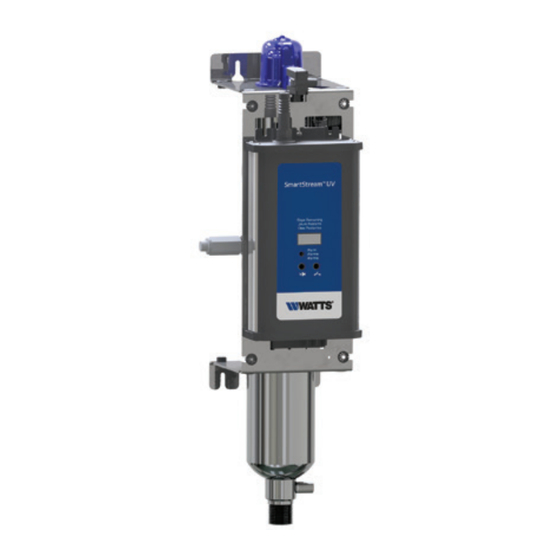
SmartStream
™
Chemical Free Disinfection of Water
WARNING
!
Read this Manual BEFORE using this
equipment. Failure to read and follow
all safety and user information can
result in death, serious personal injury,
property damage, or damage to the equipment.
Keep this Manual for future reference.
This device complies with part 15 of the FCC Rules. Operation
is subject to the following two conditions: (1) This device may
not cause harmful interference, and (2) this device must accept
any interference received, including interference that may cause
undesired operation.
This device complies with Industry Canada licence-exempt RSS
standard(s). Operation is subject to the following two condi-
tions: (1) this device may not cause interference, and (2) this
device must accept any interference, including interference that
may cause undesired operation of the device.
Lé present appareil est conforme aux CNR d'Industrie
Canada applicables aux appareils radio exempts de licence.
L'exploitation est autorisée aux deux conditions suivantes : (1)
l'appareil ne doit pas produire de brouillage, et (2) l'utilisateur
de l'appareil doit accepter tout brouillage radioélectrique subi,
même si le brouillage est susceptible d'en compromettre le
fonctionnement.
Any changes or modifications of this product not approved by
the manufacturer could void the user's authority to operate the
equipment.
This equipment complies with IC RSS-102 radiation exposure
limits set forth for an uncontrolled environment. This equipment
should be installed and operated with minimum distance 20cm
between the radiator & your body.
Under Industry Canada regulations, this radio transmitter may
only operate using an antenna of a type and maximum (or
lesser) gain approved for the transmitter by Industry Canada. To
reduce potential radio interference to other users, the antenna
type and its gain should be so chosen that the equivalent iso-
tropically radiated power (e.i.r.p.) is not more than that neces-
sary for successful communication.
UV
SmartStream UV is certified by the Water Quality
™
Association (WQA) to NSF/ANSI Standard 372
for lead free.
WARNING
!
This system contains a UV-C emitter (UV lamp)
• DO NOT look directly at the UV lamp while it
is ON. Permanent serious eye damage could
occur.
• DO NOT use if UV lamp, housing or any part of
system is damaged.
• Any damage to UV lamp or misuse of system
UV
could result in escape of dangerous UV-C radia-
tion. UV-C radiation even in small doses can
cause harm to eyes and skin.
• NEVER use UV lamp if it is removed from the
housing (enclosure).
• ALWAYS turn OFF and disconnect (unplug) sys-
tem from power supply BEFORE replacing UV
lamp or performing any repairs or maintenance.
Table of Contents
Installation Precautions . . . . . . . . . . . . . . . . . . . . . . . . . . . . . . . . . . . 3
System Specifications . . . . . . . . . . . . . . . . . . . . . . . . . . . . . . . . . . 4-7
Product Specification Tables . . . . . . . . . . . . . . . . . . . . . . . . . . . . . 5-7
Dimensions . . . . . . . . . . . . . . . . . . . . . . . . . . . . . . . . . . . . . . . . . . . . 8
Feed Water Requirements . . . . . . . . . . . . . . . . . . . . . . . . . . . . . . . . . 9
Installation Procedure . . . . . . . . . . . . . . . . . . . . . . . . . . . . . . . . . 9-10
Maintenance . . . . . . . . . . . . . . . . . . . . . . . . . . . . . . . . . . . . . . . . . . 11
Lamp and Quartz Sleeve Replacement . . . . . . . . . . . . . . . . . . . . . . 11
Disinfection Procedure. . . . . . . . . . . . . . . . . . . . . . . . . . . . . . . . . . . 11
Parts List . . . . . . . . . . . . . . . . . . . . . . . . . . . . . . . . . . . . . . . . . . 12-13
Troubleshooting . . . . . . . . . . . . . . . . . . . . . . . . . . . . . . . . . . . . . . . . 14
Controller Identification . . . . . . . . . . . . . . . . . . . . . . . . . . . . . . . . . . 15
Overview of Screens . . . . . . . . . . . . . . . . . . . . . . . . . . . . . . . . . 16-20
Controller Wiring . . . . . . . . . . . . . . . . . . . . . . . . . . . . . . . . . . . . . . . 21
Warranty and Conditions . . . . . . . . . . . . . . . . . . . . . . . . . . . . . . . . . 24
IOM-PW-SmartStream-C_D
Original Instructions
Advertisement
Table of Contents

Related Manuals for Watts SmartStream UV PWC012


Summary of Contents for Watts SmartStream UV PWC012
-
Page 1: Table Of Contents
IOM-PW-SmartStream-C_D Installation, Operation and Original Instructions Maintenance Manual 254 Nanometer Germicidal UV Disinfection Systems Models PWC012 PWC016 PWC020 PWC025 PWC040 PWC050 PWD012 PWD016 PWD020 PWD025 PWD040 PWD050 SmartStream ™ Chemical Free Disinfection of Water WARNING SmartStream UV is certified by the Water Quality ™... - Page 2 Introduction safety symbols, signals, and pictorials. Thank you for purchasing the Watts SmartStream™ line of ultra- violet disinfection systems. SmartStream™ provides protection This is a safety-alert symbol. The against microbiological contamination in water for residential and safety alert symbol is shown alone or commercial applications.
- Page 3 UV transmittance into the water. WARNING Use only Watts supplied UV lamps and quartz sleeves for your specific model. Failure to do so may result in system failure and DO NOT touch the quartz sleeve with your fingers. Hold it with will void all warranty.
-
Page 4: System Specifications
SmartStream UV System Part Number Identification Key ™ Prefix "W" "Controller Series" "GPM" "Connection Type" "Pipe Size" "Plug" "Accessories" Watts Controller Type GPM of System Connection Port Pipe Size A: North American Accessories C: Controller C (3-Digits) Types: B: 3/8"... -
Page 5: Product Specification Tables
INPUT VOLTAGE 100 to 240VAC 50/60Hz SYSTEM MAX NOMINAL INPUT POWER (Watts) LAMP MAX NOMINAL ELECTRICAL POWER (Watts) LAMP TECHNOLOGY Quartz glass low pressure lamp / ozone free / true pre-heat starting / glow-cap indicator WIRELESS LAMP KEY Standard LAMP DIMMING / FLOW SWITCH... - Page 6 INPUT VOLTAGE 100 to 240VAC 50/60Hz SYSTEM MAX NOMINAL INPUT POWER (Watts) LAMP MAX NOMINAL ELECTRICAL POWER (Watts) LAMP TECHNOLOGY Quartz glass low pressure lamp / ozone free / true pre-heat starting / glow-cap indicator WIRELESS LAMP KEY Standard LAMP DIMMING / FLOW SWITCH...
-
Page 7: Dimensions
Dimensions Controller Mounted on Chamber- 12 to 50 GPM All dimensions are in inches. 3.34 23.92 24.95 7.63 8.29 3.00 4.50 16.00 22.00 3.34 27.86 28.89 7.63 8.29 3.00 4.50 16.00 26.00 3.34 31.40 32.43 7.63 8.29 3.00 4.50 16.00 30.00 3.34 31.64 32.67 8.13... -
Page 8: Feed Water Requirements
18**. If using the solenoid valve safety shut off feature, connect the solenoid valve's power wires to the solenoid valve power output on UV system controller. Then plug the sole- noid valve transformer into a power outlet. Use only Watts... - Page 9 supplied solenoid valve kit part number T7401001 for 20 GPM systems and below and part T7401002 for 25 GPM systems and above. 19. Open water supply valves. 20. Check for leaks and repair as needed. 21. Plug in power cord. 22.
-
Page 10: Maintenance
NOTICE Maintenance UV Lamps have a 1 year (9000 Hour) life span under normal it is discolored, is must be replaced. operating conditions. Pre filters should be maintained according to the manufactur- Quartz sleeves should be cleaned with vinegar, citric acid, or a ers instructions to ensure feed water requirements within this lime scale removing chemical annually and replaced no less than manual are met. -
Page 11: Disinfection Procedure
Disinfection Procedure 3. Install a new prefilter cartridge and pour 1 cup of 6% bleach NOTICE into the housing. If an activated carbon cartridge is part of the prefiltration system it must be removed during the disin- If hot water is used during disinfection procedure, please use fection procedure. -
Page 12: Parts List
Parts List ITEM QTY. ORDERING CODE DESCRIPTION T7402039 Bracket for Mounting 12-20 GPM UV Chamber T7402038 Bracket for Mounting 25-50 GPM UV Chamber T7400153 UV Chamber 3.5" OD 12 GPM 1" MNPT X 3/4" FNPT Combo for C & D Series Controller T7400154 UV Chamber 3.5"... -
Page 13: Troubleshooting
Troubleshooting PROBLEM POSSIBLE CAUSE CORRECTIVE ACTION Bacteria in outlet water Low or no UV transmittance into the water Replace lamp Clean or replace quartz sleeve Replace prefilter Confirm the pretreatment is adequate Confirm the feed water meets the feed water require- ments within this manual Biofilm in outlet plumbing System needs to be sterilized... - Page 14 C Series Controller Screen and LED Identifi cation C Controller- Displays lamp life days remaining, Display dim- ming light indicator, Button for silencing the alarm, Button for overriding the alarm relay, LED Status Indicator Lamp Cable LED Display- Days remaining and lamp dimming System Status Indicator LED: Green- operation normal...
-
Page 15: Overview Of Screens
D Series Controller- Overview of Screens Startup Screen- Lamp Warm Up Screen- Home Screen- When the system is first Once Startup Screen system Upon completion of the Lamp Warm Up Screen powered up, this screen will checks are complete, the lamp the Home Screen will automatically appear. - Page 16 Start Up Screen Normal Operation System checks are automatically executed by the controller in the Start Up Screen then the system advances to the Lamp Warm Up Screen. If an abnormal condition exists, a variety of alarms can be displayed. Possible Alarms Upon start-up of the system, if the UV sensor is not found, the user will be notified via this screen.
- Page 17 Home Screen The Home Screen is the normal operating screen for the system. In this graphic the lamp is operating at full power. If an alarm or warning condition occurs, the system will notify the user from this screen. This graphic shows the lamp to be in a dimmed condition to reduce water temperature and con- serve energy.
- Page 18 Set Up Screen The Set Up Screen can be accessed by pressing the gear icon on the Home Screen. This allows the user to select a language, bypass the alarm relay, and silence audible alarms. Touching the house icon returns the user to the Home Screen. Bypassing Alarms-Alarm Relay Output Bypassing Alarms-Audible Alarms Touching the alarm over-...
- Page 19 Lamp and Sleeve Replacement Screen The Lamp and Sleeve Replacement Screen can be accessed by touching the information icon at the bottom of the Home Screen. This will provide the system model number along with the model number and QR codes for replacement lamps and quartz sleeves.
-
Page 20: Controller Wiring
Series C and D Controller Wiring Top Cat 5- Future Accessories Bottom Cat 5- UV Sensor Alarm Relay A (Left to Right) Normally Closed/Common/ Normally Open Alarm Relay B (Left to Right) Normally Closed/Common/ Normally Open Power Input AC 100-240 VAC 50/60HZ Right- Ground to Chassis Center- Flow Switch... - Page 21 Notes...
- Page 22 Notes...
- Page 23 Notes...
- Page 24 State of California to cause cancer and birth defects or other reproductive harm. For more information: www.watts.com/prop65 USA: T: (800) 224-1299 • F: (978) 794-1848 • Watts.com/PureWater Canada: T: (905) 332-4090 • F: (905) 332-7068 • Watts.ca/PureWater Latin America: T: (52) 81-1001-8600 • Watts.com/PureWater...
Need help?
Do you have a question about the SmartStream UV PWC012 and is the answer not in the manual?
Questions and answers