Advertisement
Quick Links
MAX
illuminators installation guide
(including IR Covert, IR PLATINUM, HYBRID and Low Voltage Series)
This installation guide provides instructions for installing the RAYMAX
and RAYLUX series illuminators
Installation Steps
1. Mount Illuminator
2. Mount Power Supply Unit (PSU)
3. Connect Illuminator to PSU
4. PSU connections
5. Connect PSU to Mains
Set Up Steps
1. Position illuminator adjacent to
camera and point towards scene
2. Adjust vertical angle
3. Adjust horizontal angle via Adaptive
Illumination (AI) (if required)
4. Tighten all fixings
Package Contents
1. Illuminator
2. Power Supply (PSU)
GOLDEN RULES:
1. Ensure PSU lid orientation has
warning label in line with glands
(see PSU diagram, right)
2. Ensure operating voltage is
correct for unit being installed
3. DO NOT INPUT MAINS VOLTAGE
INTO LOW VOLTAGE PSU
4. Ensure PSU is fully water tight
and
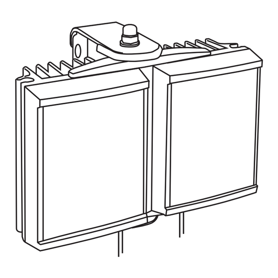
RAYMAX / RAYLUX illuminator
LUX
Overview
PSU
1
Advertisement


Need help?
Do you have a question about the Raymax Series and is the answer not in the manual?
Questions and answers