
Related Manuals for Areca ARC-8042-12


Summary of Contents for Areca ARC-8042-12
- Page 1 RAID Subsystem ARC-8042-12 SAS Desktop RAID Subsystem User’s Manual Version: 1.1 Issue Date: July, 2018...
- Page 2 Manufacturer’s Declaration for CE Certification We confirm ARC-8042-12 12-bays 12Gb/s SAS RAID subsystem has been tested and found compliant with the requirements in the council directive relating to the EMC Directive 2004/108/EC. Regarding to the...
-
Page 3: Table Of Contents
Contents 1. Introduction .............. 12 1.1 Overview ................ 12 1.2 Technical Specifications ............. 14 1.3 RAID subsystem View ............17 1.4 Locations of the Subsystem Component ......18 1.4.1 Drive Tray LED Indicators ..........18 1.4.2 LCD Panel LED Indicators ..........19 1.5 RAID Subsystem Alarm ............. - Page 4 4.7 Navigation Map of the LCD ..........43 4.7.1 Quick Volume And Raid Setup ........44 4.7.2 Raid Set Functions ............44 4.7.2.1 Create A New Raid Set ........... 45 4.7.2.2 Delete Raid Set ............45 4.7.2.3 Expand Raid Set ............. 46 4.7.2.4 Offline Raid Set ............
- Page 5 4.7.5.10 Disk Capacity Truncation Mode........ 60 4.7.5.11 Shutdown The Controller ........60 4.7.5.12 Restart Controller ..........61 4.7.6 Hdd Power Management ..........61 4.7.6.1 Stagger Power On Control ........61 4.7.6.2 Time To Hdd Low Power Idle ........62 4.7.6.3 Time To Hdd Low RPM Mode ........62 4.7.6.4 Time To Spin Down Idle HDD ........
- Page 6 5.5.3.1.4 Stripe Size ............87 5.5.3.1.5 SAS Port # ............87 5.5.3.1.6 LUN Base ............88 5.5.3.1.7 SAS LUN ............88 5.5.3.1.8 Cache Mode ............89 5.5.3.1.9 Tag Queuing ............89 5.5.3.2 Create Raid30/50/60 ..........90 5.5.3.3 Delete Volume Set ..........91 5.5.3.4 Modify Volume Set ..........
- Page 7 5.5.7 HDD Power Management ..........111 5.5.7.1 Stagger Power On ..........112 5.5.7.2 Time to Hdd Low Power Idle (Minutes) ..... 113 5.5.7.3 Time To Low RPM Mode (Minutes) ......113 5.5.7.4 Time To Spin Down Idle Hdd (Minutes) ....114 5.5.8 In Band SAS Config ...........
- Page 8 6.6.3 Delete Volume Set ............. 139 6.6.4 Modify Volume Set ............. 140 6.6.4.1 Volume Growth ............ 141 6.6.4.2 Volume Set Migration ..........141 6.6.5 Check Volume Set ............. 142 6.6.6 Schedule Volume Check ..........143 6.6.7 Stop Volume Check ............ 144 6.7 Security Function ............
- Page 9 6.9.2 Advanced Configuration ..........160 6.9.3 Hdd Power Management ..........166 6.9.3.1 Stagger Power On Control ........166 6.9.3.2 Time To Hdd Low Power Idle ........167 6.9.3.3 Time To Hdd Low RPM Mode ........167 6.9.3.4 Time To Spin Down Idle HDD ........ 167 6.9.3.5 Time To Wait HDD Spin Up ........
- Page 10 A. Device Event ............... 190 B. Volume Event .............. 191 C. RAID Set Event ............192 D. Hardware Monitor Event ..........192 Appendix E ..............194 Self-Encrypting Disk (SED) Encryption ........194 Appendix F ..............200 RAID Concept ..............200 RAID Set ................
-
Page 12: Introduction
INTRODUCTION 1. Introduction This section presents a brief overview of the ARC-8042-12 12bays 12Gb/s SAS to SAS desktop RAID subsystem. 1.1 Overview The ARC-8042-12 SAS to SAS desktop RAID subsystem provides 12Gb/s SAS host interface link to the host board on the server system. - Page 13 NAS, supercomputing, near-line backup, security systems, streaming and cloud computing applications. Unsurpassed Data Availability Designed and leveraged with Areca’s existing high performance RAID solution, ARC-8042-12 provides superior levels performance and enterprise level data protection for the most demanding next generation server and storage environments.
-
Page 14: Technical Specifications
INTRODUCTION 1.2 Technical Specifications Controller Architecture • Dual Core RAID-on-Chip (ROC) 1.2 GHz • On-board 2GB DDR3-1866 ECC SDRAM • NVRAM for RAID event log & transaction log • Write-through or write-back cache support • Redundant flash image for adapter availability •... - Page 15 INTRODUCTION • SNMP support for remote manager • Enclosure management ready (SES over in-band SAS) Drive Interface • Up to 512 devices using SAS expanders (two external SFF-8644 connectors: EXP.0 & EXP.1) • Up to 12 x 12Gb/s internal ports Host Interface 12Gb/s SAS-to-SAS •...
- Page 16 INTRODUCTION LED Indicators Hard-drive carrier • 1 blue single-color activity LED status indicator • 1 dual-color fault/power LED status indicator Controller board • 2 x single-color LED status indicators for subsystem, one for power-on and one for subsystem fault status •...
-
Page 17: Raid Subsystem View
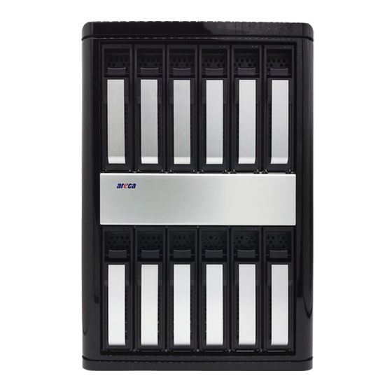
INTRODUCTION 1.3 RAID subsystem View The following diagram is the ARC-8042-12 desktop RAID subsys- tem front view and rear view. Front View Rear View 1. Disk Activity LED 4. SAS Host Port0 (CH0) 2. Disk Fault/Link LED 5. SAS Host Port1 (CH1) 3. -
Page 18: Locations Of The Subsystem Component
INTRODUCTION 1.4 Locations of the Subsystem Component The following components come with LEDs that inform ARC-8042-12 RAID storage managers about the operational status. 1.4.1 Drive Tray LED Indicators Figure 1-1, Activity/Fault LED The following table describes the RAID storage disk drive tray LED behavior. -
Page 19: Lcd Panel Led Indicators
INTRODUCTION 1.4.2 LCD Panel LED Indicators There are a variety of status conditions that cause the RAID stor- age panel monitoring LED to light. The front panel LCD comes with three (3) status-indicating LEDs. The LEDs on the front panel are defined, from top to bottom, Power, Busy, and Caution, as shown in Figure 1-2. -
Page 20: Expansion Connection
INTRODUCTION 1.6 Expansion Connection SAS RAID subsystem is a device that contains one expander port. Expander port may support being attached to SAS initiator ports, SAS and/or SATA target ports, and to other expander ports. The SAS RAID subsystem can connect up to 7 expander enclosures to the host system. -
Page 21: Hardware Installation
HARDWARE INSTALLATION 2. Hardware Installation Thanks for purchasing the ARC-8042-12 as your SAS RAID subsys- tem. The following manual gives simple step-by-step instructions for installing and configuring the ARC-8042-12 SAS RAID subsys- tem. Unpack Unpack and install the hardware in a static-free environment. The SAS RAID subsystem is packed inside an anti-static bag between two sponge sheets. -
Page 22: Installing Or Removing Drives In The Subsystem
HARDWARE INSTALLATION 2.1 Installing or Removing Drives in the Subsystem Your subsystem supports up to 12 3.5-inch disk drives or 2.5-inch 12Gb/s SAS or 6Gb/s SAS/SATA drives, each one contained in its individual drive carrier. Each drive is hot-pluggable, allowing you to remove and insert drives without shutting down your subsystem. -
Page 23: Removing Drives From The Subsystem
HARDWARE INSTALLATION 2. After installing the drive into the drive tray completely, make sure the drive tray latch is open, then slide the drive tray with the attached drive into the subsystem and make sure you latch the drive trays. Figure 2-3, Sliding Drive Tray into Enclosure 2.1.2 Removing Drives from the Subsystem 1. -
Page 24: Connecting The Raid Subsystem
The external host connector is provided on the back of the SAS RAID subsystem for connecting the array to server host adapter. The ARC-8042-12 RAID controller has two (2) SFF-8644 SAS IN Port connectors and two (2) SFF-8644 SAS Expansion Port connector. -
Page 25: Connecting Monitor Port
LAN port. • Terminal Port Connection Figure 2-6, Terminal Monitor Port Location The ARC-8042-12 SAS RAID subsystem can be configured via a VT-100 compatible terminal or a PC running a VT-100 terminal emulation program. You can attach a serial (Character-Based) terminal or server com port to the SAS JBOD enclosure for access to the text-based setup menu. - Page 26 HARDWARE INSTALLATION SW1-2 SW1-1 Terminal Port Function Expander Terminal Expander Debug Controller Terminal Controller Debug Table 2-1, Terminal Port Function Definition The SAS RAID subsystem package includes one RJ11-to-DB9 serial data cable. Use the RJ11 serial port on the controller module to establish the serial communication link.
-
Page 27: Power Up The Raid Subsystem
Turning off subsystem power with this switch removes the main power but keeps standby power supplied to the RAID subsystem. Therefore, you must unplug the power cord before subsystem servicing. The installation is completed. You can use your ARC-8042-12 SAS RAID subsystem. -
Page 28: Configuring Raid Subsystems
HARDWARE INSTALLATION 2.3 Configuring RAID Subsystems There are often multiple ways to accomplish the same configuration and maintenance tasks for your SAS RAID subsystem. The SAS RAID subsystem is normally delivered with LCD preinstalled. Your SAS RAID subsystem can be configured by using the LCD with keypad, a serial device (terminal emulation) or LAN port. -
Page 29: Format, Partition And Mount The Sas Raid Subsystem Volumes
HARDWARE INSTALLATION • Method 3: LAN Port Connection For additional information on using the LAN port to configure the RAID subsystem see the Chapter 6 of Web Browser-Based Configuration. Note: It's a good ideal to turn on your SAS RAID subsystem before turning on the host computer. -
Page 30: Configuration Methods
CONFIGURATION METHOD 3. Configuration Methods After the hardware installation, the SAS/SATA disk drives connected to the SAS RAID subsystem must be configured and the volume set units initialized before they are ready to use. This can be accomplished by one of the following methods: •... - Page 31 CONFIGURATION METHOD The LCD provides a system of screens with areas for information, status indication, or menus. The LCD screen displays up to two lines at a time of menu items or other information. The initial screen is as the following: Function Key Definitions: The four function keys at the button of the front perform the fol- lowing functions:...
-
Page 32: Vt100 Terminal (Using The Controller's Serial Port)
CONFIGURATION METHOD 3.2 VT100 terminal (Using the controller’s serial port) The serial port on the SAS RAID subsystem’s front can be used in VT100 mode. The provided interface cable converts the RS232 signal of the 6-pin RJ11 connector on the RAID subsystem into a 9-pin D-Sub female connector. -
Page 33: Start-Up Vt100 Screen
CONFIGURATION METHOD Keyboard Navigation The following definition is the VT-100 RAID configuration utility keyboard navigation. Function Arrow Key Move cursor Enter Key Submit selection function ESC Key Return to previous screen L Key Line draw X Key Redraw 3.2.2 Start-up VT100 Screen By connecting a VT100 compatible terminal, or a PC operating in an equivalent terminal emulation mode, all SAS RAID subsystem monitoring, configuration and administration functions can be... - Page 34 CONFIGURATION METHOD Step 3. Select an appropriate connecting port in your Terminal. Click OK. Configure the port parameter settings. Bits per second: “115200”, Data bits: “8”, Parity: ”None”, Stop bits: “1”, Flow control:” None”. Click “OK”. Step 4. Open the File menu, and then open Properties. Step 5.
- Page 35 CONFIGURATION METHOD Step 6. Open the Settings Tab. Function, arrow and ctrl keys act as: Terminal Keys, Backspace key sends: “Crtl+H”, Emulation: VT100, Telnet terminal: VT100, Back scroll buffer lines: 500. Click OK. Now, the VT100 is ready to use. After you have finished the VT100 Terminal setup, you may press “...
-
Page 36: Web Browser-Based Raid Manager
CONFIGURATION METHOD 3.3 Web browser-based RAID manager To configure SAS RAID subsystem on a local or remote machine, you need to know its IP Address. The IP address will default be shown in the "LCD" screen, or get from VT-100 System Information or ArcSAP utility. - Page 37 CONFIGURATION METHOD Note: Ethernet Configuration, Alert By Mail Config, and SNMP Config can only be set in the web-based configuration.
-
Page 38: Lcd Configuration Menu
LCD CONFIGURATION MENU 4. LCD Configuration Menu After the hardware installation, the disk drives connected to the RAID subsystem must be configured and the volume set units initialized before they are ready to use. This can be also accomplished by the front panel touch-control keypad. -
Page 39: Lcd Configuration Utility Main Menu Options
LCD CONFIGURATION MENU 4.2 LCD Configuration Utility Main Menu Options Select an option, related information or submenu items to display beneath it. The submenus for each item are explained on the sec- tion 4.7.2. The configuration utility main menu options are: Option Description Quick Volume And Raid Set... -
Page 40: Designating Drives As Hot Spares
LCD CONFIGURATION MENU 4.4 Designating Drives as Hot Spares To designate drives as hot spares, press ENT to enter the Main menu. Press UP/DOWN buttons to select the “Raid Set Functions” option and then press ENT. All RAID set functions will be displayed. Press UP/DOWN buttons to select the “Create Hot Spare Disk”... - Page 41 LCD CONFIGURATION MENU Step Action Choose “Quick Volume And Raid Setup” from the main menu. The available RAID levels with hot spare for the current volume set drive are displayed. It is recommended to use drives have same capacity in a specific array. If you use drives with different capacities in an array, all drives in the RAID set will select the lowest capacity of the drive in the RAID set.
-
Page 42: Using Raid Set And Volume Set Functions
LCD CONFIGURATION MENU 4.6 Using Raid Set and Volume Set Functions In “Raid Set Function”, you can use the create RAID set function to generate the new RAID set. In “Volume Set Function”, you can use the create volume set function to generate its associated volume set and parameters. -
Page 43: Navigation Map Of The Lcd
LCD CONFIGURATION MENU Press ENT when you are finished creating the current RAID set. To continue defining another RAID set, repeat step 3. To begin volume set configuration, go to step 8. Choose “Volume Set Functions” from the main menu. Select the “Create Volume Set”... -
Page 44: Quick Volume And Raid Setup
LCD CONFIGURATION MENU 4.7.1 Quick Volume And Raid Setup “Quick Volume And Raid Setup” is the fastest way to prepare a RAID set and volume set. It only needs a few keystrokes to com- plete it. Although disk drives of different capacity may be used in the RAID set, it will use the smallest capacity of the disk drive as the capacity of all disk drives in the RAID set. -
Page 45: Create A New Raid Set
LCD CONFIGURATION MENU Figure 4.7.2-1 4.7.2.1 Create A New Raid Set For detailed procedure please refer to chapter section 4.6. 4.7.2.2 Delete Raid Set Press UP/DOWN buttons to choose the “Delete Raid Set” op- tion. Using UP/DOWN buttons to select the RAID set number that user want to delete and then press ENT to accept the RAID set number. -
Page 46: Expand Raid Set
LCD CONFIGURATION MENU 4.7.2.3 Expand Raid Set Instead of deleting a RAID set and recreating it with additional disk drives, the “Expand Existed Raid Set” function allows the user to add disk drives to the RAID set that was created. To expand existed RAID set, press UP/DOWN buttons to choose the “Expand Raid Set”... -
Page 47: Activate Incomplete Raidset
LCD CONFIGURATION MENU 4.7.2.5 Activate Incomplete RaidSet When one of the disk drive is removed or loosed connection in power off state, the RAID set state will change to Incomplete State. If user wants to continue to work, when the RAID subsys- tem is power on. -
Page 48: Volume Set Functions
LCD CONFIGURATION MENU 4.7.3 Volume Set Functions A volume set is seen by the host system as a single logical de- vice. It is organized in a RAID level with one or more physical disks. RAID level refers to the level of data performance and protection of a volume set. -
Page 49: Volume Name
LCD CONFIGURATION MENU Figure 4.7.3.1-1 4.7.3.1.1 Volume Name The default volume name will always appear as volume set #. You can rename the volume set name providing it does not exceed the 15 characters limit. 4.7.3.1.2 Raid Level The RAID subsystem can only set RAID level 0, 1, 10(1E), 3, 5 and 6 on the LCD configuration. -
Page 50: Cache Mode
LCD CONFIGURATION MENU betterread performance, especially if your computer does mostly sequential reads. However, if you are sure that your computer does random reads more often, select a small stripe size. 4.7.3.1.4 Cache Mode User can set the cache mode as “Write-Through” or “Write-Back ”. -
Page 51: Initialization Mode
LCD CONFIGURATION MENU 4.7.3.1.7 Initialization Mode Press ENT to define “FGrnd Init (Foreground initialization)” or press ESC to define “BGrnd Init (Background initialization)“. When “FGrnd Init", the initialization proceeds must be completed before the volume set ready for system accesses. When “BGrnd Init", the initialization proceeds as a background task, the volume set is fully accessible for system reads and writes. -
Page 52: Volume Set Migration
LCD CONFIGURATION MENU Figure 4.7.3.3-1 4.7.3.3.1 Volume Set Migration Migrating occurs when a volume set is migrating from one RAID level to another, a volume set strip size changes, or when a disk is added to a RAID set. Migration status is displayed in the vol- ume state area of the “Display Volume Set”... -
Page 53: Stop Volume Set Consistency Check
LCD CONFIGURATION MENU 4.7.3.5 Stop Volume Set Consistency Check Use this option to stop volume set consistency check. To stop volume set consistency check from volume set system function, press UP/DOWN buttons to choose the “Stop Volume Set Consistency Check” option and then press ENT to stop the check volume set consistency. - Page 54 LCD CONFIGURATION MENU Figure 4.7.4-1 Figure 4.7.4-2...
-
Page 55: Display Drive Information
LCD CONFIGURATION MENU 4.7.4.1 Display Drive Information Using UP/DOWN buttons to choose the “Display Drive Informa- tion” option and press ENT. Using UP/DOWN buttons to select the drive SAS/SATA number that user want to display. The drive information will be displayed. The SATA drive information screen shows the Model Name, Serial Number, Firmware Rev., Device Capacity, Current SATA, Supported SATA, and Device State. -
Page 56: Delete Pass-Through Disk
LCD CONFIGURATION MENU The attributes for pass-through disk are the Volume Cache Mode, Tagged Command Queuing and SAS Port/ SAS LUN Base/ SAS LUN, Write Protect and Tagged Command Queuing. values can be modified by user. UP/DOWN buttons to select attribute. - Page 57 LCD CONFIGURATION MENU Figure 4.7.5-1...
-
Page 58: Mute The Alert Beeper
LCD CONFIGURATION MENU 4.7.5.1 Mute The Alert Beeper The “Mute The Alert Beeper” function item is used to control the RAID subsystem beeper. Select No and press ENT button to turn the beeper off temporarily. The beeper will still activate on the next event. -
Page 59: Raid Rebuild Priority
LCD CONFIGURATION MENU 4.7.5.5 Raid Rebuild Priority The “Raid Rebuild Priority” is a relative indication of how much time the controller devotes to a rebuild operation. The RAID subsystem allows user to choose the rebuild priority (UltraLow, Low, ... High) to balance volume set access and rebuild tasks appropriately. -
Page 60: Disk Write Cache Mode
LCD CONFIGURATION MENU access but it degrades random access. 4.7.5.9 Disk Write Cache Mode User can set the “Disk Write Cache Mode” to “Auto”, “Enabled”, or “Disabled”. “Enabled” increases speed, “Disabled” increases reliability. 4.7.5.10 Disk Capacity Truncation Mode The RAID subsystem use drive truncation so that drives from differing vendors are more likely to be able to be used as spares for each other. -
Page 61: Restart Controller
It can only work properly at host and drive without any activity. 4.7.6 Hdd Power Management Areca has automated the ability to manage HDD power based on usage patterns. The “HDD Power Management” allows you to choose a “Stagger Power On Control”, “Low Power Idle”, “Low RPM”... -
Page 62: Time To Hdd Low Power Idle
LCD CONFIGURATION MENU 4.7.6.2 Time To Hdd Low Power Idle This option delivers lower power consumption by automatically unloading recording heads during the setting idle time. The val- ues can be selected “Disabled” or within the range 2 to 7 min- utes. -
Page 63: Local Ip Adress
LCD CONFIGURATION MENU DOWN buttons to select “Ethernet Configuration" function and press ENT. Using UP/DOWN buttons to select DHCP, then press ENT. Select the “Disabled” or “Enabled” option to enable or disable the DHCP function. If DHCP is disabled, it will be necessary to manually enter a static IP address that does not conflict with other devices on the network. -
Page 64: Smtp Port Number
LCD CONFIGURATION MENU can then reassign the default "Telent Port Number" of RAID subsystem. 4.7.7.5 SMTP Port Number To manually configure the "SMTP Port Number" of the RAID subsystem, press the UP/DOWN buttons to select “Ethernet Configuration" function and press ENT. Using UP/DOWN buttons to select "SMTP Port Number", then press ENT. -
Page 65: System Information
LCD CONFIGURATION MENU ware monitor information will be displayed. Press UP/DOWN buttons to browse all the hardware information. The hardware in- formation provides the CPU temperature, Controller temperature, fan speed (chassis fan), battery atatus and voltage of the RAID subsystem. All items are also unchangeable. The warning mes- sages will indicate through the LCD, LED and alarm buzzer. -
Page 66: Utility Configuration
VT-100 UTILITY CONFIGURATION 5. VT-100 Utility Configuration The RAID subsystem configuration utility is firmware-based and uses to configure RAID sets and volume sets. Because the utility resides in the RAID subsystem's firmware, its operation is independent of the operating systems on your computer. Use this utility to: •... -
Page 67: Designating Drives As Hot Spares
VT-100 UTILITY CONFIGURATION Step Action Designate hot spares/pass-through (optional). Choose a configuration method. Create RAID sets using the available physical drives. Define volume sets using the space in the RAID set. Initialize the volume sets (logical drives) and use volume sets in the host 5.2 Designating Drives as Hot Spares Any unused disk drive that is not part of a RAID set can be designated as a hot spare. - Page 68 VT-100 UTILITY CONFIGURATION The default setting values can be changed after configuration is com- plete. Follow the steps below to create arrays using “Quick Volume / Raid Setup” configuration: Step Action Choose “Quick Volume /Raid Setup” from the main menu. The available RAID levels with hot spare for the current volume set drive are displayed.
-
Page 69: Using Raid Set/Volume Set Function Method
VT-100 UTILITY CONFIGURATION Initialize the volume set you have just configured. If you need to add additional volume set, using main menu “Create Volume Set” function. 5.4 Using Raid Set/Volume Set Function Method In “Raid Set Function”, you can use the “Create Raid Set” function to generate a new RAID set. -
Page 70: Main Menu
Repeat steps 8 to 10 to configure another volume set. 5.5 Main Menu The main menu shows all functions that are available for executing actions, which is accomplished by clicking on the appropriate link. Areca Technology Corporation RAID Controller Note: Main Menu Quick Volume/Raid Setup... -
Page 71: Quick Volume/Raid Setup
VT-100 UTILITY CONFIGURATION Option Description Quick Volume/Raid Setup Create a default configuration which based on numbers of physical disk installed Raid Set Function Create a customized RAID set Volume Set Function Create a customized volume set Physical Drives View individual disk information Raid System Function Setting the RAID system configuration Hdd Power Management... - Page 72 RAID levels that can be implemented within the RAID set. Select “Quick Volume/Raid Setup” from the main menu; all possible RAID level will be displayed on the screen. Areca Technology Corporation RAID Controller Main Menu Quick Volume/Raid Setup...
- Page 73 If the volume set uses only part of the RAID set capacity, you can use the “Create Volume Set” option in the main menu to define additional volume sets. Areca Technology Corporation RAID Controller Main Menu Quick Volume/Raid Setup...
- Page 74 RAID 0, 1, 10(1E), 5, or 6 logical drive. You can set the stripe size to 4 KB, 8 KB, 16 KB, 32 KB, 64 KB, 128KB, 256KB, 512KB or 1024KB. Areca Technology Corporation RAID Controller Main Menu Quick Volume/Raid Setup...
-
Page 75: Raid Set Function
Raid Setup” configuration. Select “Raid Set Function” to manually configure the RAID set for the first time or delete existing RAID sets and reconfigure the RAID set. Areca Technology Corporation RAID Controller Main Menu Quick Volume/Raid Setup Raid Set Function... - Page 76 4. An “Edit The Raid Set Name” dialog box appears. Enter 1 to 15 alphanumeric characters to define a unique identifier for the RAID set. The default RAID set name will always appear as Raid Set. #. Areca Technology Corporation RAID Controller Main Menu Quick Volume/Raid Setup Raid Set Function...
-
Page 77: Delete Raid Set
But for deleting RAID set with the Raid 30/50/60 volume, firstly, you need to delete the volumes belonging those RAID sets. Areca Technology Corporation RAID Controller Main Menu Quick Volume/Raid Setup... - Page 78 VT-100 UTILITY CONFIGURATION Areca Technology Corporation RAID Controller Main Menu Quick Volume/Raid Setup Raid Set Function Raid Set Function Volume Set Function Select IDE Drives For Raid Set Expansion Raid Set Function Physical Drives Raid System Function [*]E1Slot#3 500.1GBST380023AS Create Raid Set...
-
Page 79: Offline Raid Set
All Hdds of the selected RAID set will be put into offline state and spun down and fault LED will be in fast blinking mode. Areca Technology Corporation RAID Controller Main Menu Quick Volume/Raid Setup Raid Set Function... -
Page 80: Create Hot Spare
Yes in the “Create Hot Spare” to designate it as a hot spare. The “Create Hot Spare” gives you the ability to define a global or dedicated hot spare. Areca Technology Corporation RAID Controller Main Menu Quick Volume/Raid Setup... -
Page 81: Rescue Raid Set
The RAID controller uses the time as the RAID set signature. The RAID set may have different time after the RAID set is recovered. The “SIGANT” function can regenerate the sig- nature for the RAID set. Areca Technology Corporation RAID Controller Main Menu Quick Volume/Raid Setup Raid Set Function... -
Page 82: Volume Set Function
VT-100 UTILITY CONFIGURATION 5.5.3 Volume Set Function Areca Technology Corporation RAID Controller Main Menu Quick Volume/Raid Setup Raid Set Function Volume Set Function Volume Set Function Physical Drives Raid System Function More System Function Hdd Power Management In Band SAS Config... -
Page 83: Create Volume Set (0/1/10/3/5/6)
RAID sets. Select the RAID set number and press the Enter key. The “Volume Creation” dialog is displayed in the screen. Areca Technology Corporation RAID Controller Main Menu Quick Volume/Raid Setup Raid Set Function Volume Creation... -
Page 84: Volume Name
6. Repeat steps 3 to 5 to create additional volume sets. 7. The initialization percentage of volume set will be displayed at the button line. Areca Technology Corporation RAID Controller Main Menu Quick Volume/Raid Setup Raid Set Function... -
Page 85: Raid Level
Enter key. The available RAID levels for the current volume set are displayed. Select a “Raid Level” and press the Enter key to confirm. Areca Technology Corporation RAID Controller Main Menu Quick Volume/Raid Setup Raid Set Function... - Page 86 VT-100 UTILITY CONFIGURATION If volume capacity will exceed 2TB, controller will show the "Greater Two TB Volume Support" sub-menu. Areca Technology Corporation RAID Controller Main Menu Quick Volume/Raid Setup Raid Set Function Total 10 Drives Volume Set Function Volume Set Function...
-
Page 87: Stripe Size
RAID 0, 1, 10(1E), 5, 6, 50 or 60 logical drive. You can set the stripe size to 4 KB, 8 KB, 16 KB, 32 KB, 64 KB, or 128 KB, 256KB, 512KB or 1024KB. Areca Technology Corporation RAID Controller Main Menu Quick Volume/Raid Setup... -
Page 88: Lun Base
128 (16*8) volumes. The RAID subsystem is as a large SAS device. We should assign an LUN base from a list of SAS LUNs. Areca Technology Corporation RAID Controller Main Menu Select LUN Base Quick Volume/Raid Setup... -
Page 89: Cache Mode
VT-100 UTILITY CONFIGURATION 5.5.3.1.8 Cache Mode User can set the cache mode to: "Write-Through" or "Write- Back". Areca Technology Corporation RAID Controller Main Menu Quick Volume/Raid Setup Raid Set Function Volume Creation Volume Set Function Volume Set Function Physical Drives... -
Page 90: Create Raid30/50/60
VT-100 UTILITY CONFIGURATION Areca Technology Corporation RAID Controller Main Menu Quick Volume/Raid Setup Raid Set Function Volume Creation Volume Set Function Volume Set Function Physical Drives Volume Set Function Volume Name : ARC-5088-VOL# 000 Raid System Function Raid Level Create Volume Set... -
Page 91: Delete Volume Set
RAID set number, then press the Enter key to show all volume sets within that RAID set. Move the cursor to the volume set number that is to be deleted and press the Enter to delete it. Areca Technology Corporation RAID Controller Main Menu Quick Volume/Raid Setup... -
Page 92: Volume Growth
VT-100 UTILITY CONFIGURATION Enter key. The “Volume Set Functions” menu will show all RAID set items. Move the cursor bar to a RAID set number item, then press the Enter key to show all volume set items. Select the volume set from the list to be changed, press the Enter key to modify it. -
Page 93: Volume Set Migration
VT-100 UTILITY CONFIGURATION Areca Technology Corporation RAID Controller Main Menu Quick Volume/Raid Setup Raid Set Function The Volume Set Information Volume Set Function Volume Set Function Volume Set Name : ARC-5088-VOL#000 Volum Set Name : Volume Set # 00 Physical Drives... -
Page 94: Stop Volume Set Check
VT-100 UTILITY CONFIGURATION Areca Technology Corporation RAID Controller Main Menu Quick Volume/Raid Setup Raid Set Function Volume Set Function Volume Set Function Physical Drives Volume Set Function Raid System Function More System Function Create Volume Set Hdd Power Management Create Raid30/50/60... -
Page 95: Physical Drives
Choose this option from the main menu to select a physical disk and perform the operations listed above. Move the cursor bar to an item, then press Enter key to select the desired function. Areca Technology Corporation RAID Controller Main Menu Quick Volume/Raid Setup... -
Page 96: Create Pass-Through Disk
RAID subsystem firmware. The SAS Port#/SAS LUN Base/SAS LUN, Cache Mode, and Tag Queuing must be specified to create a pass-through disk. Areca Technology Corporation RAID Controller Main Menu Quick Volume/Raid Setup Raid Set Function... -
Page 97: Delete Pass-Through Disk
“Delete Pass-Through Drive” item, then press the Enter key. The “Delete Pass-Through confirma- tion” screen will appear; select Yes to delete it. Areca Technology Corporation RAID Controller Main Menu Quick Volume/Raid Setup Raid Set Function... -
Page 98: Identify Enclosure
VT-100 UTILITY CONFIGURATION 5.5.4.6 Identify Enclosure To prevent removing the wrong subsystem, the selected Areca expander subsystem all disks fault LED Indicator will light for physically locating the selected subsystem when the “Identify Enclosure” is selected. This function will also light the subsystem LED indicator, if it is existed. -
Page 99: Mute The Alert Beeper
RAID subsystem beeper. Select Yes and press the Enter key in the dialog box to turn the beeper off temporarily. The beeper will still activate on the next event. Areca Technology Corporation RAID Controller Main Menu Raid System Function Mute The Alert Beeper... -
Page 100: Change Password
To disable the password, only press Enter key in both the “Enter New Password” and “Re-Enter New Password” column. The existing password will be cleared. No password checking will occur when entering the main menu. Areca Technology Corporation RAID Controller Main Menu Raid System Function Mute The Alert Beeper... -
Page 101: Background Task Priority
VT-100 UTILITY CONFIGURATION Areca Technology Corporation RAID Controller Raid System Function Main Menu Mute The Alert Beeper Quick Volume/Raid Setup Alert Beeper Setting Raid Set Function Change Password Volume Set Function JBOD/RAID Function JBOD/RAID Function Physical Drives Background Task Priority... -
Page 102: Hdd Read Ahead Cache
The RAID subsystem allows the user to select the SATA NCQ support: “Enabled” or “Disabled”. Areca Technology Corporation RAID Controller Raid System Function Main Menu Mute The Alert Beeper... -
Page 103: Volume Data Read Ahead
The most efficient value for the controllers depends on your application. “Aggressive” read ahead is optimal for sequential access but it degrades random access. Areca Technology Corporation RAID Controller Raid System Function Main Menu Mute The Alert Beeper... -
Page 104: Disk Write Cache Mode
VT-100 UTILITY CONFIGURATION Areca Technology Corporation RAID Controller Raid System Function Main Menu Mute The Alert Beeper Quick Volume/Raid Setup Alert Beeper Setting Raid Set Function Change Password Volume Set Function JBOD/RAID Function Physical Drives Background Task Priority Raid System Function... -
Page 105: Capacity Truncation
The controller provides three truncation modes in the system configuration: "Multiples Of 10G", "Multiples Of 1G" and "Disabled". Areca Technology Corporation RAID Controller Raid System Function Main Menu Mute The Alert Beeper... -
Page 106: Update Firmware
“Raid System Function” item and then press the Enter key. The “Raid system Function” menu appears on the screen. Press Enter key to select “Shutdown Controller" item. The shutdown controller confirmation screen appears. Select Yes key to flash the cache to HDD and ARC-8042-12 RAID controller. -
Page 107: Restart Controller
Function” menu appears on the screen. Press Enter key to se- lect “Restart Controller" item. The restart controller confirmation screen appears. Select Yes key to restart entire RAID controller. Areca Technology Corporation RAID Controller Raid System Function Main Menu Mute The Alert Beeper... -
Page 108: Smart Option For Hdd
VT-100 UTILITY CONFIGURATION { Model Number } RAID Controller Main Menu Quick Volume/Raid Setup Raid Set Function Volume Set Function Physical Drives Raid System Function More System Function More System Functions Hdd Power Management In Band SAS Config More System Functions Ethernet Configuration Smart Option For HDD Smart Option For HDD... -
Page 109: Smart Polling Interval
VT-100 UTILITY CONFIGURATION 5.5.6.2 Smart Polling Interval Besides the scheduled volume check, user can define the Smart Pulling Interval to pull the SMART status of each disk. The de- fault is “on demand”. User can schedule every certain period of time interval to pull the SMART status of each disk. When SMART pulling is executed, disk activity will be temporally halted until the SMART parameter reading is finished. -
Page 110: End Device Frame Buffering
VT-100 UTILITY CONFIGURATION “Always” – it is what it was before. Whenever a disk is inserted/ re-inserted whether new or previously existed, it always trigger a rebuilding for the Degraded RAID set/Volume. “Disable” – it will not trigger rebuilding regardless what sort of disk plugging in. -
Page 111: Hdd Power Management
Arrow Key: Move Cursor, Enter: Select, ESC: Escape, L:Line Draw, X: Redraw 5.5.7 HDD Power Management Areca has automated the ability to manage HDD power based on usage patterns. The “HDD Power Management” allows you to choose a “Stagger Power On Control”, “Low Power Idle”, “Low RPM”... -
Page 112: Stagger Power On
Areca RAID controller has included the option for customer to select the disk drives sequentially stagger power up value. The values can be selected from 0.4s to 6s per step which powers up one group of drives. -
Page 113: Time To Hdd Low Power Idle (Minutes)
This option delivers lower power consumption by automatically unloading recording heads during the setting idle time. The values can be selected “Disabled” or within the range 2 to 7 min- utes. Areca Technology Corporation RAID Controller Main Menu Quick Volume/Raid Setup Raid Set Function... -
Page 114: Time To Spin Down Idle Hdd (Minutes)
(with no disk activity, before turning off the spindle motor to save power.) The values can be selected “Disabled” or within the range 1 to 60 minutes. Areca Technology Corporation RAID Controller Main Menu Quick Volume/Raid Setup... -
Page 115: Inband Sas Function
VT-100 UTILITY CONFIGURATION Areca Technology Corporation RAID Controller Main Menu Quick Volume/Raid Setup Raid Set Function Volume Set Function Physical Drives Raid System Function More System Function Hdd Power Management In Band SAS Config In Band SAS Config Ethernet Configuration... -
Page 116: Ethernet Configuration
VT-100 UTILITY CONFIGURATION Areca Technology Corporation RAID Controller Main Menu Quick Volume/Raid Setup Raid Set Function Volume Set Function In Band SAS Configuration Physical Drives Inband SAS Function : Disabled Raid System Function Inband SAS Port Inband SAS Port Inband SAS Port... -
Page 117: Dhcp Function
“Enabled” option to enable or disable the DHCP function. If DHCP is disabled, it will be necessary to manually enter a static IP address that does not conflict with other devices on the network. Areca Technology Corporation RAID Controller Main Menu Quick Volume/Raid Setup Raid Set Function... -
Page 118: Http Port Number
Local IP address item, then press the Enter key to show the default address setting in the RAID subsystem. You can then reassign the static IP address of the controller. Areca Technology Corporation RAID Controller Main Menu Quick Volume/Raid Setup Raid Set Function... -
Page 119: Telnet Port Number
“Telnet Port Number” item, then press the Enter key to show the default address setting in the RAID subsystem. You can then reassign the default “Telnet Port Number” of the controller. Areca Technology Corporation RAID Controller Main Menu Quick Volume/Raid Setup Raid Set Function... -
Page 120: Ethernet Address
Each Ethernet port has its unique Mac address, which is also factory assigned. Usually, Ethernet address is used to uniquely identify a port in the Ethernet network. Areca Technology Corporation RAID Controller Main Menu Quick Volume/Raid Setup Raid Set Function... -
Page 121: Mail Address Configurations
VT-100 UTILITY CONFIGURATION { Model Number } RAID Controller Main Menu Quick Volume/Raid Setup Alert By Mail Configuration Raid Set Function Volume Set Function SMTP Server IP Addr : 000.000.000.000 SMTP Server IP Addr : 000.000.000.000 Physical Drives Mail Sender Name Raid System Function Mail Sender Address : More System Function... -
Page 122: Event Notification Configurations
VT-100 UTILITY CONFIGURATION • Mail Account Password Enter the valid password if your SMTP mail server requires authentication. 5.5.10.3 Event Notification Configurations The function of “EventNotification” item is to set up notification rules. Notification rules instruct RAID controller on the notifications that should be sent when certain types of alerts are detected. - Page 123 VT-100 UTILITY CONFIGURATION { Model Number } RAID Controller Main Menu Event Notification Configuration Quick Volume/Raid Setup MailTo Name Raid Set Function MailTo Address : Volume Set Function Notify Type : Disabled Event Notification Notify Type : Disabled Event Notification Alert By Mail Configuration Physical Drives Notify No Event : No...
-
Page 124: View System Events
VT-100 UTILITY CONFIGURATION 5.5.11 View System Events { Model Number } RAID Controller Main Menu Quick Volume/Raid Setup Raid Set Function Volume Set Function Time Device Event Type ElapseTime Errors Physical Drives 2017-1-5 12:01:00 ARC-5088-VOL# 000 Start Initialize Raid System Function 2017-1-5 12:05:00 Raid Set # 001 Create RaidSet... -
Page 125: System Information
VT-100 UTILITY CONFIGURATION Areca Technology Corporation RAID Controller Main Menu Quick Volume/Raid Setup Raid Set Function Controller H/W Monitor Volume Set Function Physical Drives CPU Temperature Raid System Function Controller Temp. More System Function 12.220 Hdd Power Management 4.999 In Band SAS Config 3.3V... -
Page 126: Web Browser-Based Configuration
WEB BROWSER-BASED CONFIGURATION 6. Web Browser-based Configuration The RAID subsystem web browser-based configuration utility is firm- ware-based and uses to configure RAID sets and volume sets. Use this utility to: • Create RAID set, • Expand RAID set, • Define volume set, •... -
Page 127: Web Browser Start-Up Screen
WEB BROWSER-BASED CONFIGURATION You must be logged in as administrator with local admin rights on the remote machine to remotely configure it. The RAID subsystem default User Name is “admin” and the Password is “0000”. 6.2 Web Browser Start-up Screen The web browser start-up screen will display the current configura- tion of your RAID subsystem. -
Page 128: Quick Function
WEB BROWSER-BASED CONFIGURATION Individual Category Description Quick Function Create a default configuration, which is based on the number of physical disks installed; it can modify the vol- ume set Capacity, Raid Level, and Stripe Size. Raid Set Functions Create a customized RAID set. Volume Set Functions Create customized volume sets and modify the existed volume sets parameter. -
Page 129: Raid Set Functions
WEB BROWSER-BASED CONFIGURATION 6.5 Raid Set Functions Use the “Raid Set Function” and “Volume Set Function” if you pre- fer to customize your volume set. Manual configuration can provide full control of the RAID set settings, but it will take longer to com- plete than the “Quick Volume/Raid Setup”... -
Page 130: Delete Raid Set
WEB BROWSER-BASED CONFIGURATION 6.5.2 Delete Raid Set To delete a RAID set, click on the “Deleted Raid Set” link. A “Select The RAID Set To Delete” screen is displayed showing all exist RAID sets in the current controller. Click the RAID set num- ber which you want to delete in the select column on the delete screen. -
Page 131: Offline Raid Set
WEB BROWSER-BASED CONFIGURATION The new additional capacity can be utilized by one or more volume sets. The volume sets associated with this RAID set appear for you to have chance to modify RAID level or stripe size. Follow the instruction presented in the “Modify Volume Set” to modify the volume sets;... -
Page 132: Rename Raid Set
WEB BROWSER-BASED CONFIGURATION 6.5.5 Rename Raid Set The default RAID set name will always appear as “Raid Set #” when it is firstly created by the controller. The “Rename Raid Set” function is for customer to rename the default RAID set name. To rename a RAID set from a group of RAID sets: 1. -
Page 133: Create Hot Spare
WEB BROWSER-BASED CONFIGURATION 6.5.7 Create Hot Spare When you choose the “Create Hot Spare” option in the “Raid Set Function”, all unused physical devices connected to the current controller appear. Select the target disk by clicking on the ap- propriate check box. Click the “Confirm The Operation” check box and click the “Submit”... -
Page 134: Delete Hot Spare
WEB BROWSER-BASED CONFIGURATION 6.5.8 Delete Hot Spare Select the target hot spare disk to delete by clicking on the ap- propriate check box. Click the “Confirm The Operation” check box and click the “Submit” button on the screen to delete the hot spares. -
Page 135: Volume Set Functions
WEB BROWSER-BASED CONFIGURATION 6.6 Volume Set Functions A volume set is seen by the host system as a single logical device. It is organized in a RAID level with one or more physical disks. RAID level refers to the level of data performance and protection of a volume set. - Page 136 WEB BROWSER-BASED CONFIGURATION • Volume Name The default volume name will always appear as “ARC-5088- VOL”. You can rename the volume set providing it does not exceed the 15 characters limit. • Volume Raid Level Set the RAID level for the volume set. Highlight the desired RAID Level from the available levels option.
- Page 137 WEB BROWSER-BASED CONFIGURATION the volume set directly sets and exposes 4KB sector size to the operating system. This option works on different OS which supports 16 bytes CDB. Such as: Windows 2003 with SP1 or later Linux kernel 2.6.x or later - Use 4K Block This option uses 16 bytes CDB and changes the sector size from default 512 bytes to 4k bytes.
- Page 138 WEB BROWSER-BASED CONFIGURATION • Cache Mode The RAID subsystem supports “Write-Through” and “Write- Back” cache. • Tagged Command Queuing The “Enabled” option is useful for enhancing overall system performance under multi-tasking operating systems. The Command Tag (Drive Channel) function controls the SAS command tag queuing support for each drive channel.
-
Page 139: Create Raid30/50/60 (Volume Set 30/50/60)
WEB BROWSER-BASED CONFIGURATION 6.6.2 Create Raid30/50/60 (Volume Set 30/50/60) To create 30/50/60 volume set from RAID set group, move the cursor bar to the main menu and click on the “Create Raid 30/50/60” link. The “Select The Raid Set To Create Volume On It” screen will show all RAID set number. -
Page 140: Modify Volume Set
WEB BROWSER-BASED CONFIGURATION 6.6.4 Modify Volume Set To modify a volume set from a RAID set: 1. Click on the “Modify Volume Set” link. 2. Click the volume set check box from the list that you wish to modify. Click the “Submit” button. The following screen appears. -
Page 141: Volume Growth
WEB BROWSER-BASED CONFIGURATION 6.6.4.1 Volume Growth Use “Expand RAID Set" function to add disk to a RAID set. The additional capacity can be used to enlarge the last volume set size or to create another volume set. The “Modify Volume Set” function can support the “Volume Modification”... -
Page 142: Check Volume Set
WEB BROWSER-BASED CONFIGURATION Note: 1. If the volume is RAID level 30, 50, or 60, you can not change the volume to another RAID level. If the volume is RAID level 0, 1, 10(1E), 3, 5, or 6, you can not change the volume to RAID level 30, 50, or 60. -
Page 143: Schedule Volume Check
WEB BROWSER-BASED CONFIGURATION 6.6.6 Schedule Volume Check This function can setup a schedule so consistency checks are run automatically at regularly scheduled intervals. If there is a discrepancy found, it will log the error on the system event log. The controller will base on the user selection scrub bad block or re-compute parity to recovery the data. -
Page 144: Stop Volume Check
WEB BROWSER-BASED CONFIGURATION 6.6.7 Stop Volume Check Use this option to stop the “Check Volume Set” function 6.7 Security Function The “Security Function” on the new firmware supports Self-En- crypting Disks (SED) for protection of data against loss or theft of SEDs. -
Page 145: Delete Sed Raid Set
WEB BROWSER-BASED CONFIGURATION To create a SED RAID set, click on the “Create SED Raid Set” link. A “Select The Drive For SED RAID Set” screen is displayed showing the SED drive(s) connected to the current controller and enclosures. Click on the selected physical drives within the cur- rent RAID set. -
Page 146: Delete Ise Raid Set
ISE RAID sets. 6.7.4 Security Key Setup The Areca RAID controllers support Self-Encrypting Disks (SED) for protection of data against loss or theft of SEDs. Protection is achieved by the SED hard drive that automatically and continu- ously encrypts the data on the drive without any user interaction. -
Page 147: Sed Key Management-Creation
6.7.4.1 SED Key Management-Creation There is one SED key per controller which stores in the control- ler flash memory. Areca provides both automatically or password methods to generate a key. 1. SED Key is generated automatically by internal random num- ber for a SED RAID set use without needing a password in- put. -
Page 148: Import Security Key
6.7.5 Import Security Key SED RaidSet created on an Areca RAID adapters can be migrated to another RAID adapter. If you are importing a RaidSet originally secured with a SED key, you need to import the foreign SED key files to secure or unlock that RaidSet. -
Page 149: Erase Failed Disk
WEB BROWSER-BASED CONFIGURATION 1. Select the “RaidSet Roaming” option to unlock the locked disk and personalize to new controller’s SED key. If there is an ex- isting SED key on new controller, RaidSet is updated with the new security key. If there is not an existing SED key on new controller, RaidSet is updated to unlock RaidSet. -
Page 150: Physical Drive
WEB BROWSER-BASED CONFIGURATION 6.7.7 RevertSP SED models will support the RevertSP feature which erases all data in all bands on the device and returns the contents of all SPs (Security Providers) on the device to their original factory state. In order to execute the RevertSP method the unique PSID (Physi- cal Secure ID) printed on the drive label must be provided. -
Page 151: Modify A Pass-Through Disk
WEB BROWSER-BASED CONFIGURATION 6.8.2 Modify a Pass-Through Disk Use this option to modify the pass-through disk attribute. The user can modify the Cache Mode, Write Protect, Tagged Command Queuing, and SAS Port/LUN Base/LUN on an existing pass- through disk. To modify the pass-through drive attribute from the pass-through drive pool, move the mouse cursor bar and click on the “Modify a Pass-Through”... -
Page 152: Delete Pass-Through Disk
WEB BROWSER-BASED CONFIGURATION 6.8.3 Delete Pass-Through Disk To delete a pass-through drive from the pass-through drive pool, move the mouse cursor bar to the main menus and click on the “Delete Pass Through” link. After you complete the selection, mark the check box for “Confirm The Operation” and click the “Submit”... -
Page 153: Clone And Replace
WEB BROWSER-BASED CONFIGURATION Clone Disk Procedure 1. Select one of the members as the “Clone Source” (status indi- cated as Raid Set #) by clicking on the appropriate check box. 2. Select a “Clone Target” (status indicated as Free or Hot Spare) by clicking on the appropriate check box. -
Page 154: Set Disk To Be Failed
WEB BROWSER-BASED CONFIGURATION 6.8.6 Set Disk To Be Failed It sets a normal working disk as “failed” so that users can test some of the features and functions. 6.8.7 Activate Failed Disk It forces the current “failed” disk in the system to be back online. “Activate Failed Disk”... -
Page 155: Identify Enclosure
WEB BROWSER-BASED CONFIGURATION 6.8.8 Identify Enclosure To prevent removing the wrong subsystem, the selected JBOD ex- pander enclosure all disks fault LED indicator will light for physi- cally locating the selected subsystem when the “Identify Subsys- tem” is selected. This function will also light the subsystem LED indicator, if it is existed. -
Page 156: System Controls
WEB BROWSER-BASED CONFIGURATION 6.9 System Controls 6.9.1 System Config To set the RAID system function, move the cursor to the main menu and click the “System Controls” link. The “Raid System Function” menu will show all items, then select the desired func- tion. -
Page 157: Sata Ncq Support
WEB BROWSER-BASED CONFIGURATION • SATA NCQ Support The controller supports both SAS and SATA disk drives. The SATA NCQ allows multiple commands to be outstanding within a drive at the same time. Drives that support NCQ have an in- ternal queue where outstanding commands can be dynami-cally rescheduled or re-ordered, along with the necessary tracking mechanisms for outstanding and completed portions of the workload. -
Page 158: Disk Write Cache Mode
WEB BROWSER-BASED CONFIGURATION • Disk Write Cache Mode A user can set the “Disk Write Cache Mode”: “Auto”, “Enabled”, or “Disabled”. • Write Same For Initialization Drives that support the Write Same feature (SCT) can write to multiple drive sectors at once, improving initialization time. To take advantage of this feature, all the drives in the unit must support Write Same. - Page 159 WEB BROWSER-BASED CONFIGURATION The controller provides three truncation modes in the system configuration: “Multiples Of 10G”, “Multiples Of 1G”, and “Disabled”. Multiples Of 10G: If you have 120 GB drives from differ- ent vendors; chances are that the capacity varies slightly. For example, one drive might be 123.5 GB, and the other 120 GB.
-
Page 160: Advanced Configuration
WEB BROWSER-BASED CONFIGURATION rally halted until the SMART parameter reading is finished. That is why you don’t want to set the Interval too frequent.What to use is up to the users to decide based on their applications and experiment results. 6.9.2 Advanced Configuration To set the RAID system function, move the cursor to the main menu and click on the “Advanced Configuration”... - Page 161 WEB BROWSER-BASED CONFIGURATION • Timeout Setting Disk time-out is a registry setting that defines the time that RAID controller will wait for a hard disk to respond to a com- mand. You can modify the retry value by entering a new value in the edit box beside this button and then selecting the but- ton.
- Page 162 WEB BROWSER-BASED CONFIGURATION Ahead parameter is used to allocate an amount of memory in the cache memory the frequently executed queries and return the result set back to the host without real disk read execution. Default value is Auto: Controller will base on the HDD number to set the amount of Read Ahead value.
- Page 163 WEB BROWSER-BASED CONFIGURATION Read/Write Performance Margin, Write cache Amount and Write Buffer Threshold during runtime. • Read Performance Margin The “Read Performance Margin” is for controller to reserve n% read margin during AV stream recording. • Write Performance Margin The “Write Performance Margin” is for controller to reserve n% write margin AV stream recording.
- Page 164 WEB BROWSER-BASED CONFIGURATION <c>. For NON-VIDEO application, the following setting is rec- ommended Buffer Threshold Setting: 25% Optimize AV Recording: disabled Example: (1). Only write throttling is required (a). Buffer Threshold Setting: 5% (b). Optimize For AV Recording Mode left unchanged (Dis- abled) (c).
- Page 165 WEB BROWSER-BASED CONFIGURATION • Read And Discard Parity Data This function is used to determine if parity data is to be read and discarded. • Hitachi/WDC/Seagate SATA HDD Speed The purpose of this setting is to provide alternative method to change the interface speed of a SATA HDD speed so that it can be successfully utilized in some compatible condition.
-
Page 166: Hdd Power Management
WEB BROWSER-BASED CONFIGURATION 6.9.3 Hdd Power Management Areca has automated the ability to manage HDD power based on usage patterns. The “HDD Power Management” allows you to choose a “Stagger Power On Control”, “Low Power Idle”, “Low RPM” and completely “Spins Down Idle HDD”. It is designed to reduce power consumption and heat generation on idle drives. -
Page 167: Time To Hdd Low Power Idle
WEB BROWSER-BASED CONFIGURATION 6.9.3.2 Time To Hdd Low Power Idle This option delivers lower power consumption by automatically unloading recording heads during the setting idle time. The val- ues can be selected “Disabled” or within the range 2 to 7 min- utes. -
Page 168: Ethernet Configuration
WEB BROWSER-BASED CONFIGURATION 6.9.4 Ethernet Configuration Use this feature to set the controller Ethernet port configuration. A customer doesn’t need to create a reserved space on the arrays before the Ethernet port and HTTP service are working. The firm- ware-embedded Web Browser-based RAID manager can access it from any standard internet browser or from any host computer either directly connected or via a LAN or WAN with no software or patches required. -
Page 169: Alert By Mail Configuration
WEB BROWSER-BASED CONFIGURATION 6.9.5 Alert By Mail Configuration To configure the RAID subsystem’s e-mail function, move the cursor bar to the main menu and click on the “System Controls” link. The “System Controls” menu will show all items. Move the cursor bar to the “Alert By Mail Configuration”... -
Page 170: Snmp Trap Configurations
WEB BROWSER-BASED CONFIGURATION • SNMP Trap Configurations Enter the SNMP Trap IP Address. • SNMP System Configurations About community, Community name acts as a password to screen accesses to the SNMP agent of a particular network device. Type in the community names of the SNMP agent. Before access is granted to a request station, this station must incorporate a valid community name into its request;... -
Page 171: Ntp Configuration
WEB BROWSER-BASED CONFIGURATION 6.9.7 NTP Configuration The Network Time Protocol (NTP) is used to synchronize the time of a computer client or server to another server or reference time source, such as a radio or satellite receiver or modem. It provides accuracies typically within a millisecond on LANs and up to a few tens of milliseconds on WANs relative to Coordinated Universal Time (UTC) via a Global Positioning Service (GPS) receiver, for... -
Page 172: View Events/Mute Beeper
WEB BROWSER-BASED CONFIGURATION on the computer time zone. This tweak allows you to disable the automatic adjustment. Note: NTP feature works through onboard Ethernet port. So you must make sure that you have connected onboard Ethernet port. 6.9.8 View Events/Mute Beeper To view the RAID subsystem’s event information, click on the “View Event/Mute Beeper”... -
Page 173: Generate Test Event
WEB BROWSER-BASED CONFIGURATION 6.9.9 Generate Test Event Use this feature is generate events for testing purposes. Such as test mail or SNMP trap settings. 6.9.10 Clear Events Buffer Use this feature to clear the entire events buffer information. -
Page 174: Modify Password
WEB BROWSER-BASED CONFIGURATION 6.9.11 Modify Password To set or change the RAID subsystem’s password, select “System Controls” from the menu and click on the “Modify Password” link. The “Modify System Password” screen appears. The manufacture default password is set to 0000. The password option allows user to set or clear the RAID subsys- tem’s password protection feature. -
Page 175: Shutdown Controller
WEB BROWSER-BASED CONFIGURATION 6.9.13 Shutdown Controller Use the “Shutdown Controller” function to flash the cache data to HDD and shutdown the RAID controller. 6.9.14 Restart Controller Use the Restart Controller Function to restart the RAID controller. -
Page 176: Information
WEB BROWSER-BASED CONFIGURATION 6.10 Information 6.10.1 Raid Set Hierarchy Use this feature to view the RAID subsystem current RAID set, current volume set and physical disk information. The volume state and capacity are also shown in this screen. 6.9.1.1 Hdd Xfer Speed “Hdd Xfer Speed”... -
Page 177: Sas Chip Information
WEB BROWSER-BASED CONFIGURATION If there’s a certain location in the hard drive that is getting poor performance, hard drive read benchmarks can help confirm this. Above is a screenshot of a palimpsest benchmark on a hard drive. The length time of firmware takes to complete the drive test depends on its size. -
Page 178: System Information
WEB BROWSER-BASED CONFIGURATION 6.10.3 System Information To view the SAS RAID controller’s system information, move the mouse cursor to the main menu and click on the “System Infor- mation” link. The SAS RAID controller “RAID Subsystem Infor- mation” screen appears. Use this feature to view the SAS RAID controller’s system information. -
Page 179: Upgrading Flash Rom Update Process
APPENDIX Appendix A Upgrading Flash ROM Update Process Since the RAID subsystem features flash firmware, it is not nec- essary to change the hardware flash chip in order to upgrade the RAID firmware. The user can simply re-program the old firmware through the RS-232 port or Lan Port. -
Page 180: Upgrade Firmware Through Ansi/Vt-100 Terminal Emulation
APPENDIX Upgrade Firmware Through ANSI/VT-100 Terminal Emulation Get the new version firmware for your RAID subsystem controller. For Example, download the bin file from your OEM’s web site onto the c:. 1. From the Main Menu, scroll down to “Raid System Function”. 2. - Page 181 APPENDIX 5. Click “Browse”. Look in the location where the firmware upgrade software is located. Select the File name: 6. Click “Send”, to send the firmware binary to the controller. 7. When the firmware completes downloading, the confirmation screen appears. Press Yes to start program the flash ROM.
- Page 182 APPENDIX 8. When the Flash programming starts, a bar indicator will show “Start Updating Firmware. Please Wait”. 9. The Firmware upgrade will take approximately thirty seconds to complete. 10. After the Firmware upgrade is complete, a bar indicator will show “Firmware Has Been Updated Successfully”. Note: 1.
-
Page 183: Upgrade Firmware Through Web Browser Manager (Lan Port)
APPENDIX Upgrade Firmware Through Web Browser Manager (LAN Port) Get the new version firmware for your RAID subsystem. For exam- ple, download the bin file from your OEM’s web site onto the c:. 1. To upgrade the RAID subsystem firmware, move the mouse cursor to “Upgrade Firmware”... -
Page 184: Battery Backup Module (Arc-6120Ba-T121-12G)
APPENDIX Appendix B Battery Backup Module (ARC-6120BA- T121-12G) B-1 Overview The RAID controller operates using cache memory. The Battery Backup Module is an add-on module that provides power to the RAID controller cache memory in the event of a power failure. The Battery Backup Module monitors the write back cache on the RAID controller, and provides power to the cache memory if it contains data not yet written to the hard drives when power failure occurs. - Page 185 B-4 Battery Pack Modules Figure-B-1, ARC-6120-BAT-12G Pack Modules B-5 Installation 1. Loosen the screws and remove the cover from the ARC-8042-12. 2. After removing the cover, then secure the battery pack module (ARC-6120-BAT-12G, reference NO.1 in Figure B-1) on the en- closure, as shown in Figure B-2.
- Page 186 APPENDIX B-6 Battery Backup Capacity Battery backup capacity is defined as the maximum duration of a power failure for which data in the cache memory can be main- tained by the battery. The BBM’s backup capacity varied with the memory chips that installed on the RAID controller. B-7 Operation 1.
- Page 187 APPENDIX B-9 Battery Functionality Test Procedure: 1. Writing amount of data into controller volume, about 5GB or bigger. 2. Waiting for few seconds, power failed system by remove the power cable. 3. Check the battery status, make sure the D9 is bright light, and battery beeps every few seconds.
-
Page 188: Snmp Operation & Definition
APPENDIX Appendix C SNMP Operation & Definition Overview The external RAID subsystem firmware-embedded Simple Net- work Management Protocol (SNMP) agent for the connect array. An SNMP-based management application (also known as an SNMP manager) can monitor the disk array. An example of An SNMP management application is Hewlett-Packard’s Open View. - Page 189 APPENDIX SNMP Installation The installation of the SNMP manager is accomplished in several phases: • Installing the SNMP manager software on the client • Placing a copy of the management information base (MIB) in a directory which is accessible to the management application •...
-
Page 190: Event Notification Configurations
APPENDIX Appendix D Event Notification Configurations The controller classifies disk array events into four levels depend- ing on their severity. These include level 1: Urgent, level 2: Serious, level 3: Warning and level 4: Information. The level 4 covers notifica- tion events such as initialization of the controller and initiation of the rebuilding process;... -
Page 191: Volume Event
APPENDIX PassThrough Disk Inform Pass Through Disk Created created PassThrough Disk Inform Pass Through Disk Modified modified PassThrough Disk Inform Pass Through Disk Deleted deleted B. Volume Event Event Level Meaning Action Start Initialize Warning Volume initialization has started Start Rebuilding Warning Volume rebuilding has started Start Migrating... -
Page 192: Raid Set Event
APPENDIX C. RAID Set Event Event Level Meaning Action Create RaidSet Warning New RAID set created Delete RaidSet Warning Raidset deleted Expand RaidSet Warning Raidset expanded Rebuild RaidSet Warning Raidset rebuilding RaidSet Urgent Raidset degraded Replace HDD Degraded D. Hardware Monitor Event Event Level Meaning... - Page 193 APPENDIX Telnet Log Serious a Telnet login detected InVT100 Log In Serious a VT100 login detected API Log In Serious a API login detected Lost Rebuilding/ Urgent Some rebuilding/ Reinserted the missing member MigrationLBA migration raidset disk back, controller will member disks continued the incompleted missing before power...
-
Page 194: Self-Encrypting Disk (Sed) Encryption
APPENDIX Appendix E Self-Encrypting Disk (SED) Encryption The “Security Function” on the firmware supports Self-Encrypting Disks (SED) for protection of data against loss or theft of SEDs. Protection is achieved by the use of encryption technology on the drives. The McRAID storage management allows SED keys to be created and man- aged as well as create/delete RAID sets. - Page 195 McRAID manager. The key can be escrowed in to a file using McRAID manager. There is one SED key per controller which stores in the controller flash memory. Areca provides both automatically or password methods to generate a key.
- Page 196 Step 5. Generate New SED Key If you have evidence that the SED key is known to unauthor¬ized users, you can change the SED key again. Areca provides both au- tomatically or password methods to generate a New key to replace the foreign SED key.
- Page 197 APPENDIX Exporting the SED key puts it in a file (SEDKEY256.BIN) that you can then transfer to another computer or put in a safe place. The key file (SEDKEY256.BIN) is stored on the specific location. Without the proper authentication key (SED key), even if the SED RAID set is removed and placed in another new RAID controller, the data remains inaccessible.
- Page 198 APPENDIX Step 7. Clean Saved SED Key The ‘Disable SED Key” function is used to clear SED key on control- ler and RAID set members. • Save SEDKey In Controller There is one SED key per controller which stores in the controller flash memory.
- Page 199 APPENDIX <a> If enable --> disable, clear SED Key saved in setup <b> If disable --> enable, if key exists, save to setup If you setup from enable--->disable, the key will not remain in the flash. So that next time power up again, it will need to input the key from the CLI or McRAID manager again.
-
Page 200: Raid Concept
APPENDIX Appendix F RAID Concept RAID Set A RAID set is a group of disk containing one or more volume sets. It has the following features in the RAID subsystem. A volume Set must be created either on an existing RAID set or on a group of available individual disks (disks that are not yet a part of an RAID set). -
Page 201: Easy Of Use Features
APPENDIX Easy of Use Features • Instant Availability/Background Initialization RAID 0 and RAID 1 volume set can be used im- mediately after the creation. But the RAID 3 and 5 volume sets must be initialized to generate the parity. In the Normal Initialization, the initialization proceeds as a background task, the volume set is fully accessible for system reads and writes. -
Page 202: Online Raid Level And Stripe Size Migration
APPENDIX The RAID subsystem redistributes the original volume set over the original and newly added disks, using the same fault- tolerance configuration. The unused capacity on the expand RAID set can then be used to create an additional volume sets, with a different fault tolerance setting if user need to change. -
Page 203: High Availability
APPENDIX High availability Global/Dedicated Hot Spares • A hot spare is an unused online available drive, which is ready for replacing the failure disk. The hot spare is one of the most important features that RAID controllers provide to deliver a high degree of fault-tolerance. -
Page 204: Hot-Swap Disk Rebuild
APPENDIX • Hot-Swap Disk Rebuild A Hot-Swap function can be used to rebuild disk drives in ar- rays with data redundancy such as RAID level 1, 10, 3, 5 and 6. If a hot spare is not available, the failed disk drive must be replaced with a new disk drive so that the data on the failed drive can be rebuilt. -
Page 205: Raid 1
APPENDIX the best high-speed data throughput. RAID 0 breaks up data into smaller blocks and then writes a block to each drive in the array. Disk striping en-hances performance because mul- tiple drives are accessed simul-taneously; but the reliability of RAID Level 0 is less than any of its member disk drives due to its lack of redundancy. -
Page 206: Raid 10(1E)
APPENDIX • RAID 10(1E) RAID 10(1E) is a combination of RAID 0 and RAID 1, combin- ing stripping with disk mirroring. RAID Level 10(1E) combines the fast performance of Level 0 with the data redundancy of Level 1. In this configura-tion, data is distributed across sev- eral disk drives, similar to Level 0, which are a stripe across a number of mirrored sets for data protection. -
Page 207: Raid 5
APPENDIX • RAID 5 RAID 5 is sometimes called striping with parity at byte level. In RAID 5, the parity information is written to all of the drives in the controllers rather than concentrated on a dedicated parity disk. If one drive in the system fails, the parity infor- mation can be used to reconstruct the data from that drive. -
Page 208: Raid X0
APPENDIX • RAID x0 RAID level-x0 refers to RAID level 30, 50 and 60. RAID x0 is a combination multiple RAID x volume sets with RAID 0 (striping). Striping helps to increase capacity and perfor- mance without adding disks to each RAID x array. The oper- ating system uses the spanned volume in the same way as a regular volume. -
Page 209: Jbod
APPENDIX • JBOD (Just a Bunch Of Disks) A group of hard disks in a RAID sub- system are not set up as any type of RAID configuration. All drives are available to the operating system as an individual disk. JBOD does not provide data redundancy. •... - Page 210 APPENDIX Also known Bit-Interleaved Parity. Lower than Reads are Reads are similar Data and parity information is subdivided RAID 1, similar to twice faster than and distributed across all disk. Parity must (10), 6; RAID 0; a single disk; be the equal to the smallest disk capacity in the array.
Need help?
Do you have a question about the ARC-8042-12 and is the answer not in the manual?
Questions and answers