Table of Contents
Advertisement
Manual Part # 890028
OWNER'S MANUAL
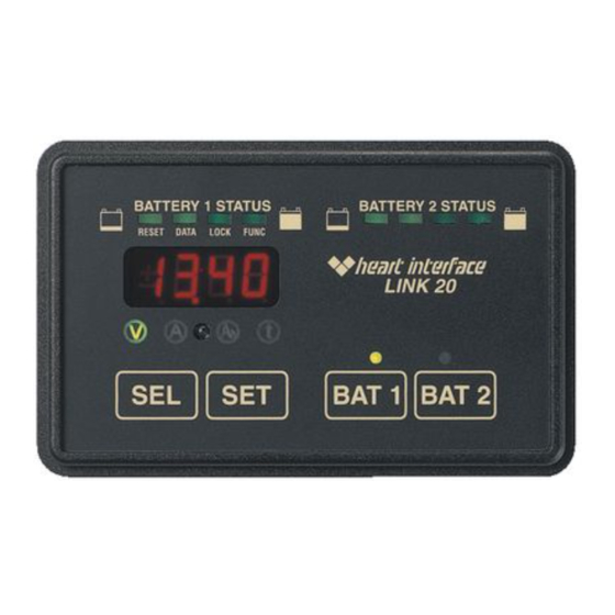
LINK 20
INSTALLERS: PLEASE LEAVE THIS MANUAL WITH THE OWNER.
IT CONTAINS IMPORTANT OPERATING INFORMATION.
APPLICATIONS: The Link 20 provides instrumentation of two banks of
batteries. The Link 20 does not control an inverter/charger. For installations
involving a Freedom inverter/charger and two battery banks, the Link 2000
is recommended. If a Freedom inverter/charger and one battery is anticipated,
the Link 1000 is recommended. For instrumentation of a single battery bank
with no inverter/charger controls, the Link 10 is ideal.
OPERATION: Instructions on how to operate your Link 20 begin on page 4
of this manual.
INSTALLATION: This manual contains easy to follow installation instructions
beginning on page 32.
WARRANTY ISSUES: Warranty issues will be resolved directly through Heart
Interface. Please do not route warranty issues through your dealer.
th
Sales\D:\work\link20\link20Revb.pm6
Advertisement
Table of Contents

Summary of Contents for Heart Interface LINK 20
- Page 1 Link 1000 is recommended. For instrumentation of a single battery bank with no inverter/charger controls, the Link 10 is ideal. OPERATION: Instructions on how to operate your Link 20 begin on page 4 of this manual. INSTALLATION: This manual contains easy to follow installation instructions beginning on page 32.
- Page 2 TABLE OF CONTENTS Link 20 Dual Watch Link 20 Link 20 Functions LINK 20 SPECIFICATIONS...
- Page 3 LINK 20 INTRODUCTION Congratulations! Dual Watch Link 20 Link 20 Link 20 POWER CONNECTION WARNINGS Link 20 IMPORTANT BATTERY FACTS Amp-hour (A hr) 20 hour rate Mid-Capacity Rule...
- Page 4 FRONT PANEL OF YOUR LINK 20 Dual Watch...
- Page 5 USING YOUR LINK 20 STATUS LIGHTS potential to do work flow consumed - 6.0 from the battery amount of en- ergy removed from Link 20 Link 20 estimate...
- Page 6 READING THE LIGHT BARS Link 20 Link 20 Percent Full Optional 100% 90-99.9 80-89.9 70-79.9 60-69.9 50-59.9 100% floor 50% floor rate corrected before WE RECOMMEND: Charge your batteries when the Light Bars tell you to!
- Page 7 LINK 20 BATTERY MANAGEMENT Link 20 Mid-Capacity Rule Link 20 Mid-Capacity Rule Mid-Capacity Rule Link 20 Equalizing OVERCHARGE AMP-HOURS Link 20 even after Link 20 This is normal Link 20...
- Page 8 BATTERY CAPACITY TESTING Link 20 CAPACITY AT VARIOUS DISCHARGE RATES (As a percent of 20 hour rate) Hours to Discharge Capacity (percent of rating) 100% Link Link 20 Link 20 USING YOUR INVERTER TO TEST BATTERY CAPACITY...
- Page 9 SYNCHRONIZING TO YOUR BATTERY Link 20 Link 20 Link 20 Link 20 Dual Watch Link 20 Link 20 Link 20 Link 20...
- Page 10 SETUP PROCEDURES Link 20 Set Up Advanced Functions functions functions Advanced tions (see Page 17). variable function hold FACTORY DEFAULT VALUES Monitoring Functions:...
- Page 11 USING SET AND SEL BUTTONS PRESS BAT 1 OR BAT 2 TO PICK THE BATTERY YOU WISH TO SET UP. variable function LIGHT DESCRIPTION Time Remaining Each will light come on in sequence. everything...
- Page 12 WHEN TO SET UP The C Link 20 must Link 20...
- Page 13 HOW TO SET Link 20 13.2 50.0 HOW TO SET Link 20...
- Page 14 HOW TO SET (BATTERY CAPACITY) Link 20 liquid parallel series...
- Page 15 HOW TO SET Link 20 Link 20 INTRODUCTION TO RATE COMPENSATION AND THE PEUKERT EXPONENT Link 20 of the available effective size temporarily decreases...
- Page 16 HOW TO SET UP FUNCTIONS FUNC Link 20 FUNCTIONS TABLE...
- Page 17 Link 20 IMPORTANT!
- Page 18 Link 20 Charged Current % How to Set on page 16.
- Page 19 Link 20 "Mid Capacity Rule rate compensated...
- Page 20 Link 20 Link 20 Link 20...
- Page 22 HOW TO RESET YOUR UNIT RESET RESET To access the RESET functions:...
- Page 23 DATA: YOUR BATTERY HISTORY DATA DATA To access the DATA displays: Charging Efficiency Factor number of CEF Recalculations deepest depth of discharge average depth of discharge What the Historical Information Means: "u" Advanced Function +I999 -i999 i999...
- Page 24 LOCK: KID PROOFING LOCK LOCK Link 20 To access the LOCK:...
- Page 25 SETTING PEUKERT EXPONENT Link 20 BAT 1 BAT 2 Link 20...
- Page 26 HIGH DISCHARGE RATES & PEUKERT'S EQUATION Link 20 [current] [time] [current] [time] Link 20 "n"...
- Page 27 HIGH DISCHARGE RATES & PEUKERT'S EQUATION...
- Page 28 TYPICAL PEUKERT'S EXPONENTS Typical Values for Peukert's Exponent "n" "n" "n" Prevailer & SeaGel Batteries "n" Trojan Batteries "n"...
- Page 29 TYPICAL PEUKERT'S EXPONENTS Surrette and Rolls Batteries "n" "n" CALCULATING PEUKERT'S EXPONENT...
- Page 30 SET UP & HISTORICAL DATA PARAMETER DEFAULT Bat. 1 Bat.2 CHARGED CHARGED D A T A Bat. 1 Bat.2 FUNCTIONS DEFAULT Bat. 1 Bat.2 Link 20...
- Page 31 L I M I T E D W A R R A N T Y LINK DO NOT INSTALL OR ATTEMPT TO USE THIS PRODUCT UNTIL YOU HAVE READ THE OWNER’S MANUAL IN ITS ENTIRETY. IMPROPER INSTALLATION OR USAGE OF THIS DEVICE MAY BE HAZARDOUS AND MAY CAUSE DAMAGE TO OTHER ELECTRI- CAL EQUIPMENT.
- Page 32 READ BEFORE WIRING !!!!! Before wiring the Link 20 , install the shunt as indicated. All wiring should be done before installing the meter power fuse. CAUTION!!!! The output voltage of the shunt is very small. It is critical that all of the connections for the shunt sense leads have the highest possible integrity.
- Page 34 WIRE BY WIRE DETAIL BATTERY COMPARTMENT Link 20 POSITIVE LEADS TO BATTERY SWITCH 1 2 3 1 2 3 4 1 2 3 1 2 3 4 1 2 3 1 2 3 4 1 2 3 4 BAT. 1 BAT.
- Page 35 WIRING CONNECTIONS TO THE Link 20 Make the necessary wire connections to the Link 20 as shown in the following diagram: CAUTION LINK 20 NOTE: BE SURE TO USE TWISTED WIRE FOR GREEN & ORANGE AND YELLOW & BROWN SHUNT SENSE PAIRS.
- Page 36 WIRE BY WIRE CHECK Link 20 Only the shunt may be connected directly to battery negative! Link 20 Link 20...
- Page 37 MOUNTING Link 1000 Thin-Mount Freedom...
- Page 38 REMOVING THE UNIT...
- Page 39 START UP LINK 20 LINK 20 LINK 20 LINK 20 LINK 20...
Need help?
Do you have a question about the LINK 20 and is the answer not in the manual?
Questions and answers
Can I replace the face panel on a heart interface link 20 battery monitor. 27 years old. The lower Right button cracked and pushed in.
I have a heart interface link 20. It is about 27 years old. Still works fine. But the face press points along the bottom are fragile and battery number two button has a hole in it. Can I replace the face panel? If so, what is the cost