Table of Contents
Advertisement
Quick Links
Advertisement
Table of Contents

Summary of Contents for CENTURION SYSTEMS SupaHelix
- Page 1 SupaHelix Installation Manual Centurion Systems (Pty) Ltd www.CentSys.com...
- Page 2 Americas, Australia and the Pacific Centurion Systems (Pty) Ltd reserves the right to make changes to the products described in this manual without notice and without obligation to notify any persons of any such revisions or changes. Additionally, Centurion Systems (Pty) Ltd makes no representations or warranties with respect to this manual.
-
Page 3: Table Of Contents
15 Required Tools and Equipment page 16 Mounting Instructions page 17 6.1. Important Considerations page 17 6.2. Mounting the SupaHelix Programming Console page 17 6.3. Mounting the CP104 Receiver page 19 Wiring Diagrams page 21 Electrical Setup page 23 8.1. - Page 4 Menu 1.2.4. Delete All Remotes page 29 page 29 Menu 1.3. Edit Remote Button Menu 1.4. Count Remotes page 29 Menu 2- Input/Output page 30 Menu 2.1. Setup Channel 1 page 30 Menu 2.2. Setup Channel 2 page 30 Menu 2.3. Setup Channel 3 page 30 Menu 2.4.
- Page 5 Menu 7.2. Upload Logs page 37 Menu 7.3. Delete Logs page 37 Menu 8- Firmware Upgrade page 37 Diagnostics page 38 24 Month Product Warranty page 40 Installation handover page 42 www.CentSys.com page 5...
- Page 6 Detailed installation features and functions are referred to later in this manual. STEP Gather Required Tools and Equipment STEP Heed Necessary Site Considerations STEP Mounting the SupaHelix Programming Console STEP Mounting the CP104 Receiver STEP Cabling and Wiring page 6...
-
Page 7: Electrical Setup
Electrical Setup STEP SupaHelix Configuration Commissioning & Handover STEP Carry out a Professional Handover to Client www.CentSys.com page 7... -
Page 8: Safety First Important Safety Instructions
• Explain these safety instructions to all persons authorised to use SupaHelix, and be sure that they understand the hazards associated with the SupaHelix system • Do not leave packing materials (plastic, polystyrene, etc.) within reach of children as such materials are potential sources of danger •... -
Page 9: Glossary Of Terms
Glossary of Terms Channel: An electrical gateway implemented as a physical terminal on the SupaHelix • that provides the external interface to input or output signals • Input: A potential-free normally-open electrical signal that is linked to an appropriately configured channel to provide an action-inducing stimulus to the SupaHelix Output: A potential-free open collector electrical signal that is generated by an •... - Page 10 Declaration of Conformity This section has been left blank intentionally. page 10 www.CentSys.com...
-
Page 11: General Description
1. General Description The SupaHelix is a three-channel multi-user access control device capable of working with up to 10,000 unique code-hopping remote control buttons. Transmitters can be learned into up to 10,000 individual units, for example a house number, with each unit containing between one and 255 possible sub-units, for example individual tenants. -
Page 12: Icons Used In This Manual
2. Icons Used in this Manual This icon indicates tips and other information that could be useful during the installation. This icon denotes variations and other aspects that should be considered during installation. This icon indicates warning, caution or attention! Please take special note of critical aspects that MUST be adhered to in order to prevent injury. -
Page 13: Specifications
3. Specifications 3.1. Physical Dimensions 29mm 90mm FIGURE 1. OVERALL DIMENSIONS FOR THE SUPAHELIX 67mm 28mm FIGURE 2. OVERALL DIMENSIONS FOR THE CP104 RECEIVER (V3.1 OR LATER) www.CentSys.com page 13... -
Page 14: Technical Specifications
Open Collector - Maximum Current 50mA per Channel Display 2.4 Inch 128 x 64 Transflective with Backlight Housing Material Degree of Protection Programming Console: IP50 CP104 Receiver Supply Voltage 10.5V - 30V DC (Powered Through the SupaHelix) CP104 Operating Frequency 433.92 MHz Sensitivity 110 dBm Degree of Protection CP104 Receiver: IP65 Maximum Distance... -
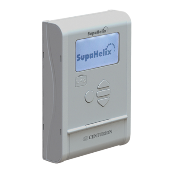
Page 15: Product Identification
4. Product Identification FIGURE 3. PRODUCT IDENTIFICATION 1. SupaHelix Programming Console 6. Removable terminals 2. LCD screen 7. CP104 receiver V3.1(or later) 3. USB port 8. Mounting slots 4. Control interface 9. Mounting bracket for SupaHelix 5. Terminal cover www.CentSys.com page 15... -
Page 16: Required Tools And Equipment
5. Required Tools & Equipment Screwdrivers 3.5mm flat; pozi drive no.2 Pliers Electric drilling machine Silicone sealant Connector Crimping tool block and Pin lugs Measuring Hole saw tape Marking Fasteners pen/chalk Drill bits 5mm masonry; 6mm drill bit Spirit level Hacksaw Extension cord FIGURE 4. -
Page 17: Mounting Instructions
To prevent tampering and potentially compromising the integrity of the system, the SupaHelix Programming Console must be mounted in a secure location. The SupaHelix Programming Console must be mounted in a location where it will not come into direct contact with the elements, preferably indoors or in a suitably sealed enclosure. - Page 18 Mounting M4 pan-head Pozi screws connecting bracket the panel to the mounting bracket. Separate the mounting bracket from the SupaHelix Programming Console. Mounting surface FIGURE 7 Mark the position of the unit on the Fasteners wall.
-
Page 19: Mounting The Cp104 Receiver
Terminal cover Replace the Pozi screws. Screwdriver M4 pan-head Pozi screw FIGURE 10 6.3. Mounting the CP104 Receiver SupaHelix Programming Console CP104 receiver cover Remove the cover from the enclosure using a flat screwdriver. Slot Mounting bracket Screwdriver FIGURE 11 CP104 receiver cover Remove the cover and unclip the circuit board from the retaining clips. - Page 20 Mounting surface Mark the position of the unit on the wall. Using the 5mm masonry bit, drill a Fastener hole into mounting surface wall (for plaster board mounting please follow the instructions provided with the plaster board fasteners). Mounting hole FIGURE 13 Mount the bracket using the fasteners provided.
-
Page 21: Wiring Diagrams
7. Wiring Diagrams Power input 10.5V - 30V DC Channel input/output Receiver communication terminals FIGURE 16. PROGRAMMING CONSOLE Receiver communication terminals FIGURE 17. CP104 RECEIVER (V3.1 OR LATER) www.CentSys.com page 21... - Page 22 (V3.1 or later) Air Conditioner 220V (N) If the unit receives power from the system it is to control, an additional common connection is not necessary FIGURE 18. TYPICAL SUPAHELIX WIRING DIAGRAM TO D10 AND SWITCHING GEYSER page 22 www.CentSys.com...
-
Page 23: Electrical Setup
INPUT filter on Rising Edge FIGURE 20 While setting up the SupaHelix system via the LCD display, all the steps that have to be followed are clearly provided via the display. It is only necessary to note the following: •... -
Page 24: Menu Navigation Map
8.1. Menu Navigation Map Remote Controls 1.1. Add New Remotes 1.1.1. Add Remote 1.1.2. Template Add Remote 1.2. Delete Remotes 1.2.1. Delete Remote Button 1.2.2. Delete Remote by Button 1.2.3. Delete Remotes by Unit 1.2.4. Delete All Remotes 1.3. Edit Remote Button 1.4. - Page 25 Display Options 5.1. Adjust Display Contrast 5.2. Adjust Backlight Intensity 5.3. Adjust Backlight Timeout Security Options 6.1. Menu Locking Logging Options 7.1. View Logs 7.2. Upload Logs 7.3. Delete Logs Firmware Upgrade www.CentSys.com page 25...
-
Page 26: Menu 1- Remote Controls
(for example where two Shift key SupaHelix modules are installed on a site) and likewise a four-button remote control gains two extra buttons and can Press and hold the ‘fourth’... -
Page 27: Menu 1.1. Add New Remotes
Any button can be set to control one or more of the three channels provided by the SupaHelix system. When adding remote controls, it is recommended that a record be kept of the ID number allocated by the system to each respective remote control and the person to whom the remote control is given. -
Page 28: Menu 1.2. Delete Remotes
Menu 1.2.1. Delete Remote Button The operation of a single button of a particular remote control can be cleared. For example, the SupaHelix allows the activation of Channel One set on one remote button to be cleared, without affecting the other operations that the same remote control performs. The remote control is required for this operation. -
Page 29: Menu 1.2.4. Delete All Remotes
• If deleting all the remotes associated with a specific unit number, use the directional arrows to select the unit number (between 0 and 9, 999) and confirm your selection with the oblong button. • If deleting all remotes, it is simply necessary to confirm your selection using the oblong button. Menu 1.2.4. Delete All Remotes Clears the entire memory of learned-in remotes. All remote controls will be removed from the system. Remote controls are not required for this operation. Menu 1.3. -
Page 30: Menu 2- Input/Output
Menu 2 – Input/Output The system is capable of learning up to 10,000 compatible code-hopping remote control buttons. Menu 2.1. Setup Channel 1 Menu 2.1. Setup Channel 2 Menu 2.1. Setup Channel 3 Each channel can be configured as either an input or an output. Inputs are used for monitoring purposes. -
Page 31: Menu 2.4. Change Mappable Output
Basic Function: This feature allows one or more outputs to be triggered upon the activation of the specific input. For example, Input 1 can be configured to activate Outputs 2 and 3 when activated. This is useful in instances where the user wants to create a feedback loop within the system. The SupaHelix automatically determines which outputs are available Menu 2.4. Change Mappable Output This operation changes the default output that new remote controls are programmed to activate. -
Page 32: Menu 3.2. Time Zone
This function allows you to select the time zone and major cities associated within that time zone where the SupaHelix is being installed. Daylight savings are automatically applied to the city selection where applicable. Changing the time zone doesn’t change the set date and time of the unit. -
Page 33: Menu 4.2. Backup And Restore
Parameter Unit Minimum Default Maximum Description Channel direction Input; Output Output Pulsed; Latching; Mode Momentary Momentary Mappable channel Channel 1; 2; 3 Channel 1 LCD backlight 100% brightness LCD backlight timeout Mm:ss 00m:01s 00m:15s 01m:00s LCD contrast Level TABLE 2 Menu 4.2. -
Page 34: Menu 4.2.2. Restore From Usb
Menu 4.2.2. Restore from USB Allows all controller settings, remote controls and phone numbers from a previous backup to be uploaded onto the system. Note that logs will not be restored. If a backup has been created on a USB memory stick Procedure to Restore System Data: 1. -
Page 35: Menu 5- Display Options
When selected, this option initiates a series of diagnostic tests to query the system’s health and operation of the following system components: 1. All three input/output channels. 2. The up, down and ‘back’ buttons. 3. The receiver. 4. The onboard buzzer. 5. -
Page 36: Menu 6- Security Options
Menu 6 – Security Options Menu 6.1. Menu Locking Various options are available to limit access to the menu and help prevent tampering of the unit and unwanted altering of the settings. 1. No security – the menu is accessible to anyone. 2. -
Page 37: Menu 7.2. Upload Logs
USB device. Place this file on the root directory of the USB key you intend to use. After the new firmware has been installed, the SupaHelix will request a confirmation. FIGURE 31 www.CentSys.com page 37... -
Page 38: Diagnostics
9. Diagnostics The SupaHelix system provides useful visual diagnostic feedback of the overall system health via a series of diagnostic screens which are easily accessible from the main screen by pressing either of the directional arrows. To get back to the main screen just keep scrolling through the screens using the directional arrows. - Page 39 Supp Voltage: This is the • current supply voltage read by the system as provided by the power source Pup: The date and time that the • device was last powered up • Pdn: The date and time that the device was last powered down •...
-
Page 40: Month Product Warranty
4. Has been repaired by any workshop and / or person NOT previously authorised by the manufacturer. 5. Has been repaired with components not previously tested, passed or authorised by Centurion Systems (Pty) Ltd, South Africa or one of its subsidiary companies. page 40 www.CentSys.com... - Page 41 Any warranty may be voidable on any equipment which: 1. There has been a failure to install the product in accordance with the installation instructions provided by the manufacturer, or 2. A failure to abide by the safety instructions provided by the manufacturer, or 3.
-
Page 42: Installation Handover
Once the installation has been successfully completed and tested, it is important for the installer to explain the operation and safety requirements of the system. NEVER ASSUME THE USER KNOWS HOW TO SAFELY OPERATE THE SUPAHELIX DEVICE. Neither Centurion Systems (Pty) Ltd, nor its subsidiaries, accepts any liability caused by improper use of the product, or for use other than that for which the product was intended. - Page 43 Notes www.CentSys.com page 43...
- Page 44 After Hours International Technical Support Call Centre +27 11 699 2481 (16:00 to 02:00 - Australian Eastern Time) E&OE Centurion Systems (Pty) Ltd reserves the right to change any product without prior notice All product and brand names in this document that are accompanied by the ®...
Need help?
Do you have a question about the SupaHelix and is the answer not in the manual?
Questions and answers