Table of Contents
Advertisement
Quick Links
TomoScan FOCUS LT
Phased Array Data Acquisition Instrument
User's Manual
This instruction manual contains essential information on how to use this Olympus product safely and effectively.
Before using this product, thoroughly review this instruction manual. Use the product as instructed.
Keep this instruction manual in a safe, accessible location.
DMTA041-01EN [U8778479] — Rev. C
May 2014
Advertisement
Chapters
Table of Contents
Troubleshooting

Summary of Contents for Olympus TomoScan FOCUS LT
- Page 1 DMTA041-01EN [U8778479] — Rev. C May 2014 This instruction manual contains essential information on how to use this Olympus product safely and effectively. Before using this product, thoroughly review this instruction manual. Use the product as instructed. Keep this instruction manual in a safe, accessible location.
- Page 2 Olympus Scientific Solutions Americas, 48 Woerd Avenue, Waltham, MA 02453, Copyright © 2009, 2014 by Olympus. All rights reserved. No part of this publication may be reproduced, translated, or distributed without the express written permission of Olympus. This document was prepared with particular attention to usage to ensure the accuracy of the information contained therein, and corresponds to the version of the product manufactured prior to the date appearing on the title page.
-
Page 3: Table Of Contents
DMTA041-01EN [U8778479], Rev. C, May 2014 Table of Contents Table of Contents ..................... iii Labels and Symbols ................... 1 Important Information — Please Read Before Use ........5 Intended Use .......................... 5 Instruction Manual ........................ 5 Instrument Compatibility ..................... 5 Repair and Modification ....................... - Page 4 Auto-Boot on DC Power ................30 2.5.3 Auto-UT Mode ....................30 3. Operation Overview .................. 31 Hardware Configuration ..................31 TomoScan FOCUS LT Main Unit ................32 Workstation ........................ 32 Ethernet Link ......................33 4. Maintenance and Troubleshooting ............35 Preventive Maintenance ................... 35 Instrument Cleaning ....................
- Page 5 DMTA041-01EN [U8778479], Rev. C, May 2014 DC IN Connector ...................... 63 ETHERNET Connector .................... 64 P Connectors ......................65 UT PHASED ARRAY Connector ................66 List of Figures ....................67 List of Tables ..................... 69 Index ........................71 Table of Contents...
- Page 6 DMTA041-01EN [U8778479], Rev. C, May 2014 Table of Contents...
-
Page 7: Labels And Symbols
Safety-related labels and symbols are attached to the instrument at the locations shown in Figure i-1 on page 1. If any or all of the labels or symbols are missing or illegible, please contact Olympus. Location of rating label (see Table 1 on page 2). -
Page 8: Table 1 Content Of The Rating Label
The CE marking is a declaration that this product conforms to all the applicable directives of the European Community. See the Declaration of Conformity for details. Contact your Olympus representative for more information. The WEEE symbol indicates that the product must not be disposed of as unsorted municipal waste, but should be collected separately. - Page 9 DMTA041-01EN [U8778479], Rev. C, May 2014 Table 1 Content of the rating label (continued) SERIAL The serial number is a nine (9) digit number in the following format: yynnnddmm where: Production year Unit number manufactured that day Production day Production Month For example, the 080011612 serial number indicates that the first unit (001) was produced on the December 16, 2008.
- Page 10 DMTA041-01EN [U8778479], Rev. C, May 2014 Labels and Symbols...
-
Page 11: Important Information - Please Read Before Use
The TomoScan FOCUS LT is designed to perform nondestructive inspections on industrial and commercial materials. Do not use the TomoScan FOCUS LT for any purpose other than its intended use. It must never be used to inspect or examine human or animal body parts. -
Page 12: Repair And Modification
Repair and Modification The TomoScan FOCUS LT does not contain any user-serviceable parts. Opening the instrument might void the warranty. In order to prevent human injury and/or equipment damage, do not disassemble, modify, or attempt to repair the instrument. -
Page 13: Safety Signal Words
DMTA041-01EN [U8778479], Rev. C, May 2014 Safety Signal Words The following safety symbols might appear in the documentation of the instrument: The DANGER signal word indicates an imminently hazardous situation. It calls attention to a procedure, practice, or the like, which, if not correctly performed or adhered to, will result in death or serious personal injury. -
Page 14: Safety
DMTA041-01EN [U8778479], Rev. C, May 2014 The NOTE signal word calls attention to an operating procedure, practice, or the like, which requires special attention. A note also denotes related parenthetical information that is useful, but not imperative. The TIP signal word calls attention to a type of note that helps you apply the techniques and procedures described in the manual to your specific needs, or provides hints on how to effectively use the capabilities of the product. -
Page 15: Battery Precautions
Service instructions, when applicable, are for trained service personnel. To avoid the risk of electric shock, do not perform any work on the instrument unless qualified to do so. For any problem or question regarding this instrument, contact Olympus or an authorized Olympus representative. Electrical Warnings •... -
Page 16: Equipment Disposal
The CR battery contains perchlorate material, and special handling may be required. Refer to http://www.dtsc.ca.gov/hazardouswaste/perchlorate. Equipment Disposal Before disposing of the TomoScan FOCUS LT, check your local laws, rules, and regulations, and follow them accordingly. WEEE Directive In accordance with European Directive 2002/96/EC on Waste Electrical... -
Page 17: Technical Support
Retain packing materials, waybills, and other shipping documentation needed in order to file a damage claim. After notifying the carrier, contact Olympus for assistance with the damage claim and equipment replacement, if necessary. - Page 18 DMTA041-01EN [U8778479], Rev. C, May 2014 Important Information — Please Read Before Use...
-
Page 19: Introduction
The TomoScan FOCUS LT uses phased array and conventional ultrasound to perform nondestructive inspections. It is designed to be controlled using the TomoView software, which can manage up to three TomoScan FOCUS LT instruments in parallel. Key Features TomoScan FOCUS LT instrument’s key features include:... -
Page 20: Table 2 Possible Tomoscan Focus Lt Configurations
Table 2 Possible TomoScan FOCUS LT configurations 16 focusing channels 32 focusing channels 64 focusing channels — 32:32 — — — 64:64 16:128 32:128 64:128 For the complete description of the different TomoScan FOCUS LT model numbers, please refer to “Operating Specifications” on page 42. Introduction... -
Page 21: Instrument Overview
This chapter describes the front and back panels of the TomoScan FOCUS LT. Front Panel Description Figure 1-1 on page 16 shows the front panel of the TomoScan FOCUS LT. This panel enables the user to perform the following: •... -
Page 22: Figure 1-1 The Tomoscan Focus Lt Front Panel
This connector provides a power supply voltage of ±12 VDC rated at 1 A for external devices. DC IN This connector allows the TomoScan FOCUS LT to be supplied from a DC power source. The connector accepts voltages in the range of 15 VDC to 24 VDC, DC IN rated at 5 A. - Page 23 DMTA041-01EN [U8778479], Rev. C, May 2014 When this indicator light is off, it indicates that the conventional ultrasound mode is disabled. The 15 V to 24 V requirement is the voltage needed at the connector site. The DC IN length of the cable has an impact on the power supply’s nominal value. For example, with a nominal value of 15 V and 30 meters of cable, the voltage at the connector site could be lower than 14 V, which is too low for the instrument to start up.
- Page 24 DMTA041-01EN [U8778479], Rev. C, May 2014 defective and requires servicing. If the input voltage is found to be within limits, see “Technical Support” on page 11. If both the AC and DC sources are connected and powered, the instrument automatically operates from the AC input and the DC input is disabled. STBY The letters stand for standby.
- Page 25 Two handles are located on each side of the front panel. They are used to disassemble and reassemble the unit. The front panel handles should not be used to carry the TomoScan FOCUS LT. Because the handles were not designed to transport the instrument, they may break off.
-
Page 26: Back Panel Description
Protective bumper Figure 1-2 Protective bumper of the front panel Back Panel Description Figure 1-3 on page 20 shows the back panel of the TomoScan FOCUS LT. This panel enables the user to perform the following: • Connect the TomoScan FOCUS LT to an AC power source •... - Page 27 Fuse and fuse holder • A fuse holder contains the instrument main fuse. This fuse is used to protect the TomoScan FOCUS LT from an external power surge or from an internal short circuit. • The fuse holder also contains a spare fuse in a small compartment if a fuse replacement is required (for details, see chapter “Maintenance and...
- Page 28 Using fuses that are not recommended can cause a fire hazard. External ground ( ) This ground terminal can be used to ground the TomoScan FOCUS LT using an external wire. This terminal is very useful for certain inspections when it is recommended to ground the instrument with the part under inspection.
-
Page 29: Figure 1-4 Protective Bumpers Of The Back Panel
Protective bumpers Figure 1-4 Protective bumpers of the back panel Do not leave the TomoScan FOCUS LT vertical on the bumpers of the back panel, because the high center of gravity could make it unstable and likely to fall over. - Page 30 DMTA041-01EN [U8778479], Rev. C, May 2014 Chapter 1...
-
Page 31: System Installation
DMTA041-01EN [U8778479], Rev. C, May 2014 2. System Installation This chapter explains the procedures for installing the TomoScan FOCUS LT and for connecting the system components and peripherals to the main instrument. Standard Equipment The packing list should include the following items: •... -
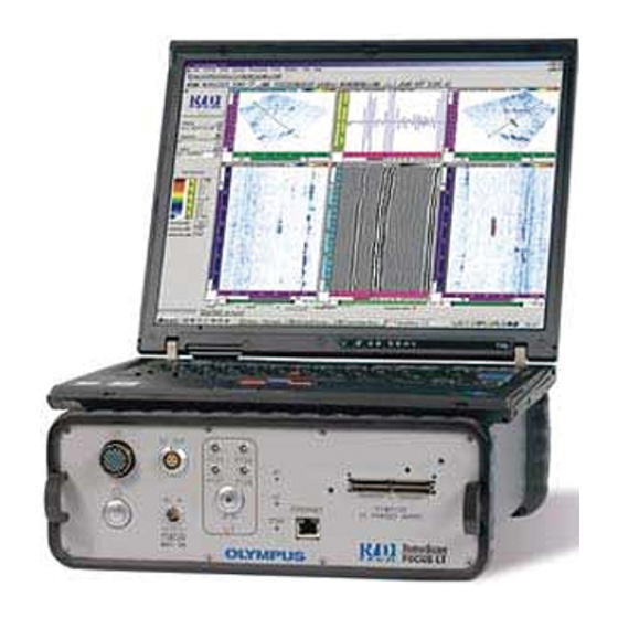
Page 32: Figure 2-1 The Tomoscan Focus Lt Instrument
5 cm (2 in.) to allow for heat dissipation. Do not leave the TomoScan FOCUS LT vertical on the bumpers of the back panel, because the high center of gravity could make it unstable and likely to fall over. -
Page 33: Instrument Connection
The instrument must be connected according to the manufacturer’s instructions in order to prevent risk of electric shock. The TomoScan FOCUS LT must always be completely inserted into its housing and the front panel screws properly tightened in order to ensure proper grounding of the instrument. -
Page 34: Probe Connection
When using a DC power source, connect the power cord to the connector of DC IN the TomoScan FOCUS LT front panel. Connect the other end of the power cord to a suitable DC power source. Turn on the TomoScan FOCUS LT by pressing the front panel on/off switch. -
Page 35: Automatic Startup Modes
2.5.1 Auto-Boot on AC Power Use the auto-boot on AC power mode to remotely turn on a TomoScan FOCUS LT from an AC power source. When this mode is enabled, you do not need to press the front-panel on/off switch ( ) to start the TomoScan FOCUS LT. -
Page 36: Auto-Boot On Dc Power
Use the auto-UT mode to define the state of the button on the front panel when UT ON AC or DC power is applied to the TomoScan FOCUS LT. The mode is disabled by default. To toggle the state of the auto-UT mode Turn off the TomoScan FOCUS LT instrument and disconnect the power cord. -
Page 37: Operation Overview
FOCUS LT is controlled by a computer called the Workstation. This workstation controls the acquisition process and analyzes the ultrasonic data collected by the instrument. Hardware Configuration Figure 3-1 on page 31 shows the hardware architecture of the TomoScan FOCUS LT. 100BASE-T TomoScan FOCUS LT 2 quadrature-type position... -
Page 38: Tomoscan Focus Lt Main Unit
Control the acquisition and receive data from the TomoScan FOCUS LT through an Ethernet link • Process and display UT data collected by the TomoScan FOCUS LT for analysis • Save the UT acquisition data acquired during an inspection on files stored on... -
Page 39: Ethernet Link
Once booted, the internal RPC (remote procedure call) server of the TomoScan FOCUS LT connects to the workstation (that is, the client) through the Ethernet network. For more details on installing and using the acquisition software relating to the TomoScan FOCUS LT, refer to the TomoView Reference Manual. - Page 40 DMTA041-01EN [U8778479], Rev. C, May 2014 Chapter 3...
-
Page 41: Maintenance And Troubleshooting
Instrument Cleaning The external surfaces of the TomoScan FOCUS LT, that is, the housing and the front panel, can be cleaned when needed. This section provides the procedure for the appropriate cleaning of the instrument. -
Page 42: Maintenance Of The Fan Filters
Maintenance of the Fan Filters The TomoScan FOCUS LT is equipped with two cooling fans that are located on the back panel. Filters, located on the vent inlets, remove dust particles from the air drawn in by each fan. To allow sufficient airflow, the filters must be periodically cleaned and changed;... -
Page 43: Cleaning The Fan Filters
Using a compressed-air jet, clean the filter on both sides. Place the filter back in the appropriate position. Screw the four knurled screws back into place. Figure 4-1 Fan filter removed from the TomoScan FOCUS LT 4.3.2 Changing the Fan Filters... -
Page 44: Fuse Changing
The fuse in the power entry module is used only when the TomoScan FOCUS LT is powered by an AC source. When using a DC power source, overload protection is provided by internal voltage limiters inside the instrument. -
Page 45: Figure 4-2 Pulling Out The Fuse Holder From The Tomoscan Focus Lt
Reinsert the fuse holder. The fuse is now replaced, and the TomoScan FOCUS LT should be ready for operation. If the instrument still does not operate after the fuse replacement, refer to a qualified technician. -
Page 46: Troubleshooting
Troubleshooting This section will help you solve minor problems that could occur during the operation of your TomoScan FOCUS LT. Olympus has developed this troubleshooting guide assuming that the instrument has not been modified, and that the cables and connectors are those provided and suggested by Olympus. -
Page 47: Specifications
DMTA041-01EN [U8778479], Rev. C, May 2014 5. Specifications This chapter presents the general specifications (size, operating temperature, power requirements) of all TomoScan FOCUS LT models. General Specifications This section presents the general specifications of the TomoScan FOCUS LT. Table 5 General specifications Category Specification Value Housing Size (W ×... -
Page 48: Operating Specifications
15 V and 30 meters of cable, the voltage at the connector site could be lower than 14 V which is too low for the instrument to start up. Operating Specifications This section details the operating specifications of the TomoScan FOCUS LT. 5.2.1 Pulser/Receiver Differences and Limitations The pulser/receiver specifications are given by model type. - Page 49 DMTA041-01EN [U8778479], Rev. C, May 2014 • Models with the letter “P” — For law in pitch-and-catch mode: Number of consecutive channels used in a configuration (for the pulsing and receiving channels) ≤ Maximum active channels Example with model FLT32128-P-O: pulsing channels P1 to P16, and receiving channels P17 to P32 —...
-
Page 50: Figure 5-1 Illustration Of Pitch-And-Catch Inspection
Blue elements (K to K + N) are used for emission Red elements (L to L + M) are used for reception L + M K + N Figure 5-1 Illustration of pitch-and-catch inspection Table 6 TomoScan FOCUS LT hardware limitations Model Mode Limit 1 Limit 2... -
Page 51: Specifications Of Models Flt16128-P-O And Flt16128-R-O
DMTA041-01EN [U8778479], Rev. C, May 2014 Table 6 TomoScan FOCUS LT hardware limitations (continued) Model Mode Limit 1 Limit 2 Limit 3 FLT32128-R-O K ≥ 1 N ≤ 31 M ≤ 31 K = L Pulse-echo K ≥ 1 K ≠ L N ≤... -
Page 52: Table 7 Specifications Of Models Flt16128-P-O And Flt16128-R-O
DMTA041-01EN [U8778479], Rev. C, May 2014 Table 7 Specifications of models FLT16128-P-O and FLT16128-R-O (continued) Category Specification FLT16128-P-O FLT16128-R-O Receiver Full-scale input voltage 900 mV pp 815 mV pp (pulse-echo) 550 mV pp (pitch-and-catch) 50 Ω, −0/+10 % 50 Ω, −0/+10 % Input impedance (pulse-echo) 150 Ω, ±10 %... -
Page 53: Specifications Of Models Flt32128-P-O And Flt32128-R-O
DMTA041-01EN [U8778479], Rev. C, May 2014 Table 7 Specifications of models FLT16128-P-O and FLT16128-R-O (continued) Category Specification FLT16128-P-O FLT16128-R-O Beam Scan type Azimuthal and linear forming Active elements Up to 16 Total number of elements Delay-range transmission 0–10 µs, steps of 2.5 ns Delay-range reception 0–10 µs, steps of 2.5 ns Dynamic depth focusing... - Page 54 DMTA041-01EN [U8778479], Rev. C, May 2014 Table 8 Specifications of models FLT32128-P-O and FLT32128-R-O (continued) Category Specification FLT32128-P-O FLT32128-R-O Receiver Full-scale input voltage 900 mV pp 815 mV pp (pulse-echo) 550 mV pp (pitch-and-catch) 50 Ω, −0/+10 % 50 Ω, −0/+10 % Input impedance (pulse-echo) 150 Ω, ±10 %...
-
Page 55: Specifications Of Models Flt64128-P-O And Flt64128-R-O
DMTA041-01EN [U8778479], Rev. C, May 2014 Table 8 Specifications of models FLT32128-P-O and FLT32128-R-O (continued) Category Specification FLT32128-P-O FLT32128-R-O Beam Scan type Azimuthal and linear forming Active elements Up to 32 Total number of elements Delay-range transmission 0–10 µs, steps of 2.5 ns Delay-range reception 0–10 µs, steps of 2.5 ns Dynamic depth focusing... - Page 56 DMTA041-01EN [U8778479], Rev. C, May 2014 Table 9 Specifications of models FLT64128-P-O and FLT64128-R-O (continued) Category Specification FLT64128-P-O FLT64128-R-O Receiver Full-scale input voltage 900 mV pp 815 mV pp (pulse-echo) 550 mV pp (pitch-and-catch) 50 Ω, −0/+10 % 50 Ω, −0/+10 % Input impedance (pulse-echo) 150 Ω, ±10 %...
-
Page 57: Specifications Of Models Flt3232-P-O And Flt6464-P-O
DMTA041-01EN [U8778479], Rev. C, May 2014 Table 9 Specifications of models FLT64128-P-O and FLT64128-R-O (continued) Category Specification FLT64128-P-O FLT64128-R-O Beam Scan type Azimuthal and linear forming Active elements Up to 64 Total number of elements Delay-range transmission 0–10 µs, steps of 2.5 ns Delay-range reception 0–10 µs, steps of 2.5 ns Dynamic depth focusing... - Page 58 DMTA041-01EN [U8778479], Rev. C, May 2014 Table 10 Specifications of models FLT3232-P-O and FLT6464-P-O (continued) Category Specification FLT3232-P-O FLT6464-P-O Receiver Full-scale input voltage 700 mV pp 50 Ω, −0/+10 % Input impedance Gain setting range 0 dB to 74 dB in steps of 0.1 dB ±0.5 dB (0 dB ≤...
-
Page 59: Specifications Of Conventional Ut Channels
) to connect P125 P126 P127 P128 conventional probes to the TomoScan FOCUS LT, which correspond to the last four channels of the connector. UT PHASED ARRAY The specifications for these channels are the same ones as the specifications for the phased array channels. -
Page 60: Specifications Of Recorded Data
DMTA041-01EN [U8778479], Rev. C, May 2014 Specifications of Recorded Data Table 11 Specifications of recorded data Category Specification Value Data acquisition Digitizing frequency 1.5625, 3.125, 6.25, 12.5, 25, 50, and 100 MHz, and processing resolution of 8 bits or 12 bits A-scan length 32 to 8192 samples Acquisition depth... -
Page 61: Specifications Of The Ethernet Link
3 alarms available Specifications of the Ethernet Link The TomoScan FOCUS LT must be linked to the workstation with a category 5e Ethernet cable made of unshielded twisted pairs. The maximum cable length depends on the link speed (see Table 12 on page 55). -
Page 62: Safety Standards
Safety Standards This section describes the TomoScan FOCUS LT specifications regarding the safety standards. The TomoScan FOCUS LT is an instrument of Class 1 and overvoltage category II. European directives and standards • The “CE” marking indicates conformity with the essential requirements of the applicable directives of the European Union, that is, the Low Voltage Directive (2006/95/EC) and the EMC Directive (2004/108/EC). - Page 63 DMTA041-01EN [U8778479], Rev. C, May 2014 Electrical Equipment for Measurement, Control and Laboratory Use, Part 1: General Requirements. • This Class A digital apparatus complies with Canadian ICES-001. This equipment has been tested and found to comply with the limits for a Class A digital device, pursuant to part 15 of the FCC Rules.
- Page 64 DMTA041-01EN [U8778479], Rev. C, May 2014 Chapter 5...
-
Page 65: Connector References
DMTA041-01EN [U8778479], Rev. C, May 2014 6. Connector References This chapter presents the technical description of the TomoScan FOCUS LT front panel connectors. For each connector, you will find the following information: a brief description, the manufacturer number, the number of the corresponding cable connector, an illustration, and a table giving the specifications or the signal pinouts for the connector. -
Page 66: I/O Connector
DMTA041-01EN [U8778479], Rev. C, May 2014 I/O Connector Description 18-pin, female, shell 14 Manufacturer; number ITT Cannon; KPT02A14-18S Olympus; 21AN0005 [U8902976] Suggested cable connector; number ITT Cannon; KPT06B14-18P Olympus; 21AN0011 [U88780063] Figure 6-1 The connector Table 13 Pinout for the... -
Page 67: Table 13 Pinout For The I / O Connector
DMTA041-01EN [U8778479], Rev. C, May 2014 Table 13 Pinout for the connector (continued) Signal Signal Description Type length Input Din1 Programmable input. >= 50 µs Can be configured as preset encoder 1 from Preset1 TomoView software. Input Din3 Programmable input. Can be configured as As long pause acquisition from the TomoView as pause... -
Page 68: Dc Out Connector
If the required DIN signal is greater than 50 µs, then maximum PRF will be lower than 10 kHz. Figure 6-2 The Trig on Dout 2 for a signal of 50R DC OUT Connector Description 5-pin, female connector Manufacturer; number LEMO; HGG.2B.305.CLLP Olympus; 21AB0109 [U8908897] Chapter 6... -
Page 69: Dc In Connector
No connection — Ground — No connection — No connection DC IN Connector Description 2-pin, male connector Manufacturer; number W.W. Fischer Inc.; D.103.Z051-60 Olympus; 21AB0321 [U8902550] Suggested cable connector; number W.W. Fischer Inc.; S.103.Z051-130 Olympus; 21AB0322 [U8908014] Connector References 63... -
Page 70: Ethernet Connector
15 VDC to 24 VDC input, rated at 5 A. — Ground ETHERNET Connector Description 8-position modular, female connector Manufacturer; number Stewart Connector; SS-650810SAFLS Olympus; 21AI0080 Suggested cable connector; number Stewart Connector; 940SP-360808 Olympus; 21AI0079 Pin 1 Pin 8 Figure 6-5 The connector... -
Page 71: P Connectors
No connection P Connectors Description Female, coaxial Manufacturer; number LEMO; SWH.00.250.CTHV Equivalent: W.W. Fischer Inc.; WDE.101.A004 Olympus; 21AB0107 [U8831532] Suggested cable connector; number LEMO; FFC.00.250.CTAC31 Equivalent: W.W. Fischer Inc.; S.101.A004/3.0 Olympus; 21AB0016 [U8907038] Figure 6-6 The connectors Connector References 65... -
Page 72: Ut Phased Array Connector
128 connectors, the voltage present on the P connectors can be dangerous as a shock hazard. UT PHASED ARRAY Connector Description 160-pin, female, Minidock-type connector Manufacturer; number Global Components; 30033-160T Olympus; 21AI0170 [U8904017] Suggested cable connector; number Framatome; 89649-002 Olympus; 21AI0153 [U8906010] Chapter 6... -
Page 73: List Of Figures
Fan filter removed from the TomoScan FOCUS LT ........37 Figure 4-2 Pulling out the fuse holder from the TomoScan FOCUS LT ....... 39 Figure 4-3 Fuse and spare fuse locations (fuse holder pulled out - side view) ... 40 Figure 5-1 Illustration of pitch-and-catch inspection ............ - Page 74 DMTA041-01EN [U8778479], Rev. C, May 2014 List of Figures...
-
Page 75: List Of Tables
DMTA041-01EN [U8778479], Rev. C, May 2014 List of Tables Table 1 Content of the rating label ..................2 Table 2 Possible TomoScan FOCUS LT configurations ..........14 Table 3 Fuse rating according to power supply voltage ..........39 Table 4 Troubleshooting guide ..................40 Table 5 General specifications ................... - Page 76 DMTA041-01EN [U8778479], Rev. C, May 2014 List of Tables...
-
Page 77: Index
DMTA041-01EN [U8778479], Rev. C, May 2014 Index AC (alternating current) 17 cable part number, crossover 33 indicator light 17 Canadian and U.S. standards 56 AC power 29 CAUTION signal word 7 AC power requirements, specifications 42 cautions air outlets 22 See also warnings 19 architecture, hardware network 31 connecting probes 28... - Page 78 DMTA041-01EN [U8778479], Rev. C, May 2014 Ethernet DC OUT pinout 63 cable 55, 56 technical references 62 connector 18, 64, 65 link 33 ETHERNET pinout 65 European directives and standards 56 technical references 64 external ground 22 pinout 60 fan filters technical references 60 changing 37 LEMO 01 3...
- Page 79 25 Ethernet link 33 installation, system hardware network architecture 31 connecting probes 28 TomoScan FOCUS LT instrument 32 connecting the instrument 27 workstation 32 installing the instrument 25 NOTE signal word 8 standard equipment 25...
- Page 80 19, 21 pulser/receiver specifications 42 recommended fuses 22, 39 FLT16128-P-O 45 voltage on LEMO connectors 17, 53 FLT16128-R-O 45 numbers description, TomoScan FOCUS LT FLT32128-P-O 47 model 42 FLT32128-R-O 47 FLT3232-P-O 51 FLT64128-P-O 49 Olympus technical support 11...
- Page 81 DMTA041-01EN [U8778479], Rev. C, May 2014 signal words information notes 7 TCG, specifications 54 IMPORTANT 7 technical support 11 NOTE 8 terminal, ground 22 TIP 8 Time-Corrected Gain, specifications 54 safety 7 TIP signal word 8 CAUTION 7 troubleshooting 40 DANGER 7 changing the fuse 38 WARNING 7...
- Page 82 DMTA041-01EN [U8778479], Rev. C, May 2014 Index...
Need help?
Do you have a question about the TomoScan FOCUS LT and is the answer not in the manual?
Questions and answers