
Related Manuals for Applied Omni Series

Summary of Contents for Applied Omni Series
- Page 1 Omni DMX Splitter User Manual Omni 1x5, 1x10 & 2x5 Applied Electronics 722 Bluecrab Rd. Newport News, VA 23606 800-883-0008 appliednn.com Omni DMX Splitter V1.01 1/31/19...
- Page 2 INTRODUCTION: Thank you for purchasing an Applied Electronics Omni DMX splitter. The Omni line has been designed, built and tested with pride in the USA. Your Omni splitter comes with a 5 year warranty and has been constructed to endure years of use in the rough and tumble entertainment environment.
-
Page 3: Power Input
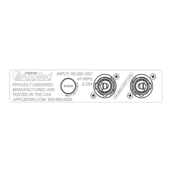
Power input Power input, loop-thru & fuse connections Your Omni DMX splitter is equipped with a universal power supply which will • allow it to operate on input voltages of 85-250 VAC @ 47-66Hz. A 1 amp 250V fuse (3AB 1/4”x1-1/4” style) is provided for protection of internal •... -
Page 4: Termination Switch
Termination switch When engaged the termination switch places a 120ohm resistor between pin number 2 & 3 of the 5 pin input XLR connector. This resistor prevents data reflection back down the transmission line. The terminator should only be engaged when no other devices are connected to the loop-out data connector. If other devices are connected to the loop-out connector the last device should be appropriately terminated. -
Page 5: Troubleshooting
Please feel free to call Applied Electronics for tech support at any time. (800) 883-0003 When checking data issues it is helpful to have a known working device (dimmer, LED light etc) to test with. - Page 6 Repair Shorted cables, faulty fixtures and accidents do occur, so it is possible that at some point in the life of your splitter a data port may be subjected to voltages or currents that exceed the capacity of the built in protection. In that case a receiver/transmitter or optical isolation data chip may be damaged.
-
Page 7: Technical Details
6. Gently press the spare chip until it seats fully in the socket, being careful not to bend any leads 7. Replace the top cover 8. Re-test the unit for correct operation Output PCB Technical Details System Block Diagram Omni DMX Splitter V1.01 1/31/19... -
Page 8: Xlr Connectors
Omni 1x5 Omni 1x10 Omni 2x5 Power input connector Neutrik powerCON 20A NAC3MPA-1 Power loop-thru connector Neutrik powerCON 20A NAC3MPB-1 Input power 85-250 VAC @ 47-66Hz Max loop-thru power 10A @ 250 VAC Power consumption Input fuse 3AB 1/4”x1-1/4” style) MAX 1A 250V ( Number of DMX inputs Number of DMX loop-outs... -
Page 9: Shipping Policy
(5) years from date of shipment. Defects in workmanship or materials becoming evident within the warranty period will be repaired by Applied at no cost for parts or labor to the customer. Applied reserves the right to replace any product or part with the same or equivalent item rather than repair it.
Need help?
Do you have a question about the Omni Series and is the answer not in the manual?
Questions and answers