Advertisement
Quick Links
Pi Supply
The Maker Emporium
https://learn.pi-supply.com
Pi PoE Switch HAT Quick Start And FAQ
Getting started
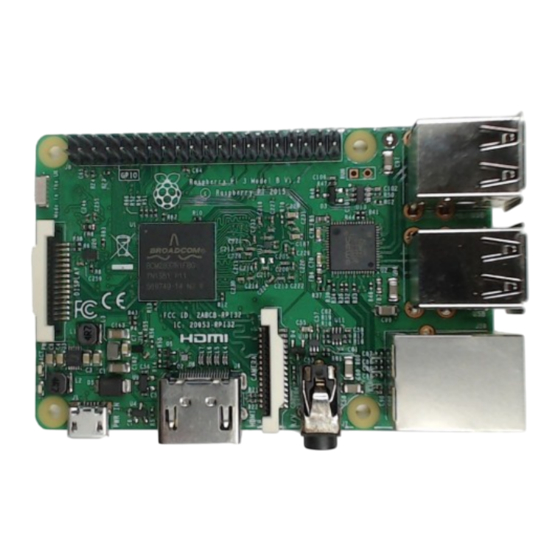
The Pi PoE Switch HAT is an add on board for the Raspberry Pi that brings the Pi Supply Switch
technology together with PoE all in one fantastic package! You can now power your Raspberry Pi
and provide an Ethernet connection in any location with just a single cable. Perfect for removing
the clutter of wires and for reliable use in remote locations.
This guide will show you how to assemble the Pi PoE Switch HAT, set it up in its case and discuss
some of the most common issues and questions.
Kit contents
1 / 22
Advertisement

Summary of Contents for Pi Supply Pi PoE Switch HAT
- Page 1 This guide will show you how to assemble the Pi PoE Switch HAT, set it up in its case and discuss some of the most common issues and questions.
-
Page 2: Board Assembly
Pi Supply The Maker Emporium Inside the box you should have received the following items: https://learn.pi-supply.com 1 Pi PoE Switch HAT board 8 Plastic bolts 4 Plastic spacers 1 Ethernet cable 2 SMD resistors 3 Stickers 1 Info card Board Assembly Step 1 - Unpack your Raspberry Pi. - Page 3 Pi Supply The Maker Emporium https://learn.pi-supply.com plastic bolt will oppose less resistance during assembly. Step 3 - Get the Pi PoE from its anti-static bag. 3 / 22...
- Page 4 Pi Supply The Maker Emporium https://learn.pi-supply.com Step 4 - Place the Pi PoE on top of the Raspberry Pi by gently pushing the female header onto the Raspberry Pi male header. 4 / 22...
- Page 5 Pi Supply The Maker Emporium https://learn.pi-supply.com Step 5 - Screw the last 4 plastic bolts to hold the Pi PoE HAT in place. 5 / 22...
- Page 6 Pi Supply The Maker Emporium https://learn.pi-supply.com If you have acquired the Pi PoE case for this product please skip to the next Section – Pi PoE Switch HAT Case assembly otherwise connect the Ethernet cables as shown in the picture.
-
Page 7: Case Assembly
Case Assembly Pi PoE Switch HAT Case is the prefect enclosure for the Pi PoE Switch HAT and the Raspberry Pi. It has been designed so that it can still allow access to the power button. 7 / 22... - Page 8 Pi Supply The Maker Emporium https://learn.pi-supply.com Step 1 - After removing the protective plastic pull gently out the two sides of the bottom part of the case to unhook the top. 8 / 22...
- Page 9 Pi Supply The Maker Emporium https://learn.pi-supply.com This should allow you to detach the top cover and easily take a part the case. Within the case you will find 4 rubber feet and a plastic bit used to provide access to the Pi PoE power button.
- Page 10 Pi Supply The Maker Emporium https://learn.pi-supply.com Step 2 - Insert the plastic button extender through the hole of the top part of the case. 10 / 22...
- Page 11 Pi Supply The Maker Emporium https://learn.pi-supply.com Step 3 – To install the rubber feet on the bottom part of the case you will either have to push and twist them through one of the 4 the holes or help yourself with a small screwdriver to tuck in the top part of the feet within the hole as shown on the left.
- Page 12 Pi Supply The Maker Emporium https://learn.pi-supply.com Step 4 - Insert the Raspberry Pi and the Pi PoE in the bottom part of the case by first placing the USB connectors in. 12 / 22...
- Page 13 Pi Supply The Maker Emporium https://learn.pi-supply.com The PCBs of the two boards should be aligned within the grooves of the panel as shown in the picture. 13 / 22...
- Page 14 Pi Supply The Maker Emporium https://learn.pi-supply.com Step 5 - Take the small Ethernet cable and connect it between the Raspberry Pi and the Pi PoE. 14 / 22...
- Page 15 Pi Supply The Maker Emporium https://learn.pi-supply.com Step 6 - Connect the Ethernet cable coming from the PoE switch or from the injector. 15 / 22...
- Page 16 Pi Supply The Maker Emporium https://learn.pi-supply.com Step 7 - Slide the top part of the case back in place. As you do that gently pull out each side of the top part of the case so to allow the connectors of the Raspberry Pi to slot into place.
- Page 17 Pi Supply The Maker Emporium https://learn.pi-supply.com At this point the Pi PoE Switch HAT is ready to be used. Note that the case has been designed with wall fixing features. 17 / 22...
- Page 18 Pi Supply The Maker Emporium https://learn.pi-supply.com Button, Jumper and Solder PAD Button - SW1 To start the Raspberry Pi press SW1 for 2 seconds. To completely remove power to the Raspberry Pi press SW1 for at least 15 seconds and until the red LED of the Pi will switch off.
- Page 19 Pi Supply The Maker Emporium https://learn.pi-supply.com On the reverse of the board you can find a solder pad to allow you to add flexibility to the Pi PoE by for example use a custom made button to power on and off the Pi PoE.
- Page 20 Pi Supply The Maker Emporium https://learn.pi-supply.com To drive the LEDs you will have to set the GPIOs as outputs. The LED on the left is a single green LED whereas the one on the right is a dual green/amber LED. To drive the green LED on the left it is sufficient to pull the corresponding GPIO 23 high, to turn it bring the GPIO low.
- Page 21 I cannot install an additional board on the pass-trough header The Pi PoE Switch HAT comes with a pass through header so that additional board can be stacked on top of it. In some cases thought you will need to use an...
- Page 22 Pi Supply The Maker Emporium https://learn.pi-supply.com I'd like to add another board on top, will they conflict? A detailed pinout for the Pi PoE can be seen in the picture below. Please refer to the Raspberry Pi Pinout website where you will be able to verify the pin compatibility with the various cards available from the main vendors.
Need help?
Do you have a question about the Pi PoE Switch HAT and is the answer not in the manual?
Questions and answers