Advertisement
Quick Links
To
system
To
system
Wet
tank
Wet
tank
Air
compressor
Air
compressor
D2
D2
EXH
EXH
UNL
UNL
RES
RES
Vented to atmosphere
619915
Vented to atmosphere
Inlet check
valve open
235
Purge valve
closed
Illustrated cycle shows left side in charge mode
Illustrated cycle shows left side in charge mode
(drying) and right side in regenerating mode;
(drying) and right side in regenerating mode;
process alternates every 90 seconds.
process alternates every 90 seconds.
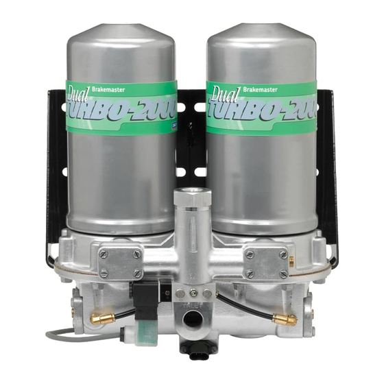
SKF Brakemaster
Dual Turbo-2000 air dryer service schematic
®
Left side
side view
Left side
side view
Left side
side view
238
Check valve
open
during
charge
Check valve
619911
Regeneration
valve open
Regeneration
619915
Inlet check
valve open
Clean / dry air
Clean / dry air
Atmospheric pressure
619915
Inlet check
valve open
235
Purge valve
closed
Left side
Left side
Left side
238
open
during
charge
619911
valve open
619915
Inlet check
valve open
Atmospheric pressure
Dirty / wet charged air
Dirty / wet charged air
Bottom view
Bottom View
619912 MLT 12V
619924 MLT 24V
Bottom view
619912 MLT 12V
619924 MLT 24V
Clean / dry air
Clean / dry air
Dirty / wet charged air
Dirty / wet charged air
Right side
Right side
Right side
619911
619911
closed
235
open
235
open
619110 heater 12V
619110 heater 12V
619111 heater 24V
619111 heater 24V
Dirty / wet purged air
Dirty / wet purged air
Pressurized to
system pressure
Pressurized to
system pressure
valve closed
619915
Inlet check
valve closed
235
Purge valve
open
Atmospheric pressure
Dirty / wet purged air
Right side
side view
Right side
side view
Right side
side view
closed
619915
Inlet check
235
Purge valve
open
Atmospheric pressure
Dirty / wet purged air
Advertisement

Summary of Contents for SKF Brakemaster Dual Turbo-2000
- Page 1 SKF Brakemaster Dual Turbo-2000 air dryer service schematic ® Left side Left side Right side side view Right side side view Left side Left side Right side Right side side view side view Left side Left side Right side side view...
- Page 2 Suite 200 Elgin, IL 60123 1-800-882-0008 Purge valve Purge valve ® SKF is a registered trademark of the SKF Group. open open www.vsm.skf.com © SKF Group 2009 The contents of this publication are the copyright of the publisher and may not be reproduced (even extracts) unless permission is granted.
Need help?
Do you have a question about the Brakemaster Dual Turbo-2000 and is the answer not in the manual?
Questions and answers