
Summary of Contents for Jedmed Horus Scope 39-7420-2P
- Page 1 Horus Scope Control unit 39-7420-2P User Manual Document NO.: pmnl 145 rev. 0 Copyright announcement: Copyright@2015 JEDMED. All right reserved.
-
Page 2: Table Of Contents
Contents Preparations ............................ 3 1.1. Before use ......................... 3 1.2. Introduction of Control Unit ..................... 5 1.3. Charging the battery ......................9 1.4. Power indicator ....................... 10 1.5. Assembling ........................11 1.6. Using the Setup mode ....................12 1.7. Entering the patient ID ....................15 Taking pictures .......................... -
Page 3: Preparations
1. Preparations 1.1. Before use Prior to installation and start-up of Horus scope, carefully read the user manual. As with all technical devices, the proper function and safety operation of this device depends on the user complying with the safety recommendations presented in these operating instructions. In addition, please make sure it does not appear damaged or broken. - Page 4 1.1.3. No compensation for missed shots We cannot compensate for missed shots if technical problems with the camera or card prevent recording. 1.1.4. Also refer to “Usage cautions and notes” Please also refer to “Usage cautions and notes” for more instructions of the battery, SD card, etc. LEASE NOTE THAT THE ACTUAL CONTROLS AND COMPONENTS MENU ITEMS AND OTHER INFORMATION OF YOUR...
-
Page 5: Introduction Of Control Unit
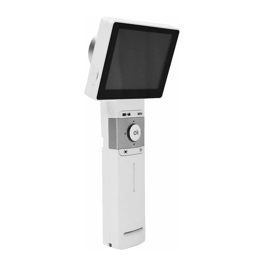
Product Name Model Name Accessories JEDMED Horus 1. Battery Control unit 2. Power adapter 39-7420-2P 3. USB cable 4. AV cable 5. Charging station 6. SD card 7. Foot switch (Optional part) 1.2.3. User interface Control Unit (JEDMED Horus 39-7420-2P) - Page 8 Digital Endoscope Adapter JEDMED Horus Scope 39-7430 An adapter designed to connect the control unit of JEDMED Horus Scope and existing endoscopes in the market. The assembly system (control unit & Horus Scope Adapter & existing endoscope in the market)
-
Page 9: Charging The Battery
1.3. Charging the battery 1.3.1. Always charge before first use Prior to first use, insert the battery into the control unit and close the battery cover referred to the below section. Connect USB connector to the power adapter. Let the battery be charged for at least five hours. -
Page 10: Power Indicator
1.4. Power indicator... -
Page 11: Assembling
1.5. Assembling (Take Digital Eye Fundus Camera as an example.) Step1: Align the marks of the optical lens and control unit. Step2: Hold the optical lens and attach it to the control unit. Rotate and fasten the optical lens in a clockwise direction. You will hear a click when the lens locks into the control unit. -
Page 12: Using The Setup Mode
1.6. Using the Setup mode (Take Digital Eye Fundus Camera as an example.) 1.6.1. Turn on the power To turn on the system, press the power button to turn on the control unit. Approximately one to two seconds later, the boot screen will appear on the LCD panel. Once the LCD panel shows the live image, it takes about 10 seconds for the on-screen display (OSD) to be superimposed. - Page 13 Settings : *Note Some functions are only suitable for Horus Scope Eye Fundus camera. [Aiming Light/Capture Light] (*Digital Eye Fundus Camera only) The default setting of [Aiming Light/Capture Light] is [IR/White LED]. In the setting, Digital Eye Fundus Camera employs IR illumination for alignment and focusing to assure patient comfort. With IR, the user observes fundus images monochromatically.
- Page 14 [UVC] When you connect 39-7420-2P to a computer via USB cable, the product works as a USB storage device. If UVC mode is on, pictures can be shown both on the LCD panel of the product and the screen of the computer. To display image on the computer, please install webcam application prior to enabling UVC mode.
-
Page 15: Entering The Patient Id
[Time Setting] User can change the current time setting from the screen. [Format SD Card] User can format the SD card. NOTE All information will be deleted after SD card is formatted. [Factory Setting] User can recover the device to its factory settings. 1.7. - Page 16 1.7.1. Create a new patient ID from scratch By gently pressing the OK button, the user always goes back to a shooting mode, either photo or video mode; from the top information icons, tap to start the process. 1.7.2. Create a new patient ID on an existing one After a patient ID is set, the user can quickly create a new patient ID that is based on the existing ID plus 1 e.g., ABCD12345 →...
-
Page 17: Taking Pictures
2. Taking pictures 2.1. Sequence of operations Step 1: Turn on the power Press the power button to turn on the control unit. Approximately one to two seconds later, the boot screen will appear on the LCD panel. After about 10 seconds, the information icons will appear on the top of the LCD panel. -
Page 18: Photo Mode
2.2. Photo mode The device’s default setting is “photo mode.” The user can take a picture or video in “photo mode” or “video mode,” respectively. Photo mode: Press down the OK button halfway to focus; press it all the way to take a still picture. Press halfway Press... - Page 19 ARHHMMSS.jpg ARXXXXXHHMMSS.jpg Endoscope Horus Scope EDHHMMSS.jpg EDXXXXXHHMMSS.jpg Adapter Adapter Symbol Refer to Eye fundus camera Left eye photo taken by the eye fundus camera Right eye photo taken by the eye fundus camera Otoscope Left ear photo taken by the Otoscope Right ear photo taken by the Otoscope Dermatoscope Speculum: GI (General Imaging Lens)
-
Page 20: Video Mode
2.3. Video mode Video mode: Completely press the OK button to start recording. Press again to end recording. By using Digital Eye Fundus Camera the default setting of “Aiming Light/Capture Light” is “IR/White LED.” See process below: Press Press fully fully During the video shooting, user can press “the brightness adjustment key +”... -
Page 21: Playback
3. Playback 3.1. Display mode Touch the photo icon and then touch the display icon to see the photos that have been taken. Click the left or right arrow symbols to go to the previous or next photo, respectively. Click the up or down arrow symbol to backward in days or forward in days. -
Page 22: Deleting Pictures
3.3. Deleting pictures Tap the delete icon to delete the image. By using the “delete” functions on your camera, this only changes the file management information and does not completely delete the data from the memory card. When disposing of or transferring your memory cards, we recommend physically destroying them or using commercially available computer data erasing software to completely delete the data from the card. -
Page 23: Miscellaneous
4. Miscellaneous 4.1. Files transferring Transfer images to an electronic device (e.g., personal computer, laptop, or mobile phone) via the USB cable or SD card. 4.2. Viewing on a computer/laptop screen Turn on UVC mode to simultaneously view images both on LCD panel and the computer/laptop screen. - Page 24 autoclave, or UV light. •Do not extend the supplied cables. Do not keep the power cord near any heat source. •When the camera is not in use, please disconnect the power plug and keep it in a safe place. 4.4.2. Charging the battery •The time required for charging varies depending on the conditions of battery usage.
- Page 25 About the slit lamp jig: •Attach the slit lamp jig only to slit lamp equipment that has been qualified by JEDMED. Make sure the jig is completely locked by pushing it downward. The slit lamp jig is only suitable for Digital Eye Fundus Camera of JEDMED.
- Page 26 4.4.6. EMC (electromagnetic compatibility) During installation and operation of the device, observe the following instructions: •Do not use the device simultaneously with other electronic equipment to avoid electromagnetic interference with the operation of the device. • Do not use or stack the device near, on, or under other electronic equipment to avoid electromagnetic interference with the operation of the device.
- Page 27 •It is recommended to clean the optical lens with a cleaning cloth or lens cleaning tissue, such as THORLABS Inc. (www.thorlabs.com) lens cleaning tissue. If a replacement for the eyecup is needed, please contact the manufacturer or retailer. Clean the eyecup before each use: •Disinfect the eyecup with soft cloth moistened with alcohol (70% ethyl alcohol).
- Page 28 •Vibration, sinusoidal: 10 Hz to 500 Hz: 0.5G 30 G, duration 6 ms •Shock: 10 G, duration 6 ms •Bump: NOTE: It is recommended to remove the battery if the device is stored over two weeks. 4.4.11. Regulations •U.S. Federal law restricts this device, 39-7420-2P, to be sold and distributed, and it should be used only by or on the order of a physician.
-
Page 29: Technical Description
4.5. Technical Description Weight (included battery) 238 g (285 g) Focus Auto & manual focus Camera Resolution Camera Resolution 2592 x 1944 pixels Picture Resolution 2560 x 1920 pixels Video Resolution 1280 x 960 pixels LCD Monitor 3.5” Full Color TFT-LCD Touch Panel Image Format JPEG (Photograph) and H.264 (Video) Interface... -
Page 30: Liability
4.6. Liability Manufacturer considers itself responsible for the effects on safety, reliability, and performance of the device only if •Assembly operations, extensions, readjustments, modifications or repairs are carried out by persons authorized. •The electrical installation of the relevant room complies with the requirements. •The equipment is used in accordance with these instructions for use. -
Page 31: Symbols And Standards
4.8. Symbols and standards Symbols Caution must be taken. Read user’s manual before use. Type BF-Indicates the device is classified as a device with a Type BF applied part. The operator is advised to read the instructions of user’s manual. Manufacturer. - Page 32 responsible for the system complying with the requirements of the system standard IEC 60601-1. If in doubt, consult the technical service department of your local representative. EMC (Electromagnetic Compatibility) The device complies with the International Electrotechnical Commission standards (IEC 60601-1-2: 2007) for electromagnetic compatibility as listed in the tables below.
- Page 33 Voltage, dips, short <5% U <5% U Mains power quality should be that of a interruptions and (>95% dip in U (> 95% dip in U typical commercial or hospital environment. voltage variations for 0.5 cycle for 0.5 cycle If the user of the device requires continued on power supply 40% U 40% U...
- Page 34 a Field strengths from fixed transmitters, such as base stations for radio (cellular/cordless) telephones and land mobile radios, amateur radio, AM and FM radio broadcast, and TV broadcast cannot be predicted theoretically with accuracy. To assess the electromagnetic environment due to fixed RF transmitters, an electromagnetic site survey should be considered.
- Page 35 Manufacturer information: JEDMED Instrument Company 5416 JEDMED Court Saint Louis, MO 63129 314-845-3770 www.jedmed.com Certification information: Obelis S.A. Bd. General Wahis 53,1030, Brussels, Belgium...
Need help?
Do you have a question about the Horus Scope 39-7420-2P and is the answer not in the manual?
Questions and answers