Table of Contents
Advertisement
Quick Links
Advertisement
Table of Contents

Subscribe to Our Youtube Channel
Summary of Contents for Nemtek Taut Wire Node
- Page 1 Taut Wire Node Installer Manual...
-
Page 2: Table Of Contents
Table of Contents Introduction Disclaimer NEMTEK Group Outlets Hardware Setup 4.1 Technical Specifications - Node Board 4.2 Technical Specifications - Recommended Power Supply with Battery 4.3 Power Supply Installation 4.4 Node Board Layout 4.5 Connection Examples 4.5.1 Taut Wire Sensors 4.5.2 Digital Outputs... -
Page 3: Introduction
Introduction & Disclaimer 1 INTRODUCTION The NEMTEK Taut Wire Node provides a communication interface to the NEMTEK Taut Wire sensors and other third-party security systems. Two separate sensor input channels, each capable of accommodating 31 Taut Wire sensors are provided. Each channel provides a relay output, which will energise a configurable wet or dry contact in an alarm situation. -
Page 4: Nemtek Group Outlets
3 NEMTEK Group Outlets HEAD OFFICE Tel: +27 (0)11 462 8283 Northriding Commercial Park Fax: +27 (0)11 462 7132 Stand 251, Aintree Street, Northriding Randburg, South Africa EXPORTS Tel: +27 (0)11 462 8283 exports@nemtek.com Fax: +27 (0)11 462 7132 EDENVALE... -
Page 5: Hardware Setup
4 Hardware Setup 4.1 Technical Specifications - Node Board Parameter Value Board Power Supply Requirement (No Taut Wire Sensors) 10-15Vdc/300mA Board Power Supply Requirement (62 Taut Wire Sensors) 10-15Vdc/830mA Relay Output Maximum Rating 48Vdc/1.3A Digital Output Channel Maximum Rating* (per channel) 38Vdc/60mA** Digital Output +V Out Maximum Rating 500mA... -
Page 6: Power Supply Installation
Directly powering the Node board, using the on-board connector (see 4.4), with an approved power supply that conforms to the specifications listed in 4.1. To mount the Node board inside the NEMTEK Power Supply module, follow the steps on the following page:... -
Page 7: Node Board Layout
4.3 Power Supply Installation B • Ensure mains power and battery are disconnected. • Place the Node board PCB (1) as shown in the diagram, ensuring that the 3 mounting holes (2), align with the screw holes in the power supply unit. •... -
Page 8: Taut Wire Sensors
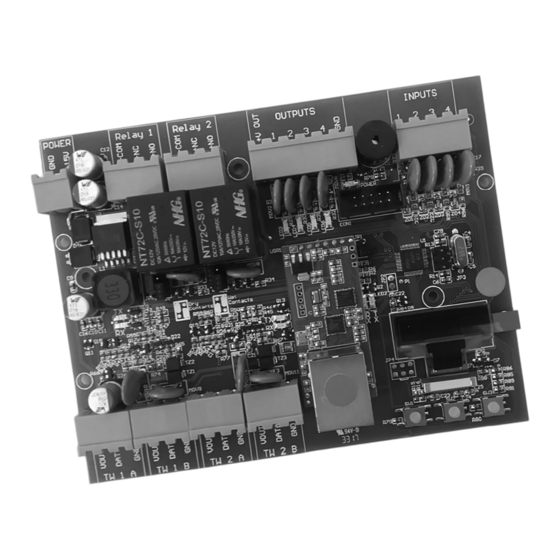
4.4 Node Board Layout Channel 1 Channel 2 Board Relay Relay Digital Digital Power Output Output Output Outputs Ground Inputs Supply Relay Configuration Jumpers OLED Display Taut Wire Sensor Taut Wire Sensor RJ45 Configuration Channel 1 Channel 2 Network Push Buttons Connection... -
Page 9: Connection Examples
4.5 Connection Examples A 4.5.1 Taut Wire Sensors 4.5.2 Digital Outputs... -
Page 10: Digital Inputs
4.5 Connection Examples B 4.5.3 Digital Inputs 4.5.4 Relay Outputs... -
Page 11: Jumper Configuration
4.6 Jumper Configuration The Relay Outputs can be configured to be either a potential free (dry) contact or a wet contact that supplies 12V, by configuring the relevant jumpers, as shown in the figure below. The configuration is also indicated on the board below the jumpers. -
Page 12: Software Setup
5 Software Setup A 5.1 Startup The Taut Wire Node is configured using the OLED display and the left, centre and right pushbuttons below the screen. As soon as power is connected to the unit, the display will briefly show the NEMTEK logo, where after the following default screen is displayed. -
Page 13: Event Log
5 Software Setup B 5.2.5 History Channel 2 • The alarm and error history for all configured sensors on channel 1 are given. Refer to 3.2.4 for further detail. 5.2.6 Event Log • All system events and the time of the event can be viewed. •... - Page 14 5 Software Setup C 5.3.1.2 Count sensors on Channel 1 • All addressed and unaddressed sensors connected to channel 1 will be counted. • Unaddressed sensors under strain (“in alarm”) and addressed sensors (“non 0”) will be shown. These sensors will not be able to be configured with a new address and need to be relieved of any strain and decommissioned before continuing with addressing.
- Page 15 5 Software Setup D 5.3.1.4 Set Channel 1 total sensors • Although the total sensor value is automatically set in 3.3.1.2, it is possible to set it manually. • Press the centre pushbutton to access the sensor amount and use the left and right pushbuttons to increase or decrease the value.
-
Page 16: Channel 2 Installer Menu
This is the address of the Node that will be displayed on the FG7 network controller and Fenceprobe software, and should not be confused with the IP address. For more information, refer to the NEMTEK Network Guide. 5.3.5 Save configuration •... -
Page 17: Appendix A: Error/Alarm Codes
Sensor Left, Service Left and Right Unstable communication to sensor. Check connections and wiring. Sensor Left and Right, Service Left Unstable communication to sensor. and Right Check connections and wiring. *Sensor mounted with NEMTEK logo on top and wire clamp facing towards installer... -
Page 18: Installer Notes
Installer Notes • There are no user serviceable parts on the Node board. • The board should be installed inside a suitable enclosure, away from excessive heat and damp. • Never exceed the maximum ratings given in section 4, as this may lead to permanent damage to the board.
Need help?
Do you have a question about the Taut Wire Node and is the answer not in the manual?
Questions and answers