Table of Contents
Advertisement
Advertisement
Table of Contents

Subscribe to Our Youtube Channel
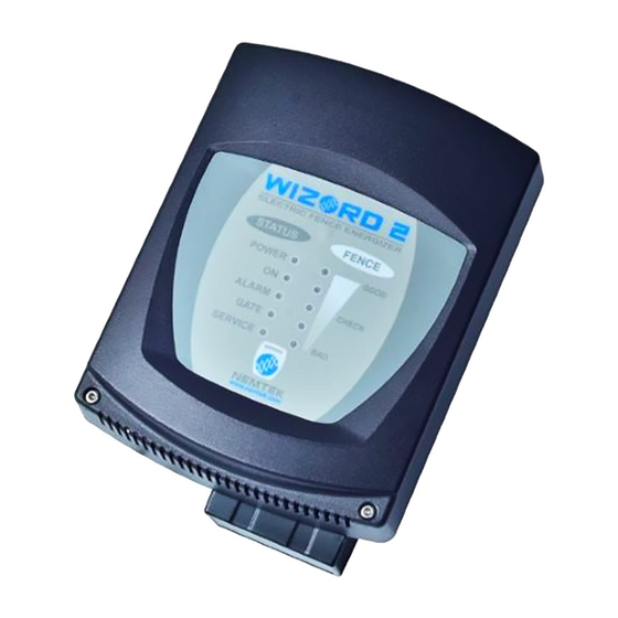
Summary of Contents for Nemtek WIZORD 2
- Page 1 WIZORD 2 Electric Fence Energizer Installer Manual...
-
Page 2: Table Of Contents
Table of Contents Introduction & Disclaimer Nemtek group outlets Mounting & Battery Replacement Connection to the Fence Connections/Configuration Diagram PC Board Replacement Procedures Service Conditions Appendix Installation notes IEC Safety Information Document revision history... -
Page 3: Introduction & Disclaimer
Introduction & Disclaimer INTRODUCTION The WIZORD 2 is a battery (12V 7AH nominal) operated energizer suitable for connection to mains (220-240Vac, 50-60Hz). The batteries to be used are rechargeable lead-acid batteries. Non-rechargeable batteries must not be used. The lead-acid batteries require venting and it is imperative that the energizer be situated in a well-ventilated area. -
Page 4: Nemtek Group Outlets
NEMTEK Group Outlets HEAD OFFICE Tel: +27 (0)11 462 8283 Northriding Commercial Park Fax: +27 (0)11 462 7132 Stand 251, Aintree Street, Northriding Randburg, South Africa EXPORTS Tel: +27 (0)11 462 8283 exports@nemtek.com Fax: +27 (0)11 462 7132 EDENVALE Tel: +27 (0)11 453 1970... -
Page 5: Mounting & Battery Replacement
Mounting & Battery Replacement STEP 1: Disconnect mains. Open the lid after removing the two cap screws. Unplug the battery terminals if connected. STEP 2: Remove screws and battery bracket STEP 3: Remove battery *Dispose of old battery according to legal requirements. -
Page 6: Connection To The Fence
Connection to the Fence OPTION 1: NO EARTH LOOP MONITORING Bridge the earth OUT terminal to earth RETURN terminal. Live wire connection Earth wire connection Earth spikes as per SANS 10222-3 or local specifications OPTION 2: EARTH LOOP MONITORING; GOOD SOIL EARTHING Live wire connection Earth wire connection OPTION 3: EARTH LOOP MONITORING;... -
Page 7: Connections/Configuration Diagram
Connection/Configuration Diagram JUMPER OPERATION: Function Energizer Operation Gate Alarm Switched Input delayed for 4 minutes with energizer On only Gate Alarm Switched Input delayed for 1 minute with energizer On only Panic Alarm Switched Input instantaneous (panic alarm) with energizer On or Off High/Low Switched Input toggles the energizer between Voltage Mode... -
Page 8: Pc Board Replacement Procedures
PC Board Replacement Procedures REMOVAL STEP 1: Disconnect mains power and the battery terminals if connected. STEP 2: Remove screws. STEP 3: Remove all connectors from PC Board. STEP 4: Gently pull PC Board vertically upwards to remove (connections are on the back side of the PC Board). REPLACEMENT STEP 5: Gently push PC Board back into place. -
Page 9: Service Conditions
Service Conditions FUSE DESCRIPTION & FAULT SYMPTOMS SUPPLY BATTERY HOW TO CHECK: (ALL FUSES ARE 2 AMPERE FAST BLOW) SUPPLY: The power LED does not illuminate when the mains power is present AUX: The siren and strobe does not function BATTERY: The energizer switches off in the absence of mains power... -
Page 10: Appendix
Appendix Basic definitions • Electric Fence: A barrier which includes one or more electric conductors, insulated from earth, to which electric pulses are applied by an energizer • Connecting Lead: An electric conductor, used to connect the energizer to the electric fence or the earth electrode •... - Page 11 Appendix (continued) Any part of an electric fence which is installed along a public road or pathway shall be identified at frequent intervals by prominently placed warning signs securely fastened to the fence posts or firmly clamped to the fence wires. The size of the warning signs shall be at least 100mm x 200mm.
- Page 12 Appendix (continued) If connecting leads and electric fence wires are installed near an overhead power line, the clearances shall not be less than those shown in the table below. Power Line Voltage (V) Clearance (m) Equal to or less than 1 000 Greater than 1 000 and equal or less than 33 000 Greater than 33 000 If connecting leads and electric fence wires are installed near an overhead power line, their...
-
Page 13: Installation Notes
Installation Notes • Keep the wires to the fence separate from the keypad, gate, siren, strobe and mains wiring. • Do not try and modify the energizer. Any unauthorized modifications will null and void the warranty and possibly render the unit illegal. •... -
Page 14: Iec Safety Information
IEC Safety Information • There are no user serviceable parts inside the energizer. • If the supply cord is damaged, it must be replaced by the manufacturer, its service agent, or similar qualified persons in order to avoid a hazard. •...


Need help?
Do you have a question about the WIZORD 2 and is the answer not in the manual?
Questions and answers