Advertisement
Installation & Maintenance
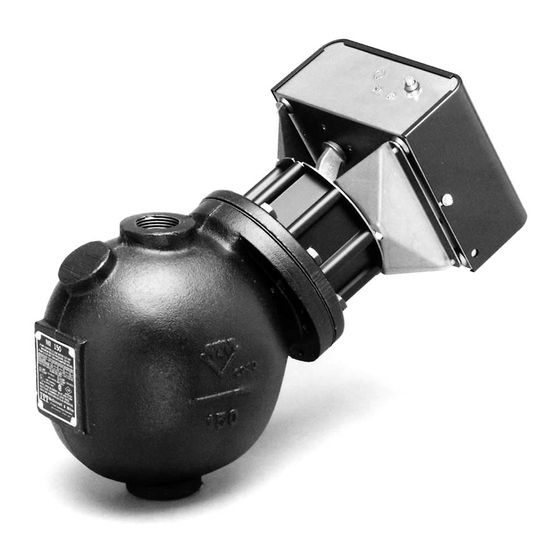
Instructions MM-414
Series 150E and 157E
Low Water Cut-Off/Pump Controllers
For Steam Boilers and Other Level Control Applications
Typical Applications:
– Primary or secondary pump controller/
low water fuel cut-off
for steam boilers
– Motorized valve controller
– Low water and high water cut-off
– Dual pump control
– Alarm actuator
• Before using this product read and understand instructions.
• Save these instructions for future reference.
• All work must be performed by qualified personnel trained in the proper application, instal-
lation, and maintenance of plumbing, steam, and electrical equipment and/or systems in
accordance with all applicable codes and ordinances.
• To prevent serious burns, the boiler must be cooled to 80˚F (27˚C) and the pressure must be
0 psi (0 bar) before servicing.
• To prevent electrical shock, turn off the electrical power before making electrical connections.
• This low water cut-off must be installed in series with all other limit and operating controls
installed on the boiler. After installation, check for proper operation of all of the limit and
operating controls, before leaving the site.
• To prevent serious personal injury from steam blow down, connect a drain pipe to the control
opening to avoid exposure to steam discharge.
• To prevent a fire, do not use this low water cut-off to switch currents over 16A, 1 Hp at
120 VAC or 8A, 1 Hp at 240 VAC, unless a starter or relay is used in conjunction with it.
Failure to follow this warning could cause property damage, personal injury or death.
®
with
MERCURY
FREE
1 HP
Relays
!
WARNING
Series 150E
Series 157E
Advertisement
Table of Contents

Subscribe to Our Youtube Channel
Related Manuals for McDonnell & Miller 150E Series

Summary of Contents for McDonnell & Miller 150E Series
- Page 1 Installation & Maintenance Instructions MM-414 Series 150E and 157E ® Low Water Cut-Off/Pump Controllers For Steam Boilers and Other Level Control Applications with MERCURY Series 150E FREE Typical Applications: 1 HP – Primary or secondary pump controller/ Relays low water fuel cut-off for steam boilers –...
-
Page 2: Specifications
SPECIFICATIONS Maximum Pressure: 150 psi (10.5 kg/cm ELECTRICAL RATINGS & SWITCH RATINGS Supply Probe Full Load (Amps) Locked Rotor (Amps) Pilot Duty (VA) Motor (HP) Voltage Voltage NO (NC), VAC NO (NC), VAC NO (NC), VAC NO (NC), VAC 120 VAC 5 VAC 16 (5.8), 120 96 (34.8), 120... - Page 3 SWITCH SETTINGS: Values are ± ” (6mm). When the water level in the boiler drops below the When the water level in the boiler drops below the middle probe, the circuit is broken which will acti- bottom probe, the circuit is broken which will deacti- vate the pump relay.
-
Page 4: Installation
INSTALLATION – TOOLS NEEDED: IMPORTANT: Follow the boiler manufacturer's Two (2) pipe wrenches, one (1) flatblade screw- instructions along with all applicable codes and driver, and pipe sealing compound. ordinances for piping, blow down valve and water gauge glass requirements. STEP 1 - Determine the Elevation at Which the Low Water Cut-Off/Pump Controller Must be Installed If the control will be the primary low... - Page 5 STEP 2 - Installing the Low Water Cut-Off a. Mount and pipe the low water cut-off (D) on a vertical equalizing pipe (E) at the required ele- vation level, as determined in Step 1. Install blow down valves directly below the lower cross of the water equalizing pipe (F).
- Page 6 Remote Mounting of the Control Box Loosen screws (A) and remove cover. Cover • Disconnect probe wires (red, blue, yellow) from circuit board. Probe Wires • Remove 4 screws (B) connecting control box to brackets, lifting control box from brackets. BCOM BCOM Control Box...
- Page 7 • Remove 6 screws (C) connecting brackets and cover plate to probe housing. Brackets • Remove offset connector from cover plate. Cover Plate Offset Connector Disconnect wires from probes. Probes NOTE Only loosen upper nut to remove probe wire. Upper Nut...
- Page 8 • Mount Control Box in a suitable location near the boiler’s main electrical panel. NOTE Boiler sight glass must be visible from location of Control Box and must be within 25 feet of Control Box. • Install electrical conduit between Probe Housing and Control Box.
- Page 9 Connect wires between Control Box and Probes as follows. Probes Control Top/Blue Top/Blue Blue/Top Middle/Yellow Middle/Yellow Bottom/Red Bottom/Red Yellow/Middle Plate Ground Chassis Ground Red/Bottom Plate Ground NOTE Wire connections at Probes (1/4” Ring Terminal) and Control Panel (22-18 Female Spade) must be made with connectors suitable for high temperature (200˚C) service.
-
Page 10: Step 4 - Electrical Wiring
STEP 4 - Electrical Wiring WARNING • To prevent electrical shock, turn off the electrical power before making electrical connections. • This low water cut-off must be installed in series with all other limit and operating controls installed on the boiler. -
Page 11: Wiring Diagrams
WIRING DIAGRAMS Low Water Cut-Off, Alarm and Pump Up Control • Connect wire “a” from power supply to terminal “H”. FROM BURNER OR ALARM CONTROL CIRCUIT • Connect wire “b” from neutral supply to terminal “N”. BCOM • Connect wire “c” from pump control circuit to terminal “PNO”. TO ALARM CONTROL CIRCUIT •... -
Page 12: Exterior Lights
STEP 5 - Testing IMPORTANT: Follow the boiler manufacturer’s start-up and operating instructions along with all applicable codes and ordinances. Exterior Lights • Green light on: Unit has power • Red light on: Boiler water dropped below the bottom probe for longer than the adjustable time delay setting. - Page 13 The boiler should begin to fill with water. NOTE: If water does not start filling the boiler, immediately turn off the the boiler and make the necessary corrections. For Automatic Reset Models: When the water level reaches the level of the middle probe, the burner circuit should be acti- vated and the Red LED should turn off.
-
Page 14: Troubleshooting
Troubleshooting Green LED does not turn on. Burner does not turn off when water level is • There may be no power to the unit. Check wiring below bottom probe. connected to ‘H’ and ‘N’ terminals on circuit board. • The probes may be fouled with dirt, scale or rust. Verify that the control is being powered when the Remove head assembly to inspect probes. -
Page 15: Maintenance
MAINTENANCE BLOW DOWN PROCEDURE: SCHEDULE: CAUTION Blow down control as follows when boiler is in To prevent serious personal injury from steam operation. pipe blow down, connect a drain pipe to the control opening to avoid exposure to steam • Daily if operating pressure is above 15 psi. discharge. - Page 16 3500 N. Spaulding Avenue Chicago, Illinois 60618 tel: 773 267-1600 fax: 773 267-0991 www.mcdonnellmiller.com ©2002 ITT Industries Inc. Printed in U.S.A. 2-02 210496...
Need help?
Do you have a question about the 150E Series and is the answer not in the manual?
Questions and answers