Table of Contents
Advertisement
Available languages
Available languages
INSTALLATION FOR DRINKING FOUNTAIN
COMBINATION OR RETROFIT
For All KEP( )AC(SL)-EBF-SND/STN Series Combination Drinking Fountains
with Electronic Sports Bottle Filler
This HAND-FREE BOTTLE FILLER RETROFIT is an extension of
the Franke drinking fountains product line that mounts directly
above our Universal Drinking Fountain.
The wall requires a standard 2-outlet electrical receptacle to
accommodate the electrical cords from both the fountain and
the bottle filler. Otherwise, a grounded plug-in outlet adapter
will be required.
If installed onto a refrigerated drinking fountain, chilled water
can be dispensed through the Bottle Filler. Otherwise, room
temperature water will be dispensed.
The Bottle Filler is shipped partially assembled.
If you ordered the Bottle Filler as a combination with a Drink-
ing Fountain, the drinking fountain is plumbed and ready to
attach to the bottle filler.
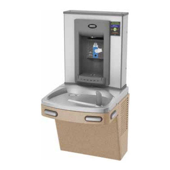
WHEN COMPLETED, THE FINISHED ASSEMBLY WILL LOOK LIKE THIS:
KEP(8)AC-EBF-SND
10/17 | 036865-047
Shown here with the
Sandstone cabinet finish
KEPWEBF
1
Advertisement
Table of Contents

Subscribe to Our Youtube Channel
Related Manuals for Franke KEP AC-EBF-STN Series


Summary of Contents for Franke KEP AC-EBF-STN Series
- Page 1 For All KEP( )AC(SL)-EBF-SND/STN Series Combination Drinking Fountains with Electronic Sports Bottle Filler This HAND-FREE BOTTLE FILLER RETROFIT is an extension of the Franke drinking fountains product line that mounts directly above our Universal Drinking Fountain. The wall requires a standard 2-outlet electrical receptacle to accommodate the electrical cords from both the fountain and the bottle filler.
- Page 2 SECTION 1: GETTING STARTED WHAT’S INCLUDED? TOOLS REQUIRED: 1. Top cap - 3/8" pilot drill and either a step drill bit up to 7/8" 2. 38" of 1/4 OD plastic tubing with 19" of sponge tubing insulation diameter that will drill through stainless steel top or 7/8" 3.
- Page 3 SECTION 2: ROUGH-IN DRAWING Universal Series Drinking Fountain Combination or Retrofit Bottle Filler KEP8AC: 115v GROUNDED NORTH AMERICAN DUPLEX RECEPTACLE REQUIRED. THIS DRINKING WATER COOLER IS INTENDED TO BE CONNECTED TO A 20A MINIMUM GROUND FAULT CIRCUIT INTERRUPTING (GFCI) DEVICE TO MEET UL REQUIREMENTS. 33 3/8 [848] 14 1/8...
- Page 4 SECTION 2: ROUGH-IN DRAWING Universal Series Split Level Drinking Fountain Combination or Retrofit Bottle Filler * On split level models, the Bottle Filler must be mounted on the low unit in order to meet CSA wheelchair guidelines 10/17 | 036865-047...
- Page 5 SECTION 3: INSTALLATION A. DRILLING THE HOLE IN THE TOP FOR WATER LINE CONNECTION SECTION 3: INSTALLATION PRE-DRILLED UNITS: WATER COOLER INSTALLATION INSTRUCTIONS, MODELS: KEPWSBF If your unit was purchased pre-drilled at the factory as a COMBINATION, go to Section 3, Step 5. A.
- Page 6 ALIGN THIS EDGE WITH LEFT EDGE OF COOLER TOP 3 1/4 po [8.3cm] FROM SIDE 2 1/8 po [5.4cm] FROM BACK Mark this center point on the top. Remove the top from the cooler. Then drill a 7/8" [2.2cm] hole through the top at the marked centre point.
- Page 7 SECTION 3: INSTALLATION B. CONNECTING THE WATER LINE If you are retrofitting the bottle filler to an existing cooler, follow the instructions starting on the next page CONNECT THE BOTTLE FILLER TUBE For the single Bottle Filler ready cooler, the tube to connect to the filler is found inside the access panel (the compressor compartment).
- Page 8 SECTION 3: INSTALLATION B. CONNECTING THE WATER LINE (continued) The tee and tube to the Bottle Filler are packaged with the KEPWEBF unit. One branch of the tee will supply the valve on the dummy unit, the other branch of the tee will connect to the Bottle Filler. If a filter is being installed, cut a piece of tubing about 3"...
- Page 9 SECTION 3: INSTALLATION B. CONNECTING THE WATER LINE (continued) To retrofit the Bottle Filler to an existing unit, follow the instructions below. If the cooling tank is non-pressurized, then go to the addendum section, "Pressurizing the cooling tank". Other- wise, proceed to Step 1 below. Non-pressurized units are SINGLE units made since December of 2009. Refer to the schematic below to identify the system you have.
- Page 10 SECTION 3: INSTALLATION B. CONNECTING THE WATER LINE (continued) STEP 2: Disconnect tubing from the elbow on the valve. (Figure 4) STEP 3: Using the 38" piece of tubing provided, cut off 6" and install it on the end of the TEE. Install the remaining tubing onto the branch of the TEE. Connect the other end of the TEE to the tank outlet tubing (tube that was disconnected from the elbow).
- Page 11 SECTION 3: INSTALLATION - Final Steps STEP 5: Feed black and blue tubing up through bushing in top. • For single unit, also feed white tube attached to tee through bushing. • For split level, connect tee a nd white tube packed with bottle filler per schematic below. Attach top to cooler.
- Page 12 SECTION 3: INSTALLATION C. MOUNTING THE FRAME TO THE WALL STEP 1: Place rubber gasket on top of the cooler so it is centered left/right and against the wall. (Figure 11) STEP 2: Set the wall frame onto the gasket. Center it left/right and push it against the wall and mark hole locations for wall fasteners. The gasket will set the frame at the proper height.
- Page 13 SECTION 3: INSTALLATION C: MOUNTING THE FRAME TO THE WALL (continued) STEP 6: Attach Bottle Filler assembly to the frame using the four (4) vandal resistant torx screws. Leave the top cap off until after the program is set for this installation (Figure 15) Figure 15 Torx screws STEP 7:...
- Page 14 BOTTLES SAVED SET-UP GUIDE BOUTEILLES SAUVÉES For ELECTRONIC BOTTLE FILLER FACTORY DEFAULT SETTINGS ARE FOR THE FOLLOWING: • UNFILTERED unit D’accord Service soon Service bientôt • 20 second maximum run time Service Recommended Service recommandé • Units of gallons (when program is set as “FILTERED” unit) Status / Statut You can change program settings by doing a long button press from the home screen showing number of bottles refilled.
- Page 15 ADDENDUM: Pressurizing the cooling tank Unit as it appears with top removed. STEP 1 Unplug un-insulated water line from water valve inlet (JG elbow located left side of water valve facing the front of the cooler). Set tubing aside (being careful to not con- taminate the water contact end of tube).
- Page 16 Addendum: Pressurizing Cooling Tank (continued) STEP 3 Plug un-insulated tubing that was removed in Step 1 into JG elbow leading to the cooling tank from Step 2. STEP 4 Unplug tubing that is onnected to the water valve outlet (JG elbow located on the right side of valve facing the cooler.
- Page 17 Addendum: Pressurizing Cooling Tank (continued) STEP 6 Unplug JG tubing from the cooling tank outlet. Do not set it down. STEP 7 Using tubing removed in Step 6, plug into JG elbow on the right side of the valve. (Be sure to re-route the tubing under existing tubing installed in Step 4 as shown.) STEP 8 Using tubing that is connected to the JG elbow left side of valve...
- Page 18 Cette REMPLISSEUSE DE BOUTEILLES MAINS LIBRES est un pro- longement de la gamme de fontaines à boire Franke qui se monte directement sur notre fontaine à boire universelle. Le branchement des cordons électriques de la fontaine et de la remplisseuse nécessite une prise murale standard double (2 sorties).
- Page 19 SECTION 1 : COMMENT DÉMARRER QU’EST-CE QUI EST COMPRIS? OUTILS NÉCESSAIRES : 1. Couvercle supérieur - 3/8 po foret pilote et soit un peu étape de forage jusqu'à 7/8 po 2. 38 po de tuyau en matière plastique de 1/4 po de D.E. diamètre qui va percer en acier inoxydable haut ou 7/8 po de diamètre et 19 po d’isolant pour tuyauterie en mousse poinçon matrice (version de rénovation seulement)
- Page 20 SECTION 2: DESSIN COTÉ ET DE RACCORDEMENT Combinaison : Fontaines à boire universelles série KEP avec remplisseuse de bouteilles ou pour l'installation sur une unité existante NOTES : 1. SIPHON, ROBINET D’ARRÊT ET PRISE ÉLECTRIQUE NON FOURNIS. 2. PRÉVOIR 4 POUCES [102 MM] AU MINIMUM DE CHAQUE CÔTÉ POUR LA VENTILATION.
- Page 21 SECTION 2: DESSIN COTÉ ET DE RACCORDEMENT Combinaison : Fontaines à boire universelles a deux niveaux série KEP avec remplisseuse de bouteilles ou pour l'installation sur une unité existante * Sur les modèles à deux niveaux , la bouteille de remplissage doit être monté sur l'unité bas afin de répondre se conformer aux directives de la chaise roulante CSA 10/17 | 036865-047...
- Page 22 SECTION 3 : INSTALLATION A : PERÇAGE D'UN TROU DANS LE DESSUS POUR RACCORDEMENT DE L'EAU UNITÉS PERCÉES À L’AVANCE : SECTION 3 : INSTALLATION , passez à la section 3, étape 5. Si votre unité a été achetée percée à l’avance à l’usine comme COMBINAISON DIRECTIVES D’INSTALLATION DU REFROIDISSEUR D’EAU, MODÈLES : KEPWSBF ÉTAPE 1 :...
- Page 23 ALIGNER CETTE LIGNE AVEC LE BORD GAUCHE DU DESSUS DU REFROIDISSUER 3 1/4 po [8.3cm] PARTIR DU CÔTÉ 2 1/8 po [5.4cm] À PARTIR DE L'ARRIÈRE Marquer ce centre sur le dessus. Retirer le dessus du refroidisseur. Percer ensuite un trou de 7/8 po [2.2cm] dans le dessus au point marqué...
- Page 24 SECTION 3 : INSTALLATION B : RACCORDEMENT DE LA CONDUITE D'EAU Si vous installez la remplisseuse de bouteilles sur un refroidisseur existant, suivez les directives sur la page suivante. CONNECTER LE TUYAU SUR LA REMPLISSEUSE DE BOUTEILLES : Dans le cas du refroidisseur simple prêt à recevoir la remplisseuse de bouteilles, le tuyau à raccorder à...
- Page 25 SECTION 3 : INSTALLATION B : RACCORDEMENT DE LA CONDUITE D'EAU (suite) Le té et le tuyau alimentant la remplisseuse de bouteilles sont emballés avec l'unité KEPWEBF. L’un des embranchements du té alimente le robinet sur l’unité sans compresseur, tandis que l’autre embranchement se raccorde à la remplisseuse de bouteilles. En cas d’installation d’un filtre, découper une longueur de tuyau d’environ 3 po afin d’insérer le contacteur débitmétrique juste après le filtre et avant le té.
- Page 26 SECTION 3 : INSTALLATION B : RACCORDEMENT DE LA CONDUITE D'EAU (suite) Pour l’installation de la remplisseuse de bouteilles sur une unité existante, suivre les directives ci-après. Si le réservoir de refroidissement n'est pas sous pression, passer à l'addenda « Pressurisation du réservoir de refroidissement ».
- Page 27 SECTION 3 : INSTALLATION B : RACCORDEMENT DE LA CONDUITE D'EAU (suite) ÉTAPE 2 : Débrancher la tuyauterie du coude sur le robinet. (Figure 4) ÉTAPE 3 : Couper une longueur de 6 po dans le morceau de tuyau de 30 po fourni et les installer sur l’extrémité du TÉ. Installer le reste du tuyau sur l’embranchement du TÉ.
- Page 28 SECTION 3 : INSTALLATION - Étapes finales ÉTAPE 5: Faire passer les tuyaux noir et bleu par la bague dans la partie supérieure. l’unité simple , faire également passer le tuyau blanc fixé au té par la bague. • Dans le cas de l’unité...
- Page 29 SECTION 3 : INSTALLATION C. MONTAGE DU CHÂSSIS SUR LE MUR ÉTAPE 1 : Mettre en place de joint d’étanchéité en caoutchouc sur le dessus du refroidisseur de sorte qu’il soit centré entre la gauche et la droite et contre le mur. (Figure 11) ÉTAPE 2 : Mettre en place le châssis mural sur le joint d’étanchéité.
- Page 30 SECTION 3 : INSTALLATION C. MONTAGE DU CHÂSSIS SUR LE MUR (suite) ÉTAPE 6 : Fixer au châssis la remplisseuse de bouteilles au moyen des quatre (4) vis Torx anti-vandalisme. Laisser le couvercle supérieur ouvert jusqu'à ce que le programme ait été configuré pour cette installation (Figure 15) Figure 15 Vis Torx ÉTAPE 7 :...
- Page 31 BOTTLES SAVED GUIDE DE CONFIGURATION BOUTEILLES SAUVÉES REMPLISSEUSE DE BOUTEILLES - ÉLECTRONIQUE AVEC COMPTEUR DIGITAL Les réglages par défaut en usine sont valables pour: • une unité sans filtre « UNFILTERED » D’accord • une durée maximale de fonctionnement de 20 secondes Service soon Service bientôt Service Recommended...
- Page 32 Addenda : Pressurisation du réservoir de refroidissement Appareil tel qu'il se présente une fois le dessus enlevé ÉTAPE 1 Débrancher la tuyauterie d'eau non isolée de l'entrée du robinet d'eau (coude JG [John Guest] situé à gauche du robinet d'eau orienté vers l'avant du refroidisseur). Mettre la tuyauterie de côté...
- Page 33 Addenda Pressurisation du réservoir de refroidissement (suite) ÉTAPE 3 Rebrancher la tuyauterie d'eau non isolée, que l'on avait retirée à l'étape 1, sur le coude JG menant au réservoir de refroidisse- ment de l'étape 2. ÉTAPE 4 Débrancher la tuyauterie raccordée à la sortie du robinet d'eau (coude JG situé...
- Page 34 Addenda Pressurisation du réservoir de refroidissement (suite) ÉTAPE 6 Débrancher le tuyau JG de la sortie du réservoir de refroidissement. Ne pas le descendre. ÉTAPE 7 Raccorder la tuyauterie retirée à l'étape 6 au coude JG situé à droite du robinet. (Veiller à faire repasser la tuyauterie sous celle existante installée à...
Need help?
Do you have a question about the KEP AC-EBF-STN Series and is the answer not in the manual?
Questions and answers