Table of Contents
Advertisement
Advertisement
Table of Contents

Related Manuals for NRI Currenza H2 Hopper Series

Summary of Contents for NRI Currenza H2 Hopper Series
- Page 1 Technical Documentation Coin payout system hopper Operating instructions 06.08 DVs/UCo/ds Edition 2.5 BA.HOP-EN National Rejectors, Inc. GmbH • Zum Fruchthof 6 • D-21614 Buxtehude Phone: +49 (0)4161-729-0 • Fax: +49 (0)4161-729-115 • E-mail: info@nri.de • Internet: www.nri24.com...
-
Page 3: Table Of Contents
ABLE OF CONTENTS Table of contents General information General information about these instructions Text conventions General information about the hopper currenza h The currenza h features Scope of delivery Models Coin capacity (S/M/L/X) Full and empty recognition Mounting bracket Safety instructions Proper use Protecting yourself and equipment Design... - Page 4 ABLE OF CONTENTS Function Coin reception and pay out Hopper control Control, coin, and error signal (parallel interface only) Control signal to hopper Coin signal to control system Error signal to control system ccTalk data transfer protocol (ccTalk interface only) Anti-jam function Protection against cable break (parallel interface only) Space-saving dual hopper assembly (coin passage)
- Page 5 ABLE OF CONTENTS Technical data Device data Maximum capacity CE Certification Interfaces currenza h with parallel interface – machine Pin assignment Interface description Connection diagram currenza h with ccTalk interface – machine Standard pin assignment using jumpers Alternative pin assignment using jumpers Implemented ccTalk commands Empty/full recognition interface Mounting dimensions...
-
Page 7: General Information
. The first section, however, is designed to help you navigate easily within these operating instructions. General information about these instructions These operating instructions describe the design and operation of the NRI hopper currenza h with parallel or serial ccTalk interface. Chap. 5 and 6 explain the necessary steps for starting up and operating the hopper. -
Page 8: General Information About The Hopper Currenza
If the hopper is to be filled automatically, it can interact with a coin validation system without any problems (e.g. NRI coin validators G-13.mft, G-40 or NRI coin changers c , E-66/A-66, G-46). -
Page 9: Scope Of Delivery
ENERAL INFORMATION Scope of delivery • Hopper currenza h • Mounting bracket Models Most notably the hopper models differ in the coin capacity. All models can be equipped with or without full or empty recognition and be fixed onto two different mounting brackets depending on the machine dimensions. -
Page 10: Mounting Bracket
ENERAL INFORMATION Mounting bracket Depending on the installation options in the machine the hopper is either delivered with a mounting bracket with spigots or with a mounting bracket with large base plate (cp. Chap. 5 "Start- Up"). Fig. 1b: Mounting bracket with large base plate (LH) and spigots (RH) National Rejectors, Inc. -
Page 11: Safety Instructions
This is to ensure you have understood the contents of this manual as well as how to operate the hopper. Proper use The NRI hopper currenza h with parallel/serial ccTalk interface is intended to be used in machines with parallel or serial ccTalk interface and is... -
Page 12: Protecting Yourself And Equipment
Pull out the machine’s mains plug before you install, clean or remove the hopper. Contact NRI if you wish to alter the construction of the device to a greater extent than that described in these instructions. Keep water and other liquids away from the hopper. -
Page 13: Design
ESIGN Design This chapter describes • the main parts the hopper consists of, and • all parts which you need to operate and start up the hopper. Overview of the device (verdeckt) (covered) (verdeckt) (covered) 1 Safety flap 9 Coin outlet 2 Payout disc (covered) 10 Bowl 3 Front bowl cover... -
Page 14: Rotor, Payout Disc, And Safety Flap
ESIGN Bowl and front bowl cover The bowl [2a/10] and bowl cover [2a/3] build the hopper funnel, which collects the coins, in order to feed the rotating disc (Fig. 2b), that pays out the coins. Rotor, payout disc, and safety flap The payout disc (Fig. -
Page 15: Jumpers
ESIGN Jumpers Using the jumpers [2a/14] on the rear of the hopper (accessible by service cover) you can bridge certain pins of the machine interface so that the hopper works no longer in the parallel but in the ccTalk mode or vice versa (see section "Configuring operating mode (parallel/ccTalk)“... -
Page 16: Function
UNCTION Function This chapter describes the functional principle of the hopper: • Coin reception and payout • Hopper control • Anti-jam function • Protection against cable break (parallel interface only) • Space-saving dual hopper assembly (coin passage) • Empty and full recognition (optional) Coin reception and pay out The coins of a particular type are either filled in the hopper bowl before starting up the hopper or continuously sorted into the bowl by an upstream... -
Page 17: Control Signal To Hopper
UNCTION Control signal to hopper If the hopper is in standby mode (after start-up), the machine may activate the hopper motor at any time by transmitting a signal via the control line (voltage drop). The motor turns the payout disc as long as the signal is present. -
Page 18: Cctalk Data Transfer Protocol (Cctalk Interface Only)
UNCTION The red pilot light flashes with every error signal, so that the error is easy to locate and correct (see sections "Pilot lights" in Chap. 3 "Design" and "Troubleshooting" in Chap. 7 "Maintenance and service"). ccTalk data transfer protocol (ccTalk interface only) The control system communicates with the hopper using the serial ccTalk protocol. -
Page 19: Space-Saving Dual Hopper Assembly (Coin Passage)
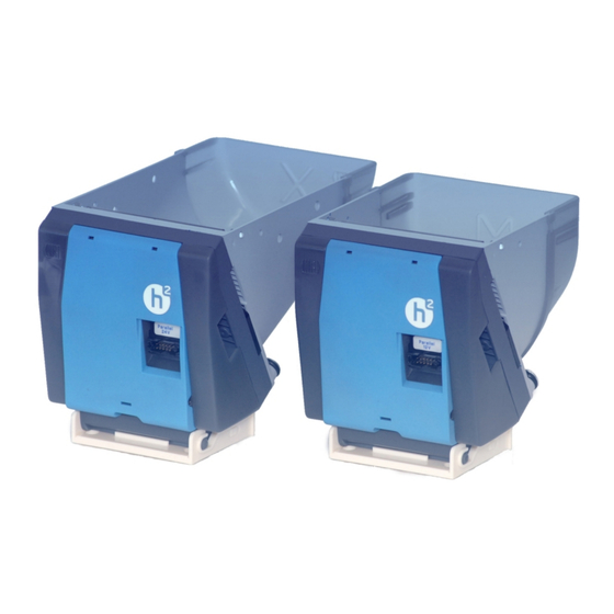
UNCTION Space-saving dual hopper assembly (coin passage) Thanks to the coin passage between the hopper's rear cover and coin payout unit it is possible to install two hoppers in the machine side by side and as close as possible. If the hoppers are mounted accordingly, the coins paid out by the rear hopper can be directed into the return area of the machine through the coin passage of the front hopper. -
Page 20: Full Recognition
UNCTION Full recognition The hopper uses the full recognition to signal the control system that no more coins can be fed into the hopper, so that it does not overflow. The filling quantity is also monitored by electric contacts in the hopper bowl or or bowl cover (connot be retrofitted): If the filling level is below the contacts, no current flows. -
Page 21: Start-Up
TART Start-up This chapter describes how to • start up the hopper in a machine • align tow hoppers with coin passage For all installation work on the hopper or the machine please observe the following safety instructions: The hopper may only be connected by a qualified electrician. The hopper is not suited for outdoor use. -
Page 22: Installing Mounting Bracket
TART Installing mounting bracket The hopper is installed in the machine using the mounting bracket. Installation differs depending on the mounting bracket. Installing mounting bracket with spigots Install the mounting bracket in the machine in consideration of the both underside spigots [5a/1] using four fixing screws and the boreholes [5a/ 2] (Ø... -
Page 23: Aligning Two Hoppers With Coin Passage
If you do not want the hopper to operate in the mode ordered by you and set by NRI and want to reconfigure the machine interface or set a particular ccTalk address (defaul setting: 3), it is advisable to change these settings before connecting and installing the hopper (see Chap. -
Page 24: Connecting Hopper
6.35 x 0.80 each). If the hopper is equipped with an empty or full recognition only, the contact has already been connected to the hopper PCB by NRI and the empty/full signal is Fig. 7b: Connectors for empty/full recognition transmitted via the 10-pole machine interface. -
Page 25: Mounting And Filling Hopper
TART Mounting and filling hopper Slightly tilt the hopper at the rear and use its two mounting studs [8a/1] to slide the hopper in the rear guides [8a/2] of the mounting bracket. Press the hopper into the mounting bracket, so that it engages behind the ejector Fig. -
Page 26: Operation
PERATION Operation This chapter describes the operation, i.e. the setting of specific functions on the hopper itself: • Configuring operating mode (parallel/ccTalk) • Selecting ccTalk hopper address • Removing hopper Configuring operating mode (parallel/ccTalk) In order to change the operating mode (default setting: customized): Tools: Slotted screw driver, tweezers Detach hopper from mounting bracket (see section "Removing hopper"... -
Page 27: Jumper Positions For Parallel Mode
PERATION Jumper positions for parallel mode Connector Pin [9b/3] Jumper positions for ccTalk mode Standard contacting: Connector Pin [9b/3] Alternative contacting for ccTalk data line: Connector Pin [9b/3] U++ = Power supply = Pulse out = Error out = Full out = Empty out M12 = 12V motor (cp. -
Page 28: Selecting Cctalk Hopper Address
PERATION Selecting ccTalk hopper address To alter the ccTalk hopper address (default setting: 3): Tools: Slotted scew driver, pointed object Detach hopper from mounting bracket (see section "Removing hopper" in this chapter). Remove service cover (detach from the bottom using a slotted screw driver, see Fig. -
Page 29: Removing Hopper
PERATION Removing hopper It is very easy to remove the hopper from the mounting bracket: Press the ejector lever [11/1] down as far as its lips release the hopper A. Lift the hopper front B and disengage the hopper from the guides [11/2] of the mounting bracket C. -
Page 30: Maintenance And Service
AINTENANCE AND SERVICE Maintenance and service In this chapter you will find out how to • clean the hopper, and • remedy the cause of a malfunction. Please pull out the machine’s mains plug before you clean or maintain the hopper. Cleaning hopper (every six month) The coins may leave residues on sensitive parts of the payout unit, when they are transported. - Page 31 AINTENANCE AND SERVICE Clean payout disc [12b/3] and all other parts, that are contaminated by the coins, with a cloth/brush. Under no circumstances may the cloth be so wet that fluid runs into the device. Other the hopper will be damaged.
-
Page 32: Troubleshooting
AINTENANCE AND SERVICE Troubleshooting Malfunctions can occur in all electromechanic devices. These do not always have to be faults in the device. In many cases the reason is improper connections or incorrect settings. Therefore: please first of all check, whether the malfunction can simply be remedied using the following table. Problem Possible causes Remedy, hints... - Page 33 AINTENANCE AND SERVICE Problem Possible causes Remedy, hints Red LED flashing Coin outlet blocked 7x (slow • Eliminate blockade payout) • Check outlet area • Check/replace ejector assembly (service case) Error, hopper • Connect hopper to control system connection (parallel correctly interface only) •...
-
Page 34: Technical Data
ECHNICAL DATA Technical data This chapter contains information about • all relevant hopper data • maximum capacities • the CE certification • the machine and empty/full interfaces • mounting dimensions Device data Supply voltage 12/24V DC, ± 10 % Current consumption Standby mode: approx. -
Page 35: Maximum Capacity
ECHNICAL DATA Coin payout Coin diameter: 18.5–25.8mm Coin thickness: 2.0–2.6mm (optional 2.6–3.3) Speed: 7.5 coins/sec. max. Diameter (mm) ○ ○ ○ ○ ○ ○ ○ ○ ○ ○ ○ ○ ○ ○ ○ ○ ○ ○ ○ ○ ○ ○ ○... -
Page 36: Ce Certification
ECHNICAL DATA CE Certification The CE certificate (CE = Communautés Européennes) confirms that our products comply with specified basic requirements of the applicable directive. The CE certificate is not a quality assurance certificate in terms of the quality expected by the manufacturer but only in terms of the quality demanded legally. -
Page 37: Interfaces
ECHNICAL DATA Interfaces On the following pages you will find information for connecting the hopper to the machine: • Pin assignment of machine and empty/full recognition interface • Machine interface description • Connection diagram • Implemented ccTalk commands currenza h with parallel interface –... -
Page 38: Connection Diagram
ECHNICAL DATA Connection diagram Error signal Coin signal Control signal Fig. 13: Connection diagram for parallel hopper National Rejectors, Inc. GmbH, Buxtehude... -
Page 39: Currenza H 2 With Cctalk Interface - Machine
ECHNICAL DATA currenza h with ccTalk interface – machine Standard pin assignment using jumpers Pin no. Function ccTalk data V DC V DC V DC n.c. V DC Alternative pin assignment using jumpers Pin no. Function V DC V DC V DC ccTalk data n.c. -
Page 40: Implemented Cctalk Commands
ECHNICAL DATA Implemented ccTalk commands Command Function Simple poll Request manufacturer ID Request ID Request product code Request serial number Request software version Read opto states Enter new PIN number Enter PIN number Request payout high/low status Request build code Emergency stop Request address mode Request hopper dispense count... -
Page 41: Mounting Dimensions
ECHNICAL DATA Mounting dimensions View from the side Top view National Rejectors, Inc. GmbH, Buxtehude... -
Page 42: View From The Side
ECHNICAL DATA View from the side Top view National Rejectors, Inc. GmbH, Buxtehude... -
Page 43: View From The Side
ECHNICAL DATA View from the side Top view National Rejectors, Inc. GmbH, Buxtehude... -
Page 44: Index
NDEX Index Commands, ccTalk hopper 40 Components 13 Accentuation in the text 7 Condensation 34 Address, ccTalk hopper 28 Conformity declaration 36 Adjustment 26 Connection 21 Advantages 8 diagram, hopper with parallel interface 38 Angle, mounting position 35 empty/full contacts 24, 40 Anti-jam function 18 hopper 24 Appliance, proper 11... - Page 45 NDEX Ejector lever 12 Input line 16, 37 Electric strength 34 Inrush current 34 Electrostatic discharge 12 Installation 21 EMC directive 36 hopper 24, 25 Empty/full recognition 12 mounting bracket 22 interface 12, 40 two hoppers 23 pin assignment 40 Interface 12, 14, 15, 34, 37 signal line 37 configure 26...
- Page 46 NDEX Notes 7 S hopper 9 Safety flap 12, 14 instructions 7, 11 Operating Scope of delivery 9 mode, configure 26 Sensor, clean 30 voltage 34 Service 30 Operation 26 cover 12 Output line 17, 18, 37 Settings 26 Signal lines 37 Speed, coin payout 35 Parallel operation, configure 26 Start-up 21...
-
Page 47: Glossary
LOSSARY Glossary ccTalk Serial communication protocol developed by Money Controls (formerly Coin Controls) to provide secure transfer of credit and status information between devices used in the automated money transaction business, such as hoppers, coin validators, coin changers or bill validators (www. ccTalk.org). Coin payout sensor The coin payout sensor is positioned in front of the hopper's coin outlet and monitors the payout of a coin.
Need help?
Do you have a question about the Currenza H2 Hopper Series and is the answer not in the manual?
Questions and answers