Table of Contents
Advertisement
Advertisement
Table of Contents
Troubleshooting

Summary of Contents for TissueLink Aquamantys System
- Page 1 SERVICE MANUAL...
- Page 2 _______________________________________________________________________________ SERVICE MANUAL Software Version 1.10...
- Page 3 Pump Generator Users Guide and in the Instructions for Use which accompany individual Aquamantys Disposable Bipolar Devices which are designed to be used as a part of the Aquamantys System. Federal (USA) Law restricts this device to sale, distribution or use by or on Precaution: the order of a physician.
-
Page 4: Table Of Contents
_______________________________________________________________________________ Table of Contents Foreword .......................iii Table of Contents ....................iv List of Tables and Figures..................v Section 1 - Introduction ................... 1-1 General Description ....................1-1 RF Power ......................1-1 Simultaneous RF Power and Saline Delivery............. 1-1 Saline Flow Rate Setting ..................1-1 Priming ....................... -
Page 5: List Of Tables And Figures
_______________________________________________________________________________ List of Tables and Figures Figure 2-1. Front Panel .................... 2-1 Figure 2-2. Rear Panel ..................... 2-1 Figure 3-1. Output Voltage vs. Power Setting ............. 3-6 Figure 3-2. Output Power vs. Resistance..............3-6 Figure 3-3. Saline Flow Rate vs. Power Setting ............3-7 Figure 3-4. -
Page 6: Section 1 - Introduction
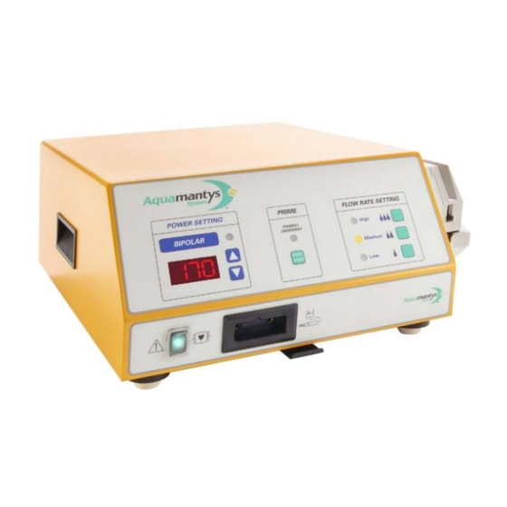
_______________________________________________________________________________ Section 1 - Introduction General Description The Aquamantys™ Bipolar Pump Generator is an electrosurgical generator with a rotary peristaltic pump which is for use only with Aquamantys single-use disposable bipolar devices for concurrent delivery of radio-frequency energy with saline for hemostatic sealing of blood vessels in soft tissue and bone. -
Page 7: Section 2 - Controls, Indicators, And Receptacles
_______________________________________________________________________________ Section 2 - Controls, Indicators, and Receptacles This section contains information about the front and rear panels, including all controls, indicators, receptacles, and the fuse drawer. Figure 2-1. Front Panel Figure 2-2. Rear Panel... - Page 8 _______________________________________________________________________________ Power On/Off Switch The main power On/Off switch is located at the bottom left corner of the front panel on the Aquamantys Pump Generator. The unit is switched on by pressing the top portion of the switch marked “⏐”. The switch will be illuminated green when it is on.
- Page 9 _______________________________________________________________________________ Flow Rate Setting Buttons These buttons control the saline flow rate. Pressing one of these three buttons selects the flow rate setting of either MEDIUM or HIGH for each respective power setting. The MEDIUM flow rate setting is automatically selected as the default setting if no setting is manually selected.
- Page 10 _______________________________________________________________________________ 14 Name Plate This plate specifies the model number, serial number, nominal line voltages, frequency, current and fuse rating information of the Aquamantys Pump Generator. 15 Fuse Drawer This fuse drawer contains two fuses. The Aquamantys Pump Generator Service Manual contains information for changing fuses.
-
Page 11: Symbols
_______________________________________________________________________________ Symbols Several symbols appear on the Aquamantys Pump Generator front panel, rear panel, and pump head. Symbol Indicates Symbol Indicates This equipment intentionally supplies ATTENTION – Consult non-ionizing RF energy for physiologic accompanying documents effect Volume control of RF power Defibrillation-Proof activation tone. -
Page 12: Section 3 - Technical Specifications
_______________________________________________________________________________ Section 3 - Technical Specifications Performance Characteristics General Output Configuration Isolated output Cooling Internal fan, natural convection on outside of chassis Three (3) digital seven-segment displays: Display 0.55 inches (1.4 cm) each Dimensions and Weight 12.2 inches (31.0 cm) Width Depth 15.2 inches (38.5 cm) -
Page 13: Electromagnetic Compatibility
_______________________________________________________________________________ Activation Tone Frequency (nominal) 940 Hz Alarm Tone Frequency (nominal) 349, 415, 524, 698 Hz Leakage Currents See IEC test record Electromagnetic Compatibility The Aquamantys Pump Generator is intended for use in the electromagnetic environment specified below. The customer or user of the unit should assure that it is used in such an environment. - Page 14 _______________________________________________________________________________ Nominal Minimum Maximum Max Current Fuse Type of fuse Rating 5x20mm, 4.00 T5.0A Glass fine fuse 5x20mm, 3.50 T4.0A Glass fine fuse 5x20mm, 1.85 T2.0A Glass fine fuse Mains line frequency (nominal): 50/60 Hz Maximum power consumption: 420 VA Mains cable: 3-conductor hospital grade...
-
Page 15: Standards And Iec Classifications
_______________________________________________________________________________ Standards and IEC Classifications ATTENTION Consult accompanying documents. To reduce the risk of electric shock, do not remove the cover. Refer servicing to qualified service personnel. DANGER Explosion risk if used with flammable anesthetics. Class I Equipment Accessible conductive parts cannot become live in the event of a basic insulation failure because of the way in which they are connected to the protective earth conductor. -
Page 16: Output Characteristics
_______________________________________________________________________________ Output Characteristics Maximum Pump Generator Outp Mode Maximum Maximum Short Maximum Crest Factor Open Circuit Circuit Current Power Voltage Setting Watts Bipolar 650 (325) RF Output Output Power 20 to 200 watts Adjustable Power 5 watts, from 20 to 100 watts Increments 10 watts, from 100 to 200 watts 50 to 110 ohms... -
Page 17: Figure 3-1. Output Voltage Vs. Power Setting
_______________________________________________________________________________ Figure 3-1. Output Voltage vs. Power Setting Bipolar Vpk Bipolar Vrms Power Setting (Watts) Figure 3-2. Output Power vs. Resistance Bipolar Pow er @ 200 Watt Setting Bipolar Pow er @100 Watt Setting 900 1000 Load (Ohms) -
Page 18: Figure 3-3. Saline Flow Rate Vs. Power Setting
_______________________________________________________________________________ Figure 3-3. Saline Flow Rate vs. Power Setting High Medium Power Setting (Watts) Figure 3-4. Power Setting Characteristics at rated load Power Setting (watts) -
Page 19: Accessories
Max Current Fuse Type of fuse Rating 5x20mm, Glass 4.00 T5.0A fine fuse 5x20mm, Glass 3.50 T4.0A fine fuse 5x20mm, Glass 1.85 T2.0A fine fuse For a listing of additional Aquamantys System accessories please refer to the TissueLink Medical Product Catalog. -
Page 20: Section 4 - Circuitry Description
_______________________________________________________________________________ Section 4 - Circuitry Description Overview The Aquamantys Pump Generator is comprised of the following components: • Power supply unit with mains transformer, power supply PCB (Supply_TL1) with rectifiers, filter capacitors and an inrush current limitation circuit. • RF generator PCB (RFGEN_TL1). This PCB comprises the entire internal voltage processing circuit, the RF generator, the motor controller for the peristaltic pump, 2 microcontrollers for sequence control and monitoring the entire process. -
Page 21: Description Of Unit Components
_______________________________________________________________________________ Description of unit components Primary power supply Mains voltage reaches the power supply PCB via a line filter socket and an illuminated power switch. The mains transformer connects to this PCB. The mains voltage reaches the mains transformer’s split primary winding via an inrush current limitation circuit and a voltage selector (115 V/230 V). - Page 22 _______________________________________________________________________________ The power supply PCB (Supply_TL1) and the mains transformer comprise the power supply unit, which is mounted on an aluminum plate. This power supply unit is fastened in the housing with 4 screws. The mains voltage reaches the Supply_TL1 circuit input (mains socket, J1) via the line filter socket and the power switch.
-
Page 23: Figure 4-2. Power Supply Block Diagram
_______________________________________________________________________________ • LED4: POWER-GOOD. Note: The LEDs protrude over the PCB edge and can be seen after removal of the floor panel. The output socket pin assignment is as follows (starting from fuse FU3): • PIN1 – 2: + / - 160 V, filtered, unregulated •... - Page 24 _______________________________________________________________________________ RF Generator Circuit Board (RFGEN_TL1). The RF generator PCB comprises all components of an RF device and also the voltage regulator for the pump motor. Power is fed in via the “from power supply” input on the power supply PCB (Supply_TL1). Fixed voltage regulators reduce the supplied low voltages (+/- 25V) to +5 V (for the microcontrollers and the display) and +/-15 V for the small signal components.
-
Page 25: Figure 4-3. Rf Generator Block Diagram
_______________________________________________________________________________ DOWN Aplicator U1_Voltage Output Hf1 / Hf2 RFB0 / RFB1 RF_Generator Regulator T ransform er, Power_Monitor and Filter 0 to 100V Safety_Caps S a fety_T rigge r Circ uit U1_S E T / U1_VAL Switch_Monitor (ST C) Fixed voltages + 5V , + 15V -15V I2C-Bus... -
Page 26: Figure 4-4. Display Board Block Diagram
_______________________________________________________________________________ The display circuit board (TL_PM) The display (TL_PM PCB) is connected to the RF generator PCB. Power supply (+5 V) and communication (I²C bus) occur directly from the RF generator PCB. Figure 4-4. Display Board Block Diagram... -
Page 27: Section 5 - Testing And Servicing Safety
Shock Hazards: All servicing should be referred to qualified service personnel. It is recommended that you contact the TissueLink Medical Customer Service Department to have the Aquamantys Pump Generator serviced. Potentially lethal voltages are present within the unit when energized. Use extreme caution if the bottom panel is removed for maintenance or attempted repair. -
Page 28: Section 6 - Maintenance And Repair
_______________________________________________________________________________ Section 6 - Maintenance and Repair Responsibility of the Manufacturer TissueLink Medical is responsible for the safety, reliability, and performance of the Aquamantys Pump Generator only under the following circumstances: • Installation and setup procedures in this manual are followed. -
Page 29: Table 6-1. Leakage Current And Pe Conductor Limits
_______________________________________________________________________________ Perform leakage and PE conductor tests per the safety tester instructions. The following limits must be complied with in accordance with IEC60601 (Class I, Type CF device): Table 6-1. Leakage Current and PE Conductor Limits Measured Characteristic Maximum Value PE conductor impedance 0.2 Ω... - Page 30 _______________________________________________________________________________ RF Output Power Accuracy Verification Warnings: Load resistors used to test the output of the Aquamantys Pump Generator will become extremely hot. Use extreme caution to avoid any contact. All load resistors must be properly mounted and isolated from any flammable materials.
-
Page 31: Figure 6-3. Adjusting The Flow Rate Setting
_______________________________________________________________________________ Peristaltic pump test (function, flow rate accuracy) Warnings: Always close the pump head prior to activating pump motor. Always allow the pump head rotor to come to a complete stop prior to opening the pump head. Prevent fingers or loose clothing from being caught in pump head rotors. -
Page 32: Table 6-2. Flow Rate Vs Pump Shaft Revolutions Limits
_______________________________________________________________________________ Verifying Proper Pump Head Rotation Rate • If it is open, close the pump head by moving and locking the pump lever down toward the rear of the pump generator. • Remove the black rubber plug on the pump face which covers the pump shaft. -
Page 33: Figure 6-4. Initiating The Priming Sequence
Replace the power cord with an appropriate hospital grade replacement if any of these conditions or other evidence of damage exists. Replacement power cords may be ordered from TissueLink Medical Customer Service by calling 866.777.9400 (+1.603.742.1515 outside U.S.). -
Page 34: Returning The Aquamantys™ Pump Generator For Service
Before returning the unit to TissueLink Medical, call TissueLink Medical Customer Service for assistance. If you are instructed to send the unit to TissueLink Medical, first obtain a Return Goods Authorization Number and then ship the unit to TissueLink Medical for service. - Page 35 Pump Generator from damage. Contact TissueLink Medical for a shipping carton if you do not have comparable packaging. Ship the unit to TissueLink Medical, Inc., One Washington Center, Suite 400, Dover, NH, 03820 USA.
-
Page 36: Section 7 - Troubleshooting
_______________________________________________________________________________ Section 7 - Troubleshooting This section contains information about: • General Troubleshooting Guidelines • Troubleshooting Malfunctions • Responding to Alarms General Troubleshooting Guidelines If the Aquamantys Pump Generator malfunctions, first check for obvious conditions that may have caused the problem: •... -
Page 37: Troubleshooting Malfunctions
Solution No power No power cord Use power cord shipped with Aquamantys Pump Generator or contact TissueLink Medical Customer Service to obtain new power cord. Wrong power cord utilized Use power cord shipped with Aquamantys Pump Generator or contact TissueLink Medical Customer Service to obtain new power cord. - Page 38 Aquamantys disposable bipolar device pump is Guide slots on pump head housing may be out jammed by pump segment connector which of adjustment. Contact TissueLink Medical. has inadvertently entered into pump head. Use a backup unit or traditional hemostatic techniques to complete the surgical procedure.
- Page 39 Generator doesn’t Pump Generator damaged Contact Biomedical Engineering Department or work a TissueLink representative for assistance. Use a backup Pump Generator or traditional hemostatic techniques to complete the surgical procedure if repairs cannot be made prior to the scheduled surgical procedure.
- Page 40 Wrong fluid used for device irrigation Only utilize 0.9% sodium chloride solution with the Aquamantys System Tip(s) of Aquamantys disposable bipolar Clean device tips with gauze. Ensure device clogged by tissue or coagulated blood precautions are taken to avoid inadvertent device activation when cleaning device tips.
-
Page 41: Responding To Alarms
_______________________________________________________________________________ Responding to Alarms When the Aquamantys Pump Generator senses a malfunction, a sequence of alarm tones will sound and the RF power is disabled. Additionally, the RF Power Indicator will show “Err” and blink alternately with a special error code number(s). 1. -
Page 42: Section 8 - Error Codes And Error Handling
_______________________________________________________________________________ Section 8 - Error Codes and Error Handling The Aquamantys Pump Generator self-test, which is executed immediately following power up, comprises several phases. The first phase covers the internal RAM and the MPU0 watchdog test. The second phase tests the major computer hardware components (microcontroller). -
Page 43: Table 8-2. Error Code Descriptions
_______________________________________________________________________________ Table 8-2. Error Code Descriptions Recommended Troubleshooting Sequence Checked During RFGen Power Display Test Error No. Brief description Use? Supply Resistor Remarks CRC check error RAM test error CRC check error Watchdog error Local I²C BUS errors (EEPROM) Controller I²C BUS error µController defective Software inconsistency Heat sink MP1... -
Page 44: Mpu1 Error Codes
_______________________________________________________________________________ Error Code Notes: 1) Check (listen) for proper blower operation. Ensure that the recommended duty cycle (40 secs on/80 secs off) is observed. 2) Error code 023 (MPU1 error) has it’s own subset of error conditions. See MPU1 Error section below. 3) Check proper functioning of pump motor. -
Page 45: Table 8-4. Mpu1 Error Code Description
_______________________________________________________________________________ Table 8-4. MPU1 Error Code Description Checked Recommended Troubleshooting During Sequence Use? RF Gen Power Display Test Error No. Brief Description Supply Resistor CRC check error 023 / 001 RAM test error 023 / 002 CRC check error 023 / 003 Watchdog error 023 / 004 Local I²C BUS errors (EEPROM) -
Page 46: Section 9 - Service Access
_______________________________________________________________________________ Section 9 - Service Access The Aquamantys Pump Generator should only be serviced by a qualified technician. Removal of the bottom cover voids any warranty. Opening the unit To open, turn the unit upside down and remove the floor panel. To do so, remove the screws with a Philips screwdriver and take off the floor panel. -
Page 47: Removing The Power Supply Unit
_______________________________________________________________________________ Removing the power supply unit The power supply PCB and the mains transformer – the power supply unit – are mounted on an aluminum plate. After removal of 4 Philips screws the entire power supply unit can be lifted and deposited next to the unit. -
Page 48: Removing The Cooler Fan Unit
_______________________________________________________________________________ Removing the RF generator PCB (RFGEN_TL1) First remove the rear panel and unplug all connectors. 7 nuts hold the RF generator PCB in the housing. Unscrew them, remove the washers and the two serrated washers and carefully lift the PCB out. Make sure during installation (replacement) of the RF generator PCB that the serrated washers are installed in the same positions (bores with copper ring in the PCB) as these serve for equipotential bonding... -
Page 49: Section 10 - Schematic Diagrams
_______________________________________________________________________________ Section 10 - Schematic Diagrams Figure 10-1. Supply_TL1 10-1... - Page 50 _______________________________________________________________________________ Figure 10-2. Power Supply: Voltage Regulators, Output Stages 10-2...
- Page 51 _______________________________________________________________________________ Figure 10-3. Power Supply: U1 and U2 Voltage Regulators and Current Limiters 10-3...
- Page 52 _______________________________________________________________________________ Figure 10-4. Power Supply: Safety Circuits and Analog Conversion 10-4...
- Page 53 _______________________________________________________________________________ Figure 10-5. RF Generator: Output Stage, Output Filter Overload Protection 10-5...
- Page 54 _______________________________________________________________________________ Figure 10-6. RF Generator: RF and Pulse Oscillator, Analog Interface 10-6...
- Page 55 _______________________________________________________________________________ Figure 10-7. RF Generator: Power and Current Limiters 10-7...
- Page 56 _______________________________________________________________________________ Figure 10-8. MPU0: Power Supply, RF Generator Control 10-8...
- Page 57 _______________________________________________________________________________ Figure 10-9. MPU1: RF Output Control, System Monitoring 10-9...
- Page 58 _______________________________________________________________________________ Figure 10-10. System Monitoring: RF Power Measuring 10-10...
- Page 59 _______________________________________________________________________________ Figure 10-11. System Monitoring: Hand Switch Recog., Analog Control 10-11...
- Page 60 _______________________________________________________________________________ Figure 10-12. System Monitoring: Hand Switch Test Xfmr 10-12...
- Page 61 _______________________________________________________________________________ Figure 10-13. Output Control: RF Output, Power Sense Xfmrs 10-13...
- Page 62 _______________________________________________________________________________ Figure 10-14. Sound Output, Master Memory, Clock, I²C 10-14...
- Page 63 _______________________________________________________________________________ Figure 10-15. Display Board 10-15...
-
Page 64: Section 11 - Warranty
Section 11 - Warranty LIMITED EXPRESS WARRANTY For one (1) year from the date of shipment from TissueLink, if an Aquamantys Pump Generator or Cart is found, to TissueLink’s satisfaction, to be inoperable during normal and proper use in accordance with applicable instructions, TissueLink Medical, Inc. - Page 65 +1.603.742.1488 (outside the U.S.) E-mail: customerservice@tissuelink.com © Copyright 2005 TissueLink Medical, Inc. All rights reserved. Printed in USA. TISSUELINK, the TISSUELINK LOGO, SIMPLY BETTER SURGERY, AQUAMANTYS and the AQUAMANTYS LOGO are trademarks of TissueLink Medical, Inc. Additional trademarks are the property of their respective owners.