
Summary of Contents for Fox Electronics FX255 D3
- Page 1 ELECTRONICS (PTY) LTD SPECIALIZED SECURITY MONITORING EQUIPMENT FX 255 D3 INSTRUCTION MANUAL V1.0...
-
Page 2: Table Of Contents
PLEASE READ THIS MANUAL CAREFULLY TO ENSURE THE CORRECT OPERATION AND INSTALLATION OF THE DECODER. CONTENTS Safety precautions - - - - - - - - - - - - - - - - - - - - - - - - - - - - - - - - - Introduction &... -
Page 3: Safety Precautions
Do not close any of the ventilation holes on the lid. POWER REQUIREMENTS: 220v AC 50Hz 13.8V DC external adaptor To keep the warranty void the FX255 base station may only be repaired by an Fox electronics authorized repair technician. Any unauthorised repairs can cause poor performance of your equipment. - Page 4 INTRODUCTION The FX 255 D3 alarm monitoring station is a compact self-contained unit designed for monitoring of long range data transmitters as a standalone unit or with a repeater network. It consists of a decoder/encoder, receiver, transmitter, internal power supply and backup battery in a compact durable enclosure, and is programmable to be used as a decoder or repeater station.
-
Page 5: Specifications
SPECIFICATIONS General Frequency range 135 - 175 MHz Frequency control Synthesized Frequency stability 5 ppm Channel spacing 12.5 KHz Operating temperature range -10 to + 60°C Termination SO239 Impedance 50 Ohms Dimensions W 250mm x D 220mm x H 75 mm Receiver Sensitivity -120 dBm (12 dB Sinad EIA) -
Page 6: Installation
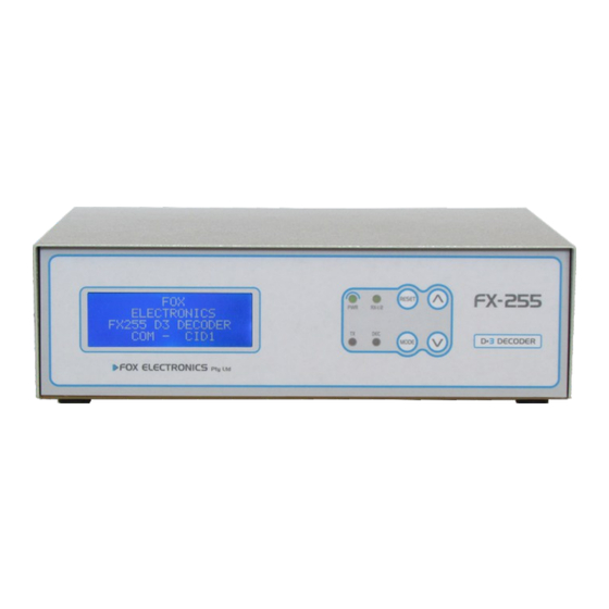
2. Insert and tighten the antenna connector. RS232 3.Connect the USB (or RS232) cable connector to the FX255 D3 Base and to an available computer USB (or RS232) port. USB driver software must be loaded onto the windows based software. Note Windows XP and older is not supported. - Page 7 Fx255 CONTROL LAYOUT 1. Status LED : Indicates microprocessor operation 2. Reset Switch : Used to reset or return out of a display function. 3. Volume UP : Increase the speaker volume. 4. Volume DOWN : Decrease the speaker volume. 5.
-
Page 8: Operation
AC loss. RX1/2 - LED indicates Green when RX1 is selected and Red for RX2. TX - LED indicates when the FX255 D3 is transmitting data. DEC - LED will flash every time data is read off the network. Buzzer Reset and Code Acknowledge After a code is received the buzzer will auto reset or if programmed it will stay on until the reset button is pressed. - Page 9 Remote Reset and External Buzzer Connection RESET N/O EXTERNAL CONTACT 12V BUZZER Remote Reset : Used for external reset switch / remote connection A normally open contact is required for reset. External Buzzer : Output at 12 volt and 1 ampere maximum load. Note polarity on terminal block.
-
Page 10: Programming
PROGRAMMING Insert the FX Programmer into the programming socket located at the back of the FX 255 D3 decoder. The programmer will power up and you are ready to start programming. SETTING UP GENERAL FEATURES Press [1] to view the settings of general features. To enable a feature the corresponding NUMBER must be ON. - Page 11 TIME AND DATE PROGRAMMING The FX255 is equipped with a real time clock and calendar that will NOT be lost if the unit is turned off. To program the time and date follow these instructions: PRESS [6][1234][6][1] - The current date and time will be displayed. Enter new [HOUR] [MIN] [DAY] [MONTH] [YEAR] [#] to save To set the time to 16:30 and the date to 24/03/2016 the entry's will be: PRESS [16] [30] [24] [03] [16] >followed by a long BEEP .
- Page 12 USB- The use of the USB port requires Driver software to be installed on the monitoring computer. The software drivers are supplied with the FX255 D3. DATA MESSAGE COMPOSITION Enter [1] [3] [#] on the LCD programmer to enable the standard format.
- Page 13 RS 232 CABLE CONNECTION TO A COMPUTER. BASE COMPUTER DB 9 FEMALE DB 9 FEMALE DB 25 FEMALE Pin 2 - Data Rx ------------ Pin 3 - Data Tx Pin 2 - Data Tx Pin 3 - Data Tx ------------ Pin 2 - Data Rx Pin 3 - Data Rx Pin 5 - Data Gnd ------------ Pin 5 - Data Gnd...
- Page 14 MULTI-DATA EXTENDED TELEMETRY DATA The standard list of the most common telemetry data is provided below. Please Note that there are many more not listed here. A complete list is available on request. ACTIVATION EVENT CODE ZONE PARTITION MEDICAL E100 1-200 FIRE E110...
-
Page 15: Troubleshooting
TROUBLE SHOOTING BEFORE CALLING FOR TECHNICAL SUPPORT ! General problems with the FX255 D3 may be resolved by one or more of the following solutions. If after trying these suggestions, you are still experiencing problems, contact FOX Electronics for technical support. -
Page 16: Sharenet Monitoring System
FOX ELECTRONICS FX 255 SHARE-NET MONITORING SYSTEM The T9 VHF transmitter incorporates 8 programmable T9 Transmitter trigger inputs to suit the installation or alarm panel no A11052 used. Power-up, battery low and DC over-voltage signals allow accurate pro-active installation monitoring. - Page 17 SINGLE OUTDOOR DIPOLE MOUNTING EXAMPLE 137 -175 MHz ANTENNA RANGE A = Distance from top of the 3m pole 75cm B = As high as possible above the top of the roof. C = Tie the cable down every 50cm with cable ties as indicated. D = Earth the antenna mast with an earth spike in the ground.
Need help?
Do you have a question about the FX255 D3 and is the answer not in the manual?
Questions and answers