Table of Contents

Summary of Contents for Rac RAC-HP104
- Page 1 Diagnostics Scanner RAC-HP104 Environmental Protection Waste electrical products should not be disposed of with household waste. Please recycle where facilities exist. Check with your local authority or retailer for recycling advice.
-
Page 2: Table Of Contents
Table of Contents Safety Instructions ……….………………...……. General Information On-Board-Diagnostics (OBD) II………………………. Diagnostic Trouble Codes (DTCs)…………………….. Location of the Data Link Connector (DLC) …………….. OBD II Readiness Monitors ………………………………… OBD II Monitor Readiness Status …………………………. OBD II Definitions ………………………………………..Product Information Tool Description………………………………………... -
Page 3: Safety Instructions
1. Safety Instructions To prevent personal injury or damage to vehicles and/or the scan tool, read this instruction manual first and observe the following safety precautions at a minimum whenever working on a vehicle: Always perform automotive testing in a safe environment. ... -
Page 4: Diagnostic Trouble Codes (Dtcs)
problem is detected, the OBD II system turns on a warning lamp (MIL) on the vehicle instrument panel to alert the driver typically by the phrase of “Check Engine” or “Service Engine Soon”. The system will also store important information about the detected malfunction so that a technician can accurately find and fix the problem. -
Page 5: Location Of The Data Link Connector (Dlc)
2.3 Location of the Data Link Connector (DLC) The DLC (Data Link Connector or Diagnostic Link Connector) is the standardized 16-pin connector where diagnostic scan tools interface with the vehicle's on-board computer. The DLC is usually located 30cm from the instrument panel (dash), under or around the driver’s side for most vehicles. -
Page 6: Obd Ii Readiness Monitors
2.4 OBD II Readiness Monitors – (or IM Monitor) An important part of a vehicle’s OBD II system is the Readiness Monitors, which are indicators used to find out if all of the emissions components have been evaluated by the OBD II system. They are running periodic tests on specific systems and components to ensure that they are performing within allowable limits. -
Page 7: Obd Ii Monitor Readiness Status
to be operated under specific conditions before the monitor is ready. These monitors are termed non-continuous monitors and are listed below: 1) EGR System 2) O2 Sensors 3) Catalyst 4) Evaporative System 5) O2 Sensor Heater 6) Secondary air 7) Heated Catalyst 8) A/C system 2.5 OBD II Monitor Readiness Status OBD II systems must indicate whether or not the vehicle’s PCM’s... -
Page 8: Obd Ii Definitions
and go, city type driving, and at least one overnight-off period. For specific information on getting your vehicle’s OBD II monitor system ready, please consult your vehicle owner’s manual. 2.6 OBD II Definitions Powertrain Control Module (PCM) -- OBD II terminology for the on-board computer that controls engine and drive train. - Page 9 after the battery has been disconnected. Running through a vehicle’s complete drive cycle will “set” the readiness monitors so that future faults can be detected. Drive cycles vary depending on the vehicle and the monitor that needs to be reset. For vehicle specific drive cycle, consult the vehicle’s Owner’s Manual.
-
Page 10: Product Information
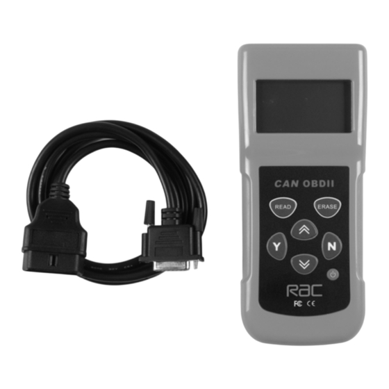
3. Product Information 3.1 Tool Description ⑴ LCD DISPLAY -- Indicates test results. Backlit, 128 x 64 pixel display with contrast adjustment. ⑵ Y BUTTON -- Confirms a selection (or action) from a menu. When a DTCs definition covers more than one screen, it is used to move down to the next screen for additional data. -
Page 11: Product Specifications
retrieved, moves up through the current screen to the previous screens for additional DTCs and definitions. ⑸ DOWN SCROLL BUTTON -- Moves down through menu and submenu items in menu mode. When more than one DTC is retrieved, moves down through the current screen to the next screens for additional DTCs and definitions. -
Page 12: Navigation Characters
3)OBD II cable -- Provides power to tool and communicates between tool and the vehicle 4) USB Cable -- Used to upgrade the scan tool 5) Carry Case -- A nylon case to store the scan tool when not in use 3.4 Navigation Characters Characters used to help navigate the scan tool are: 1) “►”... -
Page 13: Product Setup
2) Find DLC on vehicle. A plastic DLC cover may be found for some vehicles and you need to remove it before plugging the OBD2 cable. 3) Plug OBD II Cable into the vehicle’s DLC. 3.7 Product Setup The scan tool allows you to make the following adjustments and settings: 1) Contrast adjustment: Adjusts the contrast of the LCD display. - Page 14 Contrast Adjustment 1) From the System Setup menu, use the UP/DOWN scroll buttons to select Contrast, and press the Y button. 2) From the Contrast menu, use the UP/DOWN scroll buttons to decrease or increase the contrast. 3) Press the Y button to save your selection and return to previous menu.
- Page 15 Unit of Measurement 1) From the System Setup menu, use the UP/DOWN scroll buttons to select Unit of Measure and press the Y button. 2) From the Unit of Measure menu, use the UP/DOWN scroll buttons to select the desired unit of measurement. 3) Press the Y button to save your selection and return to previous menu.
- Page 16 2) Select Display Test from the Tool Self-Test menu and press the Y button. 3) Press the Y button again to start test. Look for missing spots in the solid black characters. 4) When completed, press the N button to return.
-
Page 17: Battery Replacement
B. Keyboard Test The Keyboard Test is used to verify that the keys are functioning properly. 1) Use the UP/DOWN scroll buttons to select Keyboard Test from the Tool Self-Test menu, and then press the Y button. 2) Press any key to start test. When you press a key, the key name should be observed on the display. -
Page 18: Vehicle Coverage
4) Reinstall battery cover by sliding battery cover on and installing screw. 3.9 Vehicle Coverage This RAC scan tool (Moboscan 8500) is specially designed to work with all OBDII compliant vehicles, including those equipped with the next-generation protocol -- Control Area Network (CAN). Under European legislation it is compulsory for all petrol vehicles since 2002 &... - Page 19 1) Turn the ignition off. 2) Locate the vehicle’s 16-pin Data Link Connector (DLC). 3) Plug into the scan tool cable connector to the vehicle’s DLC. 4) Turn the ignition on. But do not start the engine. 5) Turn the scan tool’s power on. 6) Press the Y button.
- Page 20 indicate “NO CODES ARE FOUND!” ● If there are any Diagnostic Trouble Codes present, a brief overview with the total count of the Trouble Codes, followed by that of the Fault Codes and Pending Codes will be reported on the display.
-
Page 21: Erasing Codes
specific codes), a message will be observed on the display. 11) If more than one DTC is found, use the UP/DOWN scroll buttons, as necessary, until all the codes have been shown up. 4.2 Erasing Codes CAUTION: 1. Erasing the Diagnostic Trouble Codes may allow the scan tool to delete not only the codes from the vehicle’s on-board computer, but also “Freeze Frame”... -
Page 22: Reading Freeze Frame Data
2)A warning message comes up asking for your confirmation. 3) If you do not want to proceed with erasing the codes, press the N button to exit. A message of “command cancelled” will show 4) If you do wish to proceed to erase the codes, then press the Y button. -
Page 23: Retrieving I/M Readiness Status
● If the scan tool is not connected or no communication is established with the vehicle yet, then refer to Reading Codes from 1 to 6 at Paragraph 4.1. If the retrieved information covers more than one screen, then a flashing down arrow will appear. - Page 24 1) Use the UP/DOWN scroll buttons to select I/M Status from the Vehicle Diagnosis menu and press the Y button. ● If the scan tool is not connected yet, then refer to Reading Codes in section 4 2) Use the UP/DOWN scroll buttons, as necessary, to view the status of the MIL light (“ON”...
-
Page 25: Viewing Vehicle Information
3) Press the N button to return to the Vehicle Diagnosis Menu. 4.5 Viewing Vehicle Information The View Vehicle Information function allows you to retrieve the Vehicle Identification No. 1) Use the UP/DOWN scroll buttons to select Vehicle Infor. From the Vehicle Diagnosis menu and press the Y button. -
Page 26: Saving Scan Results
4.6 Saving Scan Result This function allows you to store scanning results for off-car review and analysis. You can store up to 15 scanning events. 1) Use the UP/DOWN scroll buttons to select Save Scan Result from the Vehicle Diagnosis menu and press the Y button. ●... - Page 27 ● A scanning record will be identified by the selected vehicle manufacturer and the number of DTCs retrieved. For example: Ford:01 means that the vehicle scanned is a Ford with one DTC detected. If the retrieved DTCs contain any manufacturer specific codes and so a vehicle manufacturer has to be selected when viewing DTC definitions, then you won’t be prompted to select a vehicle manufacturer since the record will be identified...
-
Page 28: Rescanning Data
4.7 Rescanning Data The RESCAN function allows you to retrieve the most current data stored in the ECU or to re-link to the vehicle. Please use The RESCAN function when you meet the following situation in the process of retrieving DTCs: ---communications is disconnected with no reason;... - Page 29 2) If you want to read the last stored record (if there is any), select [YES] by pressing the Y button. Use the UP/DOWN scroll button to select [NO] and press the Y button to choose other stored records. 3) Use the UP/DOWN scroll buttons to select the record you want to view.
-
Page 30: Data Stream
4.9 Data stream The view Data function allows real time viewing of the vehicle’s computer module’s PID data. As the computer monitors the vehicle, information is simultaneously transmitted to scan tool Below is the PID retrieved by this scanner : CALC LOAD Calculated LOAD Value COOLANT... - Page 31 Helpline at the number above for advice. This product is not guaranteed for HIRE purposes. Manufactured under license for: Hilka Pro Imports 1 ROEBUCK PLACE, ROEBUCK ROAD, CHESSINGTON, SURREY KT9 RAC-HP104 - Issue 1 - R.W. 21-04-08...
Need help?
Do you have a question about the RAC-HP104 and is the answer not in the manual?
Questions and answers