Table of Contents
Advertisement
EPLC9600-
8 Channel PT-100 Scanner
- 128 x 64 Graphical LCD display
- 8 PT-100 temperature sensor inputs
- ON-OFF control
- Relay or (pnp "source") transistor output
- Sensor error detection
- Adjustable temperature offset
- 3 Different alarm and pre-alarm types for each channel
(High, Low and Band Alarms)
- User defined channel labels
- Display scan modes
- Operating with Real Time Clock (RTC)
- ModBus RTU communication protocol
(RS-232, RS-485 and Ethernet communication)
- Data Logging to USB Flash Memory
- Adjustable data logging time interval
- Password protection for programming mode
CHANNEL8
Introduction Manual. ENG EPLC-9600 CHANNEL8 V04 07/13
96 x 96 DIN 1/4
Advertisement
Table of Contents

Summary of Contents for EMKO EPLC9600-CHANNEL8
- Page 1 EPLC9600- CHANNEL8 96 x 96 DIN 1/4 8 Channel PT-100 Scanner - 128 x 64 Graphical LCD display - 8 PT-100 temperature sensor inputs - ON-OFF control - Relay or (pnp “source”) transistor output - Sensor error detection - Adjustable temperature offset - 3 Different alarm and pre-alarm types for each channel (High, Low and Band Alarms) - User defined channel labels...
- Page 2 ABOUT INSTRUCTION MANUAL Instruction manual of EPLC9600-CHANNEL8 consists of two main sections. Explanation of these sections are below. Also, there are other sections which include order information and technical specifications of the device. All titles and page numbers in instruction manual are in “CONTENTS”...
-
Page 3: Table Of Contents
3.2.2 DEVICE WITH TRANSISTOR OUTPUTS 3.3 SUPPLY VOLTAGE INPUT CONNECTION OF THE DEVICE 3.4 SUPPLY VOLTAGE INPUT CONNECTION OF TRANSISTOR OUTPUTS 3.5. GALVANIC ISOLATION TEST VALUE OF EPLC9600-CHANNEL8 WITH RELAY OUTPUTS 3.6. GALVANIC ISOLATION TEST VALUE OF EPLC9600-CHANNEL8 WITH TRANSISTOR OUTPUTS 4. - Page 4 EU DECLARATION OF CONFORMITY Manufacturer’s Name : EMKO ELEKTRONIK A.S. Manufacturer’s Address : DOSAB, Karanfil Sk., No:6, 16369 Bursa, TURKEY The manufacturer hereby declares that the product: Product Name : CHANNEL8 (8 Channel PT-100 Scanner) Type Number : EPLC9600 Product Category...
-
Page 5: General Specifications
1.Preface EPLC9600-CHANNEL8 series 8 channel PT100 scanner devices are designed for measuring and logging temperature. They can be used in many applications with their PT-100 process input, alarm outputs, selectable alarm functions, RS-232 / RS-485 / Ethernet / USB communications. -
Page 6: Ordering Information
U USB (USB2.0 “for temperature data logging”) 1.3 Warranty EMKO Elektronik warrants that the equipment delivered is free from defects in material and workmanship. This warranty is provided for a period of two years. The warranty period starts from the delivery date. This warranty is in force if duty and responsibilities which are determined in warranty document and instruction manual performs by the customer completely. -
Page 7: Installation
2.Installation Before beginning installation of this product, please read the instruction manual and warnings below carefully. In package , - One piece unit - Two pieces mounting clamps - One piece instruction manual A visual inspection of this product for possible damage occured during shipment is recommended before installation. -
Page 8: General Description
(maximum thickness 15 mm / 0.59 inch) Front Panel IP65 protection NEMA 4X Front View and Dimensions of EPLC9600-CHANNEL8 Maximum 15 mm / 0.59 inch +/- . ü 96 mm / 3.78 inch 12 ± 1 mm / 0.47 inch... -
Page 9: Panel Cut-Out
2.3 Panel Cut-out 129 mm / 5.08 inch (min) 92mm / 3.62 inch... -
Page 10: Environmental Ratings
2.4 Environmental Ratings Operating Conditions Operating Temperature : 0 to 50 °C Max. Operating Humidity : 90% Rh (non-condensing) Altitude : Up to 2000m. Forbidden Conditions: Corrosive atmosphere Explosive atmosphere Home applications (The unit is only for industrial applications) 2.5 Panel Mounting 1-Before mounting the device in your panel, make sure that the cut-out is of the right size. -
Page 11: Installation Fixing Clamp
2.6 Installation Fixing Clamp The unit is designed for panel mounting. 1-Insert the unit in the panel cut-out from the front side. 2- Insert the mounting clamps to the holes that located top and bottom sides of device and screw up the fixing screws until the unit completely immobile within the panel... -
Page 12: Terminal Layout And Connection Instructions
3.Electrical Wirings You must ensure that the device is correctly configured for your application. Incorrect configuration could result in damage to the process being controlled, and/or personal injury. It is your responsibility, as the installer, to ensure that the configuration is correct. Device parameters has factory default values. -
Page 13: Electrical Wiring Diagram
3.2 Electrical Wiring Diagram 3.2.1 Device with Relay Outputs Electrical wiring of the device must be the same as ‘Electrical Wiring Diagram’ below to prevent damage to the process being controlled and personnel injury. Power Supply Input 100...240V V (- %15;+%10) 50/60Hz 7VA 24VV(-%15;+%10) 50/60Hz 7VA 24VZ(-%15;+%10) 7W Process Inputs... -
Page 14: Device With Transistor Outputs
3.2.2 Device with Transistor Outputs Electrical wiring of the device must be the same as ‘Electrical Wiring Diagram’ below to prevent damage to the process being controlled and personnel injury. Power Supply Input 100...240V V (- %15;+%10) 50/60Hz 7VA 24VV(-%15;+%10) 50/60Hz 7VA 24VZ(-%15;+%10) 7W Process Inputs (It must be determined in order.) -
Page 15: Supply Voltage Input Connection Of The Device
3.3 Supply Voltage Input Connection of the Device Note-2 External Fuse (1 A T) Power Supply Switch Power Supply 100-240V V (- %15;+%10) 50/60Hz 7VA or, 24VV(-%15;+%10) 50/60Hz 7VA or, 24VZ(-%15;+%10) 7W 100-240 V V 50/60Hz Note-1 :There is an internal 33R W fusible flameproof resistor in There is an internal 4R7 W fusible flameproof resistor in 24VW 50/60Hz “L”... -
Page 16: Supply Voltage Input Connection Of Transistor Outputs
3.4 Supply Voltage Input Connection of the Transistor Outputs This power supply connection is need only when transistor type outputs are used. Power Supply Switch Supply Voltage 24V Z ( 15%) ± Note-1 : External fuse is recommended. Note-2 : Fuse value must be select according to the system. -
Page 17: Galvanic Isolation Test Value Of Eplc9600-Channel8 With Relay Outputs
3.5 Galvanic Isolation Test Values of EPLC9600-CHANNEL8 with Relay Outputs Supply Input of Device 2000V V Analog inputs 2000V V Relay Outputs 2000V V RS 232 2000V V RS 485 2000V V 2000V V Ethernet... -
Page 18: Galvanic Isolation Test Value Of Eplc9600-Channel8 With Transistor
3.6 Galvanic Isolation Test Values of EPLC9600-CHANNEL8 with Transistor Outputs 2000V V Supply Input Supply Input of Device of Output Card 2000V V 500V V Analog inputs 2000V V Transistor Outputs 500V V 2000V V RS 232 500V V 2000V V... -
Page 19: Cable Connection Between Rs232 Terminal Of The Device And Pc
4. Cable Connection Between RS-232 Terminal of the Device and PC PC (Personal Computer) 9 Pin DCON connection Cable Lenght must be max. 12 meters for 9600 baud rate... -
Page 20: Connection For Rs485 Serial Communication
5. Connection for RS-485 Serial Communication PC(Personal Computer) RS-232 Ş RS-485 Convertor RS-232 SLAVE-1 Connection MASTER Cable 32 terminal can be connected in RS-485 line Rt resistor = 120 W For communication connection Twisted Pair cable must be used Cable lenght can be maximum 1000 meters in 9600 baud rate. -
Page 21: Definetion Of The Front Panel And Accessing To The Parameters
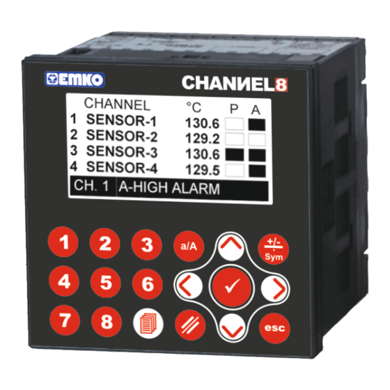
6. Definetion of the Front Panel and Accessing to the Parameters 6.1. Definition of Front Panel 128 x 64 Pixel Graphical LCD Standard Channel Function Selection Buttons Buttons Programming Mode Access Button ENTER BUTTON ü This button is used to confirm the variable value in variable value changing screen. ESCAPE BUTTON This button is used to exit from variable value changing screen to preceding visualization screen without saving variable value, and return to main operation screen. - Page 22 6.2. Main Operation Screens Definetion If the display type parameter value DSP.TYPE = 1 Process Value Pre-Alarm Status Analog Channels Alarm Status Names Analog Channels Numbers Alarm Messages MAIN OPERATION SCREEN-1 Press right button for accessing the main operation screen-2 MAIN OPERATION SCREEN-2 Press left button for accessing the main...
- Page 23 If the display type parameter value DSP.TYPE = 2 Analog Channels Analog Channels Names Numbers Process Value Set Value Alarm Messages MAIN OPERATION ( CHANNEL-1 SCREEN) Press number (1,2,3,4,5,6,7 or 8) buttons for accessing the relevant channel MAIN OPERATION ( CHANNEL-4 SCREEN) screen.
-
Page 24: Main Operation Screen Definetion
6.3. Accessing to the Operator Parameter Pages OPERATOR PARAMETERS SECTION MAIN OPERATION SCREEN PASSWORD SCREEN When programming mode access button is pressed Press right or left and released before 5 seconds is expire, If operator button for selecting the password is different from 0, operator parameter password parameter. - Page 25 OPERATOR PARAMETER SCREEN (CHANNEL-1 PARAMETERS) PARAMETER ENTERING SCREEN Minimum Maximum 100.0 C -200.0 650.0 100.0 1.0.1 ü Press enter button for accessing to Change the parameter value parameter entering screen. with cursor (lef, right, up and down) buttons. OPERATOR PARAMETER SCREEN (CHANNEL-1 PARAMETERS) PARAMETER ENTERING SCREEN Minimum...
-
Page 26: Accessing To The Technician Parameter
6.4. Accessing to the Technician Parameter Pages TECHNICIAN PARAMETERS SECTION MAIN OPERATION SCREEN PASSWORD SCREEN When programming mode access button is pressed Press right or left for 5 seconds, If technician password is different from button for selecting the 0, technician parameter section password screen will password parameter. - Page 27 TECHNICIAN PARAMETER SCREEN TECHNICIAN PARAMETER SCREEN (PAGE - 2) (PAGE - 3) Press down button for accessing next Press down button for accessing next parameter page, press up button for parameter page, press up button for accessing previous parameter page. accessing previous parameter page.
- Page 28 TECHNICIAN PARAMETER SCREEN TECHNICIAN PARAMETER SCREEN (PAGE - 8 “ETHERNET PAGE”) (PAGE - 9 “RTC PAGE”) Press down button for accessing next Press up button for accessing parameter page, press up button for previous parameter page, accessing previous parameter page. press escape button for return to main operation screen.
-
Page 29: Operator Pages Parameters Definetions
6.5. Operator Pages Parameters Definetions Analog Channel Number 1.0.1 Channel Selection Buttons Parameter Explanation Unit Default ALARM SET Alarm Set Value For Channel-X -200.0 650.0 100.0 PRE. A. SET Pre-Alarm Set Value For Channel-X -200.0 650.0 90.0 DSP. BACKLIGHT Display Backlight Mode CONTRAST Display Contrast Value ALARM SET... -
Page 30: Technician Pages Parameters Definetions
6.6. Technician Pages Parameters Definetions 6.6.1. Page-1 Parameters Technician Parameter Analog Channel Page Number Number Channel Selection Buttons Parameter Explanation Unit Default ALARM TYPE Alarm Type For Channel-X PRE. A. TYPE Pre-Alarm Type For Channel-X HYSTERESIS Hysteresis Value For Channel-X -400.0 400.0 BAND ALARM... - Page 31 Alarm Type Selection Parameters Band Alarm Selection Parameters Modbus Addresses Modbus Addresses Modbus Address Modbus Address Parameter Name Parameter Name * ( ) CH-1 ALARM TYPE 42082 CH-1 BAND ALARM 42053 * ( ) CH-2 ALARM TYPE 42085 CH-2 BAND ALARM 42057 * ( ) CH-3 ALARM TYPE...
-
Page 32: Page-2 Parameters
6.6.2. Page-2 Parameters Explanation Parameter Unit Default Address TECH. PW. Technician Section Password 9000 42106 OPR. PW. Operation Section Password 9000 42107 42128 DSP. TYPE Main Operation Screen Type DSP. SCAN Display Scan ON/OFF ON/OFF 42129 SCAN TIME Display Scan Period SEC. -
Page 33: Page-3 And Page-4 Parameters
6.6.3. Page-3 and Page-4 Parameters Channel Names Channel Enable/Disable Selection Channel Numbers Explantion Parameter Unit Default Address String CH-1 NAME Channel-1 Name SENSOR-1 42000 - 42004 String CH-2 NAME Channel-2 Name SENSOR-2 42005 - 42009 String CH-3 NAME Channel-3 Name SENSOR-3 42010 - 42014 String... -
Page 34: Rs232 Setup Pages Parameters
6.6.4. RS232 Setup Pages Parameters Explanation Parameter Unit Default Address BAUDRATE Baudrate For RS232 Communication 42124 PARITY Parity For RS232 Communication 42125 42126 STOP BIT Stop Bit For RS232 Communication ID For RS232 Communication 42127 BAUDRATE Modbus communication baudrate for RS232 is can be adjusted by this parameter. If parameter value, 1 = 4800 2 = 9600 3 = 19200... -
Page 35: Rs485 Setup Pages Parameters
6.6.5. RS485 Setup Pages Parameters Explanation Parameter Unit Default Address BAUDRATE Baudrate For RS485 Communication 42132 PARITY Parity For RS485 Communication 42133 42134 STOP BIT Stop Bit For RS485 Communication ID For RS485 Communication 42135 BAUDRATE Modbus communication baudrate for RS485 is can be adjusted by this parameter. If parameter value, 1 = 4800 2 = 9600 3 = 19200... -
Page 36: Usb Setup Pages Parameters
6.6.6. USB Setup Page Parameters Explanation Unit Default Address Parameter String FILE NAME USB File Name CHAN8.txt 42040 - 42044 String LABEL USB Label SAMPLE 42045 - 42049 SAVE TIME USB Time Record ENA/DIS 42137 3600 42138 SAMP. TIME USB Record Time Interval Sec. -
Page 37: Ethernet Setup Pages Parameters
6.6.7. ETHERNET Setup Page Parameters Explanation Unit Default Address Parameter DHCP DHCP Enable /Disable ENA/DIS 42150 ETH. PORT ETHERNET Port No 65535 42151 ETH. IP NO Ethernet IP No 192.168.0.250 42152 - 42153 ETH. NETMASK Ethernet Netmask 255.255.255.0 42154 - 42155 ETH. - Page 38 6.6.8. REAL TIME (RTC ) Setup Page Parameters Press and hold on 3 seconds Enter button for ü setting the RTC time value. Parameter Explanation Unit Default YEAR Year Value For RTC Time 2010 3000 MONTH Month Value For RTC Time Day Value For RTC Time HOUR Hour Value For RTC Time...
-
Page 39: Operation Graphics Of Alarm And Pre-Alarm Type
7. Operation Graphics of Alarm and Pre-Alarm Types High Alarm Alarm Output Process Value Low Alarm Alarm Output Process Value Band Alarm Alarm Output Process Value (SET - (BAND/2)) (SET + (BAND/2)) SET = Alarm or Pre-Alarm Set value HYS = Hysteresis value for Alarm and Pre-Alarm output BAND= Bandwidth for Band Alarm. -
Page 40: Output Addresses
8. Modbus Addresses 8.1. Output Addresses Unit Default Address OUTPUT ADDRESSES CH-1 ALARM OUT Channel-1 Alarm Output Status 00001 CH-2 ALARM OUT Channel-2 Alarm Output Status 00002 00003 CH-3 ALARM OUT Channel-3 Alarm Output Status CH-4 ALARM OUT Channel-4 Alarm Output Status 00004 CH-5 ALARM OUT Channel-5 Alarm Output Status... -
Page 41: Specifications
Emko Elektronik Sanayi ve Ticaret A.Ş. Demirtaş Organize Sanayi Bölgesi Karanfil Sk. No:6 16369 BURSA/TURKEY Phone : +90 224 261 1900 Fax : +90 224 261 1912 Thank you very much for your preference to use Emko Elektronik Products. Your Technology Partner www.emkoelektronik.com.tr...
Need help?
Do you have a question about the EPLC9600-CHANNEL8 and is the answer not in the manual?
Questions and answers