
Summary of Contents for Nivetec UNICONT PMM-500
- Page 1 UNICONT PMM-500 Universal process controller and display unit User's and Programming manual 1 edition pmm5111a0600p_01 1 / 32...
-
Page 2: Table Of Contents
TABLE OF CONTENTS 1. GENERAL DESCRIPTION........................3 2. ORDER CODE............................4 3. TECHNICAL DATA ...........................5 4. DIMENSIONS ............................6 5. MOUNTING ...............................6 6. WIRING..............................6 6.1 W ..........................6 IRING INSTRUCTIONS 6.2 W ....................7 IRING CHART OF THE OUTPUT VERSIONS 7. FRONT PANEL, KEYPAD, DISPLAYS ....................8 8. -
Page 3: General Description
We are sure that you will be satisfied throughout its use! 1. GENERAL DESCRIPTION The UNICONT PMM-500 universal display and controller instruments are 1/16 DIN (48x48mm) size, panel mountable, modern, easy of use microprocessor based devices supporting versatile functions. EEPROM memory ensures data- and program protection during power outages. -
Page 4: Order Code
2. ORDER CODE UNICONT PMM-500 series: UNICONT PMM-5 – NPUT OWER SUPPLY Universal 100-240 V AC (sensor or analogue) 20-48 V AC 22-65 V DC UTPUT R1, R2, analogue OUT UTPUT ESCRIPTION R1, R2, U R1, R2, R3 SPDT relay outputs... -
Page 5: Technical Data
3. TECHNICAL DATA Type PMM-5-- Pt100 RTD: -199 ºC...+800 ºC Thermocouple: J, T, K, L, N, B, R, S, C, Pt Rh Sensor, -240 ºC...+2320 ºC or analogue input Current: (DC) 4-20 mA, 0-20 mA Voltage: (DC) 0-50 mV, 10-50 mV, 0-5 V, 1-5 V, 0-10 V, 2-10 V Pt100 RTD: >10 MOhm, Input resistance... -
Page 6: Dimensions
4. DIMENSIONS The unit can be mounted into a suitable 1/16DIN (48x48 mm) cut- out place. Insertion length of the unit is 110mm, the additional dimensions can be seen on the drawing below. 5. MOUNTING The unit can be mounted with the help of the attached mounting accessory to the suitable cut-out hole. -
Page 7: Wiring Chart Of The Output Versions
6.2 W IRING CHART OF THE OUTPUT VERSIONS Outputs Type OUT1 OUT2 OUT3 OUTA Analogue PMM-511-□ 24V DC / 22mA PMM-512-□ Analogue 24V DC / 22mA PMM-513-□ PMM-514-□ NC C SSR1 SSR2 Analogue PMM-515-□ 10V DC / 20mA 10V DC / 20mA SSR1 SSR2 24V DC / 22mA... -
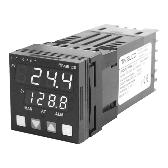
Page 8: Front Panel, Keypad, Displays
Wiring examples: 2-wire Pt 100 RTD, 1 relay output. OUT 1. 100-240V AC Pt100 2-wire 4-20 mA transmitter, power supply for transmitter, 2 pcs. relay output. OUT 3. 24VDC OUT 1. NO 100-240V AC 4-20mA 14 15 OUT 2. 3-wire voltage output transmitter, power supply for transmitter, 1 relay output, 1 analogue output. OUT 3. -
Page 9: Error Messages And Indications
Operation FLASHES LIGHTS Setup mode Manual mode Auto tuning mode Self-Tune mode Pre-Tune mode Alarm condition is present For Current Proportioned outputs, ON indicates primary power is >0% FLASHES in unison with Time Proportioning ▲ It turns ON when the stored Max. PV value is Primary outputs displayed on indicators For Current Proportioned outputs, ON secondary... -
Page 10: Programming Sequence
9. PROGRAMMING SEQUENCE 9.1 P OWERING UP FOR THE FIRST TIME Wait 2 minutes First turn ON Self-test Self-test Turn ON after replacing Automatic Entering Selecting the value of Configuration Normal an output... -
Page 11: Unlock Code
9.2.2 U NLOCK CODE To enter a required menu point press button then select the corresponding unlock code with and buttons. This procedure can prevent unauthorised entry to Configuration, Setup and Automatic Tuning modes. Entering an incorrect unlock code will result to return to Select Mode. The value of the lock codes only can be changed from within the modes that they apply to. -
Page 12: Information Mode
10.1 I NFORMATION This mode describes the instrument and the options fitted to it. It is advised to start Select Mode procedure with this point because toggling in the menu, hardware configuration, manufacturing data can be seen about the given instrument. ... - Page 13 DEFAULT PARAMETER ADJUSTMENT RANGE DISPLAY DISPLAY VALUE B tip. 100…1824 °C B tip. 211…3315 °F C tip. 0…2320 °C C tip. 32…4208 °F J tip. -200…120 °C J tip.-328…2192 ° F ...
- Page 14 DEFAULT PARAMETER ADJUSTMENT RANGE DISPLAY DISPLAY VALUE Control Type Single outputs can drive the PV in one direction only (e.g. heat only, cool only, increase humidity etc) Dual outputs can force the PV to increase or decrease (e.g heat &...
- Page 15 DEFAULT PARAMETER ADJUSTMENT RANGE DISPLAY DISPLAY VALUE Deviation Alarm Reverse action Alarm Direct action Alarm Down Reverse action Alarm Direct action Alarm Band Alarm Reverse action Alarm Direct action Alarm No alarm Process High Range Min. to Range Max. Range ...
- Page 16 DEFAULT PARAMETER ADJUSTMENT RANGE DISPLAY DISPLAY VALUE Deviation ±span from setpoint Alarm 1 Value Only visible when = set Parameter is repeated in Set-up Mode Band Alarm 1 Value 1 LSD to full span from setpoint Only visible when ...
- Page 17 DEFAULT PARAMETER ADJUSTMENT RANGE DISPLAY DISPLAY VALUE Deviation ±span from setpoint Alarm 2 Value Only visible when = set Parameter is repeated in Set-up Mode Band Alarm 2 Value 1 LSD to full span from setpoint Only visible when ...
- Page 18 DEFAULT PARAMETER ADJUSTMENT RANGE DISPLAY DISPLAY VALUE Loop Alarm Time 1 sec to 99 mins. 59secs 99.59 Only visible when Only applies if primary proportional band =0 = set Parameter is repeated in Set-up Mode Alarm Inhibit ...
- Page 19 DEFAULT PARAMETER ADJUSTMENT RANGE DISPLAY DISPLAY VALUE Alarm1. és (AND) Alarm 2. Alarm1 Direct Reverse Alarm Alarm Alarm Alarm OUT2 Alarm2 Direct Alarm1 Alarm2 Reverse Retransmit SP or PV Output if = Linear Output 2 Range ...
- Page 20 DEFAULT PARAMETER ADJUSTMENT RANGE DISPLAY DISPLAY VALUE Retransmit SP or PV Output if = Output 3 PV 0-5 V DC OUT3 0-10 Retransmit Type 0-10 V DC OUT3 Only visible when 2-10 V DC OUT3 ...
-
Page 21: Set - Up Mode
10.3 S This mode is normally selected only after Configuration Mode has been completed, or is used when a change to the process set up is required. These parameters must be set as required before attempting to use the indicator in an application. When in Set-up Mode, the MAN LED indicator flashes. - Page 22 DEFAULT PARAMETER PV-DISPLAY ADJUSTMENT RANGE DISPLAY VALUE Overlap/Deadband Defines the portion of Pb_P primary Only visible when Pb_S OUT1. OUT2. secondary ≠ 0.0 or = proportional bands ) ( over which both OUT2. OUT1. outputs active Overlap (Overlap), or neither is (positive value)
- Page 23 DEFAULT PARAMETER PV-DISPLAY ADJUSTMENT RANGE DISPLAY VALUE Output 2 Cycle Time 0.5, 1, 2, 4, 8, 16, 32, 64, 128, 256 or 512 secs. Only visible when Not applicable to linear outputs. = , or = Output 3 Cycle Time 0.5, 1, 2, 4, 8, 16, 32, 64, 128, 256 or 512 secs.
- Page 24 DEFAULT PARAMETER PV-DISPLAY ADJUSTMENT RANGE DISPLAY VALUE Deviation Alarm 2 Value ±span from setpoint Only visible when = set Parameter is repeated in Configuration Mode Band Alarm 2 Value 1 LSD to full span from setpoint Only visible when ...
-
Page 25: Auto -Tuning (At) Mode
10.4 A (AT) M UNING Automatic Tune Mode is selected when it is desired to use the Pre-tune and Self-tune facilities on a controller to assist the user in setting up Proportional band, Integral and Derivative parameter values. Refer to the following Automatic Tune Mode table. Navigating in Automatic Tune Mode: ... -
Page 26: Manual Fine Tuning Of Pid Parameters
Check that the Setpoint Upper Limit () and Setpoint Lower Limit () are set to safe levels for the process. Adjust if required Select ON-OFF control (=0) Switch on the process. The process variable will oscillate about the setpoint. Record the Peak-to-Peak variation (P) of the first cycle (i.e. -
Page 27: Operator Mode
10.7 O PERATOR This is the normal operating mode of the instrument from power-up. It can also be accessed from any other mode via Select Mode as follows. In order to provide proper operation, all parameters should be configured in the Configuration Mode and Set-up Mode before using the Operator Mode! From any Mode if there is no key activity for 2 minutes the controller automatically returns to operator mode! - Page 28 Display mode 3. value Setpoint alue display Adjust the etpoint Actual etpoin alue rame ate if Adjust the Adjust value or etpoint alue Alarms Alarm 2. ON Loop Alarm ON ...
-
Page 29: Manual Mode
Manual power is not limited by the (Primary Power Output Limit) parameter. 11. COMMUNICATION Some types of UNICONT PMM-500 controllers has RS485 communication module (as per order codes) (OUT A module). For a complete description of the Modbus protocol refer to the description provided at http://www.modbus.org... -
Page 30: Modbus
11.2 M ODBUS OMMUNICATION The unit uses the following Modbus functions: MODBUS DECIMAL PARAMETER MODBUS MEANING DESCRIPTION FUNCTION CODE FORMAT Read output/input status bits at given 01/02 Read coil/ Input status address Read current binary value of specified number of parameters at given 03/04 Word Read holding/Input registers... -
Page 31: Word Parameters
11.3.2 W ARAMETERS MODBUS PARAMETER CONTROLLING NOTES PARAMETER NUMBER MODE Process Variable Current value of PV If under-range = 62976, If over-range = 63232 Setpoint Value of currently selected setpoint. Target setpoint if ramping. Output Power 0% to 100% for single output; -100% to +100% for dual output control. - Page 32 MODBUS PARAMETER CONTROLLING NOTES PARAMETER NUMBER MODE Equipment ID 6100 Interior code 4 characters Interior code 4 characters Interior code 4 characters Interior code 4 characters Interior code 16 characters Interior code 16 characters Input status Input status. Read Only. Bit 0: Sensor break flag Bit 1: Under-range flag Bit 2: Over-range flag...
Need help?
Do you have a question about the UNICONT PMM-500 and is the answer not in the manual?
Questions and answers