Table of Contents
Advertisement
Advertisement
Table of Contents

Summary of Contents for AGA GATEMASTER 900 HD
- Page 1 AGA GATEMASTER 900 HD Installation Manual AGA GATEMASTER 900 HD...
-
Page 2: Contact Information
You agree to properly install this product and that if you fail to do so Amazing Gates of America, LLC (“AGA”) shall in no event be liable for direct, indirect, incidental, special or consequential damages or loss of profits whether based in contract tort or any other legal theory during the course of the warranty or at any time thereafter. - Page 3 WARNINGS! A wired photo eye sensor must be installed for this gate operator to function properly (UL325-2016) Make sure that the gates are level and swing freely. Keep your hinges greased. Do not let children operate or play with the automatic gate system. Do not cross the path of the gate when operating.
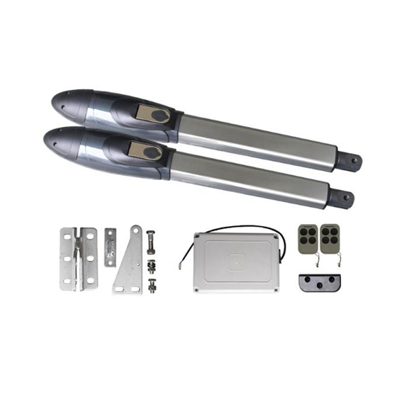
- Page 4 THE AGA GATEMASTER 900 AUTOMATIC SWING GATE SYSTEM Product Description and Applications This system is for residential or light commercial automation of a swinging gate. Technical Specifications: Motor: 24V DC motor with mechanical release Gear type: worm gear Max absorbed power: 144W...
-
Page 5: Installation
Installation Make sure the gate is level and swings freely. The gate must not have a wheel. Determine if it will be a pull-to-open (swing in) or a push-to-open (swing out) setup. Typically, the gate will swing in toward the house, which is a pull-to-open setup. Sometimes the gate must swing out towards the street, for example when the driveway slopes up to the house, which is a push-to-open setup. - Page 7 PULL-To-Open Installation Steps This is for a gate that will swing in towards the house. The operator is mounted on the inside and pulls the gate open. NOTE: The operator shaft will be fully extended when the gate is closed and fully retracted when the gate is open.
- Page 8 ◼ Assemble the post bracket, but hand tighten the bolts for now to allow adjustment to be made ◼ Open the gear motor cover and take out the mounting pin ◼ Attach the post bracket to the operator arm ◼ Attach the gate bracket to the operator arm ◼...
- Page 9 ◼ Using a clamp, mount the gate bracket onto the gate. Do not drill and bolt yet. ◼ Attach the operator arm to the brackets again. ◼ With the release lever up, move the gates manually open and closed and adjust the brackets until the gate opens and closes in the correct position.
- Page 10 ◼ Open the gear motor cover and take out the mounting pin ◼ Attach the Post Bracket to the operator arm ◼ Attach the Gate Bracket to the operator arm. First, tighten the bolt all the way, and then loosen it ½ turn so there is tension, but it can still turn.
- Page 11 ◼ Using a clamp, mount the gate bracket onto the gate. Do not drill and bolt yet. ◼ Attach the operator arm to the brackets again ◼ With the release lever up, move the gates manually open and closed until they are in the desired position ◼...
-
Page 12: Solar Power
extends out of the bottom of the control box. Connection should be made in a weather tight junction box. All high voltage wiring must be in conduit. The cables for the safety photo beam, exit wand, wired keypad and wired intercom are not required to be placed in conduit but it is highly recommended to do so in order to protect them and to be able to more easily replace them. -
Page 13: Battery Backup
The Charge Controller stops charging the batteries when they exceed a set high voltage level, and re-enable charging when battery voltage drops back below that level. Press left/menu button to step through the settings. The main display shows the current level of the battery in Volts. Press the left/menu button once to see the Float or CV voltage. -
Page 14: Mount The Control Box
Mount the Control Box Locate and mount the control box somewhere close to the primary operator arm. Also mount a weatherproof junction box underneath the control box for 110V AC. Run the Operator Arm Cables to the Control Box Run the two-conductor cable from the operator arms to the control box. Only two conductors are needed for each arm. - Page 15 Installing the AGA GATEMASTER Keypad NOTE: Have the keypad in hand at the gate control box when programming. Do not mount keypad on gooseneck mounting post yet.
- Page 16 How to change the programming code: Enter the current installer code, for example 0000 (expect one long beep) Press 69# (expect one short beep) Key in new 4-digit installer code followed by the # key for example 4640# (expect one long beep and one short beep) Keypad will automatically exit programming mode Installing Safety Photo Eye We offer two types of photo eyes: through-beam and reflector.
- Page 17 Connect Common on the photo eye to COM (5) on the control board. (All Commons and Negatives from all photo eyes connect to the same terminal COM (5) on the control board.) Test the photo eyes by activating the gate and then blocking the beam. The gate will reverse.
-
Page 18: Installing A Radio Receiver
For a Single gate: Output 1 N.O. --- “SIDE1” (3) Output 1 COM --- “COM” (5) Positive + --- “VCC” (10) Negative - --- “GND” (11) (Could also use “SWIPE” but then you can’t close the gate by keying in the code again.) Installing a Radio Receiver The control board includes its own radio receiver, and two remotes come with the system. -
Page 20: Control Board Description
THE AGA GATEMASTER 900 AUTOMATIC SWING GATE SYSTEM Control Board Description 2SIDE terminal is used for connecting accessories when the gate is a double gate COM terminal is COMMON, used for connecting the “ground” or COM connection of accessories 1SIDE terminal is used for connecting accessories when the gate is a double gate Swipe Card terminal is used for connecting accessories to open the gate COM terminal is COMMON, used for connecting the “ground”... -
Page 21: Control Board Settings
Motor1- terminal is used for connecting the secondary operator arm (actuator) (-) Motor1+ terminal is used for connecting the secondary operator arm (actuator) (+) Motor2 + terminal is used for connecting the primary operator arm or for use with a single gate; positive (+) Motor2 - terminal is used for connecting the primary operator arm or for use with a single gate;... - Page 22 P1 - 6 (applies to secondary arm at low speed) P2 -10 (applies to secondary arm at high speed) P3 - 6 (applies to primary arm at low speed) P4 -10 (applies to primary arm at high speed) P5 - Sets the high-speed running time. This allows the gate to run at its highest speed for however many seconds you set before slowing down.
- Page 23 Factory default is set to 0 which is .5 second. 1 is 5 seconds. PC – Radio Receiver Mode - Controls whether the wireless keypad and remote transmitters will open a Single gate or Double gate 0 = Disables opening by the remote or keypad. 1 = Single gate mode 2 = Double Gate Mode 3 = Top Left Remote button only opens Primary side;...
Need help?
Do you have a question about the GATEMASTER 900 HD and is the answer not in the manual?
Questions and answers