Table of Contents

Summary of Contents for SRP aero Lynx VTOL
-
Page 1: Table Of Contents
Table of Contents Introduction General Information Welcome Package Contents Hardware Features Software Features Getting Started GCS Overview Preflight Flying 1.10 M ission Planning 1.10.1 Changing Flight M odes 1.10.2 Available Flight M odes 1.10.3 Data Links 1.10.4 Reconnecting in Flight 1.10.5 Failsafes 1.10.6 Warnings 1.10.7 Landing 1.11 Payloads 1.12 Standard M apping Payload 1.12.1 M ultispectral M apping Payload 1.12.2 Custom Payloads 1.12.3 Post Processing... - Page 2 Calibration 1.15.9 Appendixes 1.16 Simulator 1.16.1 Flying with other GCS's 1.16.2 Status LED M eanings 1.16.3 Getting Logs 1.16.4 System Limitations 1.16.5 M anual Changelog 1.16.6 Glossary 1.16.7...
-
Page 3: Introduction
Introduction Lynx VTOL User M anual Last Updated: 18 November 2019 Copyright © 2013-2019 Swift Radioplanes, LLC A PDF version of this manual is available here. -
Page 4: General Information
General Information GENERAL INFORMATION READ THIS US ER MANUAL CAREFULLY BEFORE US ING LYNX VTOL. Applicable Regulations Unmanned Aircraft are subject to regulations enforced by civil aviation authorities. Regulations may vary depending on the country where you intend to operate your product. ANY USE OF SWIFT RADIOPLANES LLC PRODUCTS IN BREACH OF THE LAW OF THE COUNTRY WHERE YOU OPERATE THE PRODUCT IS UNDER YOUR SOLE RESPONSIBILITY . INFORM YOURSELF BEFORE USING THE PRODUCT. SOM E COUNTRIES M AY HAVE LAWS THAT LIM IT THE USE OF UNM ANNED AIRCRAFT TO LINE-OF-SIGHT OPERATIONS AND/OR PROHIBIT THE USE OF UNM ANNED AIRCRAFT AT ALL OR IN SPECIFIC AREAS/AIRSPACE. Limited Warranty and Service Agreement The limited warranty and service agreement can be found at srp.aero/policy Limitation of Liability SWIFT RADIOPLANES SHALL NOT BE LIABLE FOR SPECIAL, INDIRECT, INCIDENTAL OR CONSEQUENTIAL DAM AGES, LOSS OF PROFITS OR PRODUCTION OR COM M ERCIAL LOSS IN ANY WAY , REGARDLESS OF WHETHER SUCH CLAIM IS BASED IN CONTRACT, WARRANTY , TORT, NEGLIGENCE, STRICT LIABILITY OR ANY OTHER THEORY OF LIABILITY , EVEN IF SWIFT RADIOPLANES HAS BEEN ADVISED OF SUCH DAM AGES. Further, in no event shall the liability of Swift Radioplanes exceed the individual price of the Product on which liability is asserted. As Swift Radioplanes has no control over use, setup, nal assembly, modication or misuse, no liability shall be assumed nor accepted for any resulting damage or injury. By the act of use, setup or assembly, the User accepts all resulting liability. If you as the Purchaser or the User are not prepared to accept the liability associated with the use of the Product, Purchaser is advised to return the Product immediately in new and unused condition to the place of purchase. Copyright Swift Radioplanes LLC reserves the right to make changes to specifications and product descriptions contained in this document at any time without notice. Please visit srp.aero or contact support@srp.aero for the latest revision. Copyright © 2019 Swift Radioplanes LLC. -
Page 5: Welcome
Welcome Welcome Congratulations on your purchase of the Lynx VTOL. Lynx VTOL is a vertical takeoff and landing fixed-wing unmanned aircraft for precision aerial mapping. Lynx VTOL blends the ease-of-use and flexibility of a multirotor with the endurance and speed of an airplane. This revision of the manual refers to version 0.6.0 of Swift GCS software. Check the software version included in your package and consult the Swift GCS release notes for potential changes included in more recent versions of the software. -
Page 6: Package Contents
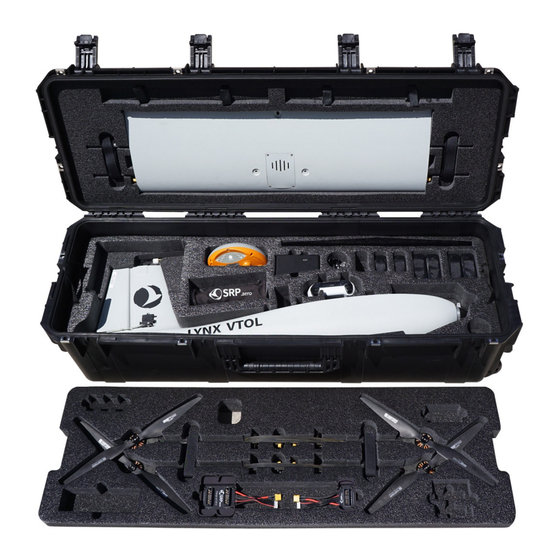
Package Contents Package Contents... - Page 7 Package Contents The standard Lynx VTOL utilizes an SKB 3i-4213-12 rugged transport case and contains the following items: M ain body fuselage with integrated autopilot Center wing Left wing Right wing Stabilator (horizontal tail) Left VTOL motor boom Right VTOL motor boom 4x Lithium Ion battery packs (main battery) 2x Lithium Polymer battery packs (VTOL battery) Battery charger (for main and VTOL batteries) Tool bag Tool kit Philips screwdriver Flathead screwdriver Crescent wrench 2.5mm hex key Pitot tube cover...
- Page 8 Package Contents Lens brush (optional with payload) Spares kit 4x pitot tube clips 2x tail clips 2x wing clips 2x 4-40 x 1/2" screws (for pitot and wing clips) 8x front wing thumbscrews 4x rear wing thumbscrews 4x motor boom thumbscrews 1x pair folding propellers M icro SD card adapter USB micro cable USB-C cable Ground telemetry radio with antennas RC controller (optional) Gamepad (optional) Payload (optional) GNSS base station (optional) GeoTagz license and dongle (only with PPK option) Depending on your order, your package may also include other items, such as additional payloads. Please verify you packing list upon delivery. Contact support@srp.aero immediately if anything is missing.
-
Page 9: Hardware Features
Hardware Features Hardware Features The Lynx VTOL airframe consists of the following components. Fuselage: The Lynx VTOL fuselage is the main body of the airframe and contains the majority of electronics, including the autopilot and payload. Left/Right Wing: The wings provide lift for the aircraft when in forward flight. Each contains a servo actuator and aileron for controlling the how the aircraft turns in flight. The wings are detachable from the center wing. Center Wing: The center wing connects to the top side of the fuselage and joins the entire wing and VTOL motor booms together. It also houses electronics for controlling the VTOL motors. Left/Right VTOL Motor Boom: The vertical takeoff and landing (VTOL) booms connect to the center wing and contain two vertical thrust motors each. S tabilator: The stabilator is a movable tail surface for controlling climbs, descents, and aircraft pitch in flight. - Page 10 Hardware Features Main Propeller: Used to generate thrust when flying as an airplane. Warning: Rotating propeller(s) may cause serious injury or death. When attached to the motor the propeller spins at high speeds and is capable of cutting. Always keep clear of propellers when the aircraft is armed, taking-off, or landing, and whenever possible while the aircraft is powered-on. VTOL Propeller: Used to generate thrust for vertical takeoffs and landings. Camera Lens Cutout: Lynx VTOL features downward facing camera payloads for aerial mapping. Aileron: An aileron is a hinged flight control surface that turns the aircraft in flight. S ervo: A servo is an electric device that moves a flight control surface. Lynx VTOL has four servos. The servos located in each wing move the ailerons.
- Page 11 Hardware Features Battery Bay: Lynx VTOL is an electric aircraft. The main and VTOL batteries are installed within the battery bay. Caution: Proper care of your battery is essential. Please read the battery charging instructions. Payload Bay: Swappable cameras are housed within the payload bay. Antenna: Lynx VTOL features a multi-constellation, multi-band (L1/L2) GPS antenna used for determining aircraft position, altitude, and geo-tagging images. S tatus LED: This colored LED indicates the status of the autopilot. Telemetry Antenna: Used by the aircraft to communicate with Swift GCS via the ground telemetry radio. The antenna is located within the rudder. Pitot Tube: The pitot tube combined with the airspeed sensor provide Lynx VTOL with airspeed and wind information. It must be kept clean and clear of obstructions to function properly. S ervo: The fuselage contains two servos. One controls the rudder, the other controls the stabilator. Rudder: The rudder is a hinged flight control surface used to coordinate turns.
- Page 12 Hardware Features S tandard Mapping Payload: RGB mapping payload with high resolution and large Sony sensor. Multispectral Mapping Payload: 5-band multispectral payload with downwelling light sensor. Main Batteries: Lynx VTOL uses one pair of main batteries. That main battery is split into two packs to comply with air cargo and airline restrictions. The two main batteries are connected in series and power the avionics and fixed-wing equipment. VTOL Battery: Lynx VTOL uses a single high-discharge battery dedicated to the VTOL motors and is only used during takeoff and landing.
- Page 13 Hardware Features Telemetry Radio: The telemetry radio communicates with the aircraft on the ground and in flight. RC Controller: The RC controller enables the safety pilot to optionally fly the aircraft in assisted modes.
-
Page 14: Software Features
Software Features Software Features The standard Lynx VTOL package includes one Swift GCS license which is good for two activations. This allows you to install Swift GCS on two computers. A typical setup is to have one install on your office computer and the other on your field laptop or tablet. Swift GCS Swift GCS is how you interact with Lynx VTOL. It features a sleek and simple touch screen interface that is ideally suited for field tablets, and requires minimal computing hardware to run. New users are guided through the flying process via the built-in checklist and preflight steps. Survey planning is fully integrated with intuitive controls and drag-and-drop waypoints. Once airborne, you can use Swift GCS to track aircraft position, monitor status, and send commands as desired through the radio. ArduPilot Lynx VTOL uses ArduPilot, an open source autopilot for flying unmanned aircraft. ArduPilot is distributed under a GPLv3 license and the source code is available here. GeoTagZ... - Page 15 Software Features GeoTagZ preforms PPK corrections and photo tagging for PPK enabled Lynx VTOL systems. If the aircraft is not PPK enabled GeoTagZ is not needed or provided.
-
Page 16: Getting Started
Getting Started Getting Started Installing SwiftGCS Requirements Please consult the table below for the system requirements for running the GCS. Minimum Recommended Operating M icrosoft Windows, Linux M icrosoft Windows, Linux System Processor x86, dual core, 1.5GHz or faster x86 quad core, 2.0 GHz or faster M emory 2 GB 4 GB Screen 1024x720 or better 1280x720 or better OpenGL 2.1 with 128 M B or more of Graphics Card OpenGL 3.3 with 2 GB of memory memory Software Java 8 JRE or newer Java 8 JRE or newer 1x USB port capable of providing 5 watts, integrated Connectivity 1x USB port capable of providing 5 watts Installation 1. The most recent version of the GCS can be downloaded below: Windows Linux Linux x64 2. Run the included installer after downloading. - Page 17 Getting Started License Requirements A license key is required to upload more than 15 mission items to the aircraft. The GCS may be used with this limitation for evaluation purposes. 8. The GCS is now ready to be used. There are several things that you may wish to change however. The GCS defaults to a touchscreen friendly mode. If you are using it on a desktop, or with a mouse you may wish to turn off the UI scaling. If so select the Settings Tab, then select the GCS entry and uncheck Optimize for touchscreen By default the GCS will report errors/crashes automatically which is used to help improve future versions. You can opt out of this behavior by selecting the Settings Tab, then select the GCS entry and uncheck Report anonymous usage and errors. Windows Telemetry Driver Configuration: The default settings with the telemetry radio can cause Windows to mistake the radio as a mouse. The following procedure will correct that. 1. Connect the telemetry radio to the computer with the aircraft powered off. 2. Launch the computers Device M anager. Expand the Ports entry and select the USB Serial Port entry that corresponds to your telemetry radio. If you have multiple entries for USB Serial Port you can find the correct one by unplugging the radio from the computer, note what devices are currently available then plug the radio back in. The new entry will be your telemetry radio.
- Page 18 Getting Started 3. Right click on the USB Serial Port and select properties.
- Page 19 Getting Started 4. Swap to the Port Settings tab and select Advance...
- Page 20 Getting Started 5. Uncheck the Serial Enumerator option and select OK. Installing GeoTagZ 1. Download the most recent version of GeoTagZ and the manual here. 2. Follow the instructions in the manual to install and configure GeoTagZ.
-
Page 21: Gcs Overview
GCS Overview Swift GCS Overview Lynx VTOL is an autonomous unmanned aircraft (drone) and capable of performing a mission from takeoff to landing without any intervention. It is highly advised that you still monitor the aircraft during the entire flight. The GCS receives live updates regarding the aircraft through the telemetry radio. You may change flight modes or intervene with the mission while flying. Uploading a new mission(s) or modifying an existing mission in flight is also possible. The GCS is comprised of the following distinct sections. Tab Selection Used to select which tab you are on, each with a particular function. There are five tabs: Checklist, Plan, Geo-Tag, Parameters, and Settings. Checklist: The Checklist tab is used to perform a preflight on your Lynx VTOL prior to every takeoff. Plan: The Plan tab is used add waypoints, survey grids, actions, or rally points to your mission. The Plan tab is utilized during the preflight process but can also be used to modify a mission in flight. Geo-Tag: The Geo-Tag menu is used to geo-reference images for mapping applications that do not require high accuracy. For post- processed kinematics (PPK) tagging, the standalone GeoTagz software is used. Geotagz is included with Lynx VTOL with the PPK option. Parameters: The Parameters Tab is an used to modify and update parameters on the autopilot. Parameters are only to be changed if instructed to do so by SRP Aero support. S ettings: The Settings tab is used to configure GCS, equipment, and autopilot settings. The settings tab is also used to update firmware and license keys. Side Menu The side menu corresponds to what tab you are on. - Page 22 GCS Overview Menu Buttons Each menu has unique buttons that change depending on which tab you are on. The very top button is used to collapse or expand the entire side menu. This can be useful when you are flying as it increases the overall map area. Top Status Bar Displays important aircraft information. Gamepad: Indicates if a gamepad is connected to Swift GCS. This connection may be USB or Bluetooth. Swift GCS only recognizes XBox controllers. Note, this functionality is not fully supported at this time. Mode: Displays the current flight mode. Timer: Displays the current flight in Hours:M inutes:Seconds. The timer automatically starts on takeoff and stops when the aircraft lands and disarms. The aircraft must be restarted (turned off and on) to reset the timer. Battery: Displays the main battery voltage. Click on the battery icon to expand this menu. The VTOL battery voltage is displayed in the expanded menu. : Displays the GPS and GNSS satellite count. Telemetry: Displays the telemetry radio’s signal strength. Camera: The camera icon displays photo count for cameras equipped with feedback. Feedback is essential for PPK tagging but is also helpful to see if and when the camera is taking photos. Flight Modes Used to change modes and aircraft location.
- Page 23 GCS Overview Layers: The Layers menu is used to configure how the aircraft icon and waypoints are displayed on the map. Under this menu is also where you can toggle the terrain view and load KM L overlays. Mission: In the mission menu, you can change the flight mode to Auto, restart the mission, or select an individual item in your mission to fly to. Land: Select land to begin your planned landing or to execute an emergency landing. Guided: The Guided flight mode is a 'fly here' mode. In Guided, you choose a spot on the map that the aircraft flies to and circles. Rally: The Rally flight mode is automatically used when the aircraft completes its mission or a failsafe activates. You can also select the Rally flight mode. In this flight mode, the aircraft will navigate to the nearest Rally point and circle. Bottom Status Bar Displays aircraft location and waypoint information. Zoom in/Out: Zooms the map area in or out. On touchscreen devices, you can also use ‘pinch-zoom’. Wind: Displays the wind velocity and direction that the wind is blowing. Aircraft Location: Current aircraft location coordinates shown in decimal degrees format. Next Waypoint: Displays the next waypoint number in your mission and the distance to that waypoint from the aircraft. Messages: The message panel displays warnings and notifications from the GCS and autopilot. A new warning will automatically expand the message panel if it was collapsed. Home: Shows the distance from the aircraft to home. If you have a tablet with built-in GPS, this can be toggled to show the distance from the aircraft to your location. Click Distance: Click distance shows the distance between your last two mouse clicks. This is a quick and useful tool for planning purposes such as determining how far away something is on the map.
- Page 24 GCS Overview The Heads-Up Display (HUD) displays aircraft information and attitude against a horizon line. Roll: The aircraft’s roll in degrees (bank angle). Altitude: The aircraft’s altitude above the ground. The unit is displayed below the altitude reading. Pitch: The aircraft’s pitch in degrees. Heading: The aircraft’s magnetic heading. Horizon: The aircraft’s attitude is shown against an artificial horizon. Ground S peed: The speed of the aircraft relative to the ground. The unit for both ground and airspeed is displayed below. Ground speed is affected by wind. Airspeed: The speed of the aircraft relative to the air through which it is moving. Airspeed is not affected by wind and should remain relatively constant in straight and level flight. Climbs or descents may have an affect. Map Area The M ap displays the background satellite imagery with the position of aircraft flying over it. Currently there are two sources of map imagery: M apbox and ESRI. The map area is also where your mission items and polygons will be shown.
- Page 25 GCS Overview Rally Point: The Rally icon shows the location of your planned Rally points. The icon is a flag within a triangle. Flight Leg: The flight legs connect each waypoint in sequence. They are an approximate indication of how the aircraft will fly from one waypoint to the next. They do no account for the turning radius of the aircraft. It is normal to observe small deviations from the flight legs in windy conditions. Circle Radius: A dashed line will appear around certain waypoints that have a radius. Examples include the landing pattern and loiters. Home: Displays the home location. Home is your takeoff location. Waypoints: Displays the location of your planned waypoints. Each waypoint is numbered. Waypoints are used to fly to a location in the sky. The aircraft will fly through or near the waypoint and then proceed to the next item in your mission. Waypoints are automatically generated when creating a survey. S urvey Polygon: A survey polygon displays the area on the ground that you are mapping. Survey polygons are created from the tab ⇨ . You can draw a new region or load a KM L or KM Z (Google Earth format). Flight legs will extend past the Plan Survey polygon area to account for the extra space that the aircraft needs to turn around. Viewing the polygon can be toggled on/off from the button ⇨ . M ultiple survey areas can be planned into your mission. Layers Survey Aircraft Trail: The aircraft trail shows the history of the aircraft’s flight path. At a certain length, the trail will automatically begin to disappear. The trail can also be clear manually from the button ⇨ Layers Clear Aircraft Trail Aircraft: Displays the aircraft location and heading.
-
Page 26: Preflight
Preflight Preflight Swift GCS features a built-in preflight checklist for getting Lynx VTOL ready for flight. The built-in steps replace the traditional paper checklist. Some of the steps are automated, while other steps require you to interact with the aircraft or GCS. There is an info icon next to each step of the preflight within the GCS. Click on the info icon to reveal additional information pertaining to each step. Tip: We recommend that you perform your first flight in a large obstacle-free area and limit the length of the mission in order to familiarize yourself with the Lynx VTOL in flight. Before each flight, you should be aware of the weather conditions. Lynx VTOL is a small drone that cannot fly in heavy rain or strong wind conditions. In case of doubt, make sure to check a weather bulletin including wind estimations in the flight area. Note that wind is often stronger at higher altitudes and that the wind perceived at the surface is not always a good reference to estimate the wind at flight altitude. Cloud velocity or tall tree movements can help you to estimate the wind speed once you are out in the field. Weather forecasts may use various units to measure wind speed. Warning: Lynx VTOL’s simple design means it can be ready for flight in minutes. You must, however, perform the following preflights steps before every flight to ensure that the aircraft is prepared for flight. Failure to preform a preflight step can result in a crash and loss of the aircraft. Aircraft - Inspect Visually inspect the aircraft for damage or wear. - Page 27 Preflight Fuselage: Inspect the fuselage for cracks or other damage. Pitot Tube: Check that the pitot tube is attached to the fuselage and that the tube is free of obstructions. Check the hoses behind the pitot tube for kinks or damage. Main Propeller: Fold the propeller blades outward after removing the fuselage from the transport case. Inspect the propeller blades for chips or other damage.
- Page 28 Preflight Inside Bays: Ensure the inside of the fuselage, especially within the battery connectors, is free of dust and debris. VTOL Propellers: Inspect the propeller blades for chips or other damage.
- Page 29 Preflight S tabilator: Inspect the stabilator for cracks or other damage. Tail Clips: Inspect the tail clips for cracks and ensure that they are securely fastened. Center Wing: Inspect the center wing for cracks or other damage. Inspect the wing-to-fuselage connector for bent or damaged pins.
- Page 30 Preflight Wings: Inspect the wings for cracks or other damage. Telemetry Radio - Connect USB Connect the telemetry radio USB to your GCS computer. The standard Lynx VTOL telemetry radio frequency uses 915 M Hz. The antennas should be spaced apart 90 degrees from each other for best reception. RC Controller - Verify and Turn On Verify the RC controller switches are in the correct position and then turn it on.
- Page 31 Preflight Throttle: Ensure that the left stick is down, into the zero throttle position. Mode S witch: Ensure that the mode switch is down, into the manual position. On/Off: Turn the RC controller on after both throttle and the mode switch are in the correct positions. The position of the other RC switches is inconsequential. When powered-on, the RC controller’s screen will display the Lynx VTOL tail number, controller’s battery, and stopwatch. Ensure the tail number displayed matches your aircraft, and that the controller is charged. The standard Lynx VTOL RC controller frequency uses 2.4GHz. Battery - Connect Place the fuselage on flat ground. Insert fully-charged batteries into the battery bay and press downward. The battery is fully seated when you cannot press it down any further. The order in which the batteries are installed does not matter. The aircraft will energize after the second main battery is installed. Once all three batteries are connected, close the hatch.
- Page 32 Preflight Main Batteries: The two main batteries are connected in series and power the avionics and fixed-wing equipment. VTOL Battery: The VTOL battery is dedicated to the VTOL motors and is only used during vertical flight modes (such as takeoff and landing). Warning: The main motor is now energized. Always keep clear of propellers when the aircraft is armed, taking-off, or landing, and whenever possible while the aircraft is powered-on. Caution: The battery connectors are keyed and only fit one way. Forcing the battery into the wrong orientation may damage the battery, the connector, and/or the aircraft. Caution: Only connect the batteries when you are ready for start-up. Do not leave the battery connected for extended periods of time when the aircraft is on the ground, as this may discharge the batteries and cause equipment within the fuselage to overheat in direct sunlight.
- Page 33 Preflight As soon as the aircraft is power-on, the autopilot and its sensors will begin to initialize. Avoid moving the aircraft during these first few seconds. The status LED will blink blue and red. Once initialized, the status LED will change to blinking yellow. See the Status LED M eanings section for more details on the status LED. Autopilot - Connect Wait until the telemetry radio's status LED displays solid green/blinking red before proceeding. Press the button on the Connect Checklist tab and use to automatically detect the correct radio to use. Auto Detect If bluetooth is enabled, Auto Detect may fail to connect and get stuck trying to wake up remote serial devices. In this case the correct serial port should be selected from the menu.
- Page 34 Preflight The GCS will automatically check if a firmware update is available upon connecting. If an update is available the GCS will open a dialog which states that a firmware update is available. Please follow the insturctions in Firmware Update for instructions on how to update the firmware. Default Altitude - Set The default altitude sets your mission altitude. The altitude is referenced as a height above ground from where the aircraft takes off from. That location is known as home. M ission items will default to this altitude when planning a flight, except for takeoff and landing transition. Individual mission items can be modified on the Plan Tab if they need to be higher or lower than the default altitude. At this time, Lynx VTOL does not support terrain following. Choosing the appropriate flight altitude for your mission is critical and dependent upon imagery resolution requirements, ground coverage vs. time, terrain, obstacles, other air traffic, and local regulations. Caution: Changing the default altitude does not affect any mission items that have already been planned. Items that have already been planned must be individually edited or cleared. Automated Parameter Checks The GCS will automatically check that the autopilot parameters are correctly configured. Caution: If any parameters fail the check please contact support@srp.aero. Do not fly. Mission - Clear The existing mission on the aircraft must be cleared before a new flight. Do this from the Plan Tab by selecting ⇨ Clear Clear mission on the aircraft...
- Page 35 Preflight In order to clear a mission on the aircraft, the aircraft must not be in the Auto mode. Mission - Add Takeoff From the Plan tab, select ⇨ to insert a takeoff at the start of the mission. The default takeoff altitude is 30 meters above Add Takeoff home. The aircraft will climb vertically to this altitude and then transition to forward flight and proceed to the remainder of the mission, climbing enroute as needed. The takeoff direction, or heading, is determined by the wind. The aircraft will automatically weathervane to face the wind during the vertical climb and transition. Caution: Lynx VTOL has a limited battery capacity for the VTOL motors. If the takeoff altitude is too high, the aircraft battery may be depleted and ultimately cause a crash. Restrict takeoff altitudes to 45 meters or less. Caution: If flying with a GCS other than Swift GCS, please see Flying with an different GCS. Failure to plan the takeoff correctly can result in failsafes not working correctly and may result in a crash. Mission - Create Create or load a mission from the Plan Tab. Refer to the M ission Planning section for help with creating a survey grid. Mission - Add Landing...
- Page 36 Preflight From the Plan tab, select ⇨ to insert an autonomous landing into the mission. The default transition altitude is 30 meters Add Landing above home. There are several ways to plan where the aircraft lands. The location can be selected by clicking on the map, by using the aircraft’s position (this option is only available during the preflight), or by using a computer that has a built-in GPS. Using the aircraft’s position will result in the best landing accuracy. You will see your landing waypoint on the map with a dashed line around it. The dashed line represents the radius of the landing pattern. It is important to keep this radius away from obstacles that are near or higher than your transition altitude when planning the location. The landing pattern is automatically generated. The heading is affected by the wind direction. Similar to a takeoff, the aircraft will fly into a headwind for the transition and weathervane during the vertical descent. The pattern is divided into four distinct phases: 1. Approach, 2. Pattern, 3. Heading, 4. Transition Approach: In the approach stage, the aircraft will fly to the landing location from its previous waypoint. The altitude of this approach leg will be the same as your default altitude unless you have configured the landing differently from the Plan Tab. If your previous waypoint was lower than the approach altitude, the aircraft will climb during the approach and vice versa. This must be considered with regards to terrain and obstacles.
- Page 37 Preflight Pattern: Once near the landing location, the aircraft will enter a 150 meter radius circle and descend to the planned transition altitude. The default transition altitude is 30 meters. The area within the landing circle must be free of obstacles near or above the transition altitude. Heading: Upon reaching the transition altitude, the aircraft will pick a heading that is into the wind. Once the path has been selected, the aircraft will turn into the wind and fly towards the landing location.
- Page 38 Preflight Transition: The aircraft will automatically transition from forward flight into a hover just before the landing location. Lynx VTOL will then descend vertically over the landing spot. Upon reaching the ground, the aircraft will automatically disarm and stop spinning the motors after a short delay. Landing procedure, seen from the side. Caution: Lynx VTOL has a limited battery capacity for the VTOL motors. If the landing transition altitude is too high, the aircraft battery may be depleted and ultimately cause a crash. Restrict landings to 45 meters or below.
- Page 39 Preflight Caution: With an autonomous landing, the GCS operator has no direct input on the landing once the aircraft has transitioned. Caution: If flying with a GCS other than Swift GCS, please see Flying with an different GCS. Failure to plan the landing correctly can result in failsafes not working correctly and may result in a crash. Mission - Add Rally Point From the Plan tab, select ⇨ to insert rally points into the mission. M ultiple rally points can be added. Add Rally Rally points are used to control where the aircraft will go in the event of certain failsafes. When the aircraft wants to fly to a rally point, it will select the nearest one. The aircraft will circle around this point until the operator changes the flight mode, or a more critical failsafe activates. Rally points should be planned in safe locations, free of obstacles, and within radio range of the operator. M ultiple rally points can be staggered throughout an area for large missions, especially if the operator is mobile. For more information about rally points please see the section describing the rally mode. Caution: If there are no rally points within 5 kilometers of the aircraft during a failsafe or if you choose the flight mode rally, the aircraft will fly to home and circle, descending enroute to an altitude of 100 meters. Mission - Upload to Autopilot From the tab, select . This will upload the entire mission to the autopilot. Plan Upload Autopilot Warmup - Wait The autopilot has an internal heater to hold the IM U at a specific temperature which improves the accuracy of the sensors. Please wait for the IM U to reach the required temperature before proceeding. Airspeed - Calibrate This step will walk you through calibrating your airspeed sensor. First shield the pitot tube from any wind with the provided pitot tube cover. Next, press the button on the Checklist Tab. Remove the pitot tube cover to test the airspeed sensor. To test, tap and Calibrate hold the tip of the pitot tube with your fingertip while watching the airspeed reading on the Heads-Up Display (HUD). The reading should exceed 6 m/s. If you cannot exceed 6 m/s, gently blow into the front opening of the pitot tube from a distance of around 5 cm. At rest, the displayed airspeed should be close to zero, but it may drift up to 2 m/s.
- Page 40 Preflight Payload - Check Check that your payload is configured correctly. See the Payload section here for more information. Lynx VTOL may be flown safely without any payload. The max payload weight is 500 grams. Camera - Synchronize The sync step is only required if doing a photomapping mission. If no survey grid was planned, then the step will automatically be shown as complete. This sync process is not required if doing a PPK flight, however it is still recommended, as it provides a fallback geotagging option. This step is used to check that the camera triggering circuit is working, and to create a marker in the autopilot log that is used for tagging. S tep 1: Press the button to begin the process. Sync button to proceed. S tep 2: The GCS will prompt you to ensure that the camera is installed and connected to the aircraft. Press Yes S tep 3: The GCS will prompt the aircraft to take a photo, at which point you should hear the camera trigger. If a photo was taken then select button to continue. If no photo, select and double check the connection to the camera, the camera settings, camera Yes No storage, and camera power. S tep 4: You are now ready to take the sync photo. This is a photo you will need to find during the geotagging process, so ensure that the camera is pointing at an object you can recognize later. When ready, press the button. Take sync photo Tip: Taking a photo of your hand or shoe is fairly easy to do and makes a distinctive photo for the tagging process.
- Page 41 Preflight to continue if the sync photo was successfully taken. If this failed then there is something unreliable with the S tep 5: Select Yes connection to the camera, and you should inspect all the connections and settings before restarting the process. Aircraft - Assemble This step will walk you through assembling your Lynx VTOL S tep 1: Attach one of the motor booms to the center wing by sliding it against the spar joiners. Loosen the motor boom thumbscrews such that they do not stick out on the side facing the center wing. Keep sliding the motor boom against the center wing until flush. The motor connectors should now be fully seated.
- Page 42 Preflight Tip: Place one end of the center wing against your shoe such that the wing is standing vertically. Align the motor boom with the spar joiner and press down. Caution: Do not force the motor boom if the connectors do not align. Instead, wiggle the motor boom until the connectors align.
- Page 43 Preflight S tep 2: Tighten the 2x motor boom thumbscrews to secure it against the center wing. S tep 3: Attach the other motor boom using the same process.
- Page 44 Preflight S tep 4: Attach one of the wings to the center wing by sliding it against the spar joiners. Keep sliding the wing against the center wing until the wing clip engages. The wing should now be nearly flush with the motor boom.
- Page 45 Preflight Hold the center wing horizontally and flat against your stomach. Point the leading edge (front) of the wing down. Holding the center wing with one hand, and grasp the leading edge of a wing with your other hand. Line-up the spar joiners and slide the wing together. Caution: Do not force the wing if the aileron connectors do not align. Instead, wiggle the wing until the connectors align. S tep 5: Attach the other wing using the same process. S tep 6: Ensure the battery hatch is closed and flush with top of the fuselage.
- Page 46 Preflight Caution: If the battery hatch is not properly aligned with the fuselage, it may interfere with mating the fuselage-to-wing connector. S tep 7: Attach the entire wing to the fuselage. Place the wing atop the fuselage. The wing should be centered and aligned with the fuselage-to-wing connector. Use the rear wing bolt slot to visually center the wing and align it to the bolt threads. Once aligned, gently press down on the wing until the fuselage-to-wing connector is fully seated. The VTOL motors will audibly beep when the connector is seated. Caution: Do not force the wing downward onto the fuselage if the connector does not align. Doing so may damage the connector’s electrical contacts. Warning: The VTOL motors are now energized. Always keep clear of propellers when the aircraft is armed, taking-off, or landing, and whenever possible while the aircraft is powered-on.
- Page 47 Preflight S tep 8: Secure the wing to the fuselage by inserting and finger-tightening the wing thumbscrews. There are three wing thumbscrews. The two in the front are longer than the rear one.
- Page 48 Preflight S tep 9: Attach the stabilator to the fuselage by lining up the stabilator arm and tail clips. Press the stabilator against the fuselage until it clips into place. Compass - Check Check that the compass is behaving correctly by pointing the aircraft at a known object and then verify that the map shows the aircraft pointed at the same object. Rotate the aircraft in 90 degree increments and check that the map and aircraft continue to agree. No warnings should be triggered while performing this check. Caution: If the heading is off from where the aircraft is actually pointing by 10 degrees or more, you may need to perform a compass calibration. Please see the calibration section for more information. Changing the aircrafts payload may change the required compass calibration. Please see the calibration section for more information. Mode - Auto Using the RC controller, change the current flight mode to auto by moving the mode switch all the way up. Swift GCS will display the current flight mode at the top.
- Page 49 Preflight Initial Waypoint - Set This step verifies that the initial mission item is set to a takeoff. Control Surfaces - Enable This enables the aileron, rudder, and stabilator flight control surfaces to move. Throttle will still be disabled.
- Page 50 Preflight Control Surfaces - Check M ove the aircraft to test that the autopilot is responding correctly to attitude upsets. Do this by observing how the flight control surfaces react to rotations in all three axes: pitch, roll, and yaw (heading). The control surfaces should oppose the movement in each direction. For example, when the aircraft is rolled, the ailerons should be trying to return the aircraft to level.
- Page 51 Preflight No Warnings - Verify Ensure that there are no warnings before takeoff. All warnings must be resolved.
- Page 52 Preflight The message panel in Swift GCS displays warnings and notifications from the GCS and autopilot. A new warning will automatically expand the message panel if it was collapsed. Takeoff - Ready? Double check the wind direction and velocity. Do not takeoff if the wind speed exceeds the Lynx VTOL system limitation of 10 m/s. Ensure that the aircraft is pointing into the wind. The takeoff area should be clear of bystanders and obstacles. Notify everyone participating in the flight that the aircraft is about to takeoff. Aircraft - Takeoff This step arms the aircraft and then immediately commands a takeoff. Lynx VTOL will spin the VTOL motors and climb vertically to your takeoff altitude, by default 30 meters. During the ascent, Lynx VTOL will try point its nose into the wind, or weathervane, to assist the takeoff. Upon reaching your takeoff altitude, the aircraft will transition to forward flight and climb enroute to the next item in your mission.
- Page 53 Preflight Caution: The operator has no direct input on takeoff once the aircraft has been armed. However, there are a number a situations that will cause the autopilot to automatically abort the takeoff. Warning: Arming the aircraft allows the autopilot to spin propellers. Arming finalizes your home location. The aircraft must pass a series of automated pre-arm checks before arming is finalized. Failed pre-arm checks will be displayed in the warnings panel.
- Page 54 Preflight The thrust generated by the VTOL propellers on takeoff and landing can kick-up dust and loose debris. Use a landing pad or similar to reduce the amount of dust when flying from dusty environments.
-
Page 55: Flying
Flying Flying GCS Overview M ission Planning Changing Flight M odes Available Flight M odes Data Links Reconnecting in Flight Warnings Failsafes... -
Page 56: Mission Planning
M ission Planning Mission Planning Survey To create a mapping mission, a survey grid will need to be created in Swift GCS. Select the button from the tab to add Survey Plan one. You will be prompted to load a KM L (or KM Z) file or to draw a new area by placing polygon points on the map. Polygons that you create in Swift GCS can be saved for future use. The survey grid makes all calculations based off the camera you selected from the list. Adjusting the flight altitude will allow you to change the ground sampling distance (GSD), or simply put, the imagery resolution. Reaching the start of a survey will cause the camera to begin taking photos. The camera will continue to take photos until the last waypoint in the survey is reached. If you need to land before a survey is complete, the camera will continue taking photos until on the ground. This is fine, but those photos may need to be deleted before processing. Settings for the survey mission can be modified by expanding the survey item in the list of mission items. Camera Expand to reveal the list of existing camera profiles. A custom camera profile can be added by going to the Settings Tab, then Camera. Altitude Altitude should be set based on the resolution requirements for your mission. It is critical to also account for safety factors such as surrounding terrain, air traffic, and local regulations. Flying higher will always increase your ground coverage vs. time but at the expense of reduced resolution. Heading Adjusting the heading control the direction of the flight legs. Flight legs should be perpendicular to the prevailing wind (crosswind). This will cause the aircraft to crab in flight but will result in a consistent ground speed from one flight leg to the next. A headwind/downwind scenario will cause the aircraft to have a slow ground speed one direction, and a high ground speed in the other direction. A high ground... - Page 57 M ission Planning speed may cause motion blur in the imagery. Additionally, if the ground speed is high enough, the camera will be unable to take photos quickly enough which will result in missing photos. You will be able to choose what side of the polygon the aircraft starts at with the button. When possible , choose the Swap Start starting position that will cause the aircraft to turn upwind. The result will be tighter turns between flight legs. Overlap and Sidelap Adjusting the overlap and sidelap percentages will control the number of photos that contribute to your mosaic for a given spot on the ground. Overlap controls the distance between photos along a flight leg. Sidelap controls the distance between photos from one leg to the next. The default numbers are 75% overlap and 70% sidelap. The starting numbers should be kept if you are uncertain of the settings, or if you are flying over hilly or forested areas. In areas of flat terrain, it is possible to safely lower these numbers. Doing so will allow you to cover more ground and reduce the amount of data to process. Never reduce the percentages below the minimum required for your imagery processing software. Lead In and Overshoot Lead in and overshoot are utilized to make sure that the aircraft is turning around outside the area of interest being mapped. The default values of 110 meters lead in and 150 meters overshoot are suitable for Lynx in most cases. Statistics Survey statistics will display information about your survey and polygon. The field of view (FOV) is the cameras footprint at the survey mission altitude. The photo estimation is the number of photos you can expect the camera to take during the survey; that number should be below what the camera’s SD card can store. Lines is the number of flight legs. Distance is linear distance of each flight leg, excluding turns. Time is the estimated duration to complete the survey. Note that the time estimate is based on a zero wind situation. High winds increase the time required to complete a mission because the aircraft’s ground speed is reduced overall. Area is the polygon’s area in square kilometers. Editing a Polygon To edit an existing polygon, select from within the survey grid item. The polygon corners will now show up as Enable polygon editing draggable points. Click to add an additional point, right-click to delete a point (tap and hold on touchscreen). Modifying your Mission in Flight You can upload a new mission while in flight, but doing so will not interrupt the current destination waypoint. Only the next waypoints will be affected by the new mission or if you restart the mission. For example, if you are flying to waypoint 4, and upload a new mission with 10 waypoints, the aircraft will continue to fly to the original waypoint 4 location and then travel to the new waypoint 5.
-
Page 58: Changing Flight Modes
Changing Flight M odes Changing Flight Modes Changing flight modes can be done from either the RC controller or in Swift GCS. The RC controller has a three position switch that is dedicated to flight modes. Changing modes can be useful for a number of reasons such as modifying your mission, Safety Pilot intervention, or if you need to land early. Whichever mode that was commanded last takes effect. For example, if the aircraft is in Auto but the Safety Pilot changes to Cruise, the aircraft will enter Cruise. If then, the GCS Operator changes back into Auto, the aircraft will enter Auto even though the mode switch on the RC controller is still in the middle position. If the Safety Pilot again requires Cruise, they must "bounce" the switch by briefly moving the switch to another mode and then back again. Never bounce the switch by moving it to M anual. The current flight mode is displayed on the top status bar within Swift GCS. Interrupting your Mission... - Page 59 Changing Flight M odes If you need to interrupt your survey mission by changing out of Auto, the camera will stop taking pictures until Auto is resumed. When the mission is resumed, the aircraft will fly to the last waypoint it was trying to reach before changing modes. As such, you will most likely have to repeat the previous flight leg to ensure adequate image overlap. To do so, expand the list of waypoints under Mission and select the first waypoint of the line you want to refly. Changing between Vertical and Forward Flight Modes If the aircraft is in a vertical flight mode and is commanded into any forward flight mode (except manual), it will transition automatically to forward flight. Warning: The aircraft will transition at whatever altitude and heading it is currently at. This can be extremely dangerous when close to the ground and must be avoided.
- Page 60 Changing Flight M odes Caution: Changing from a vertical flight mode to manual will never perform a transition. Instead it will immediately shut off the VTOL motors. This will result in an immediate stall and loss of the aircraft. If the aircraft was accidentally put into M anual then simply change the mode back to the desired flight mode. If the aircraft is in forward flight and is commanded into any vertical flight mode, the aircraft will transition to a hover and may climb or descend depending on the mode or RC controller stick position (if applicable). The distance the aircraft will travel while transitioning to a hover depends upon the ground speed of the aircraft. Configuring Modes on the RC Controller Not all modes listed below are available on the RC controller as standard. The standard configuration is M anual, QLoiter, and Auto. M anual and Auto must remain, but the middle position can be re-configured. To re-configure the middle position, go to the Settings tab in Swift GCS and expand the Flight M odes menu. You will notice that modes 1-2, 3-4, and 5-6 are paired. The autopilot supports six positions for modes, but the RC controller switch only has three positions. As such, if you re-configure, mode 3 and 4 must match. Expanding a mode reveals the list of options. You must save your changes for the new configuration to take effect.
- Page 61 Changing Flight M odes Caution: Only select from modes described in the Lynx VTOL manual (Cruise, FBWB, QLoiter, QLand). Other modes are strictly reserved for testing.
-
Page 62: Available Flight M Odes
Available Flight M odes Auto (Mission) Auto is an autonomous flight mode that is used in both forward and vertical flight. Of all the modes available, Auto will be used the most. Following the preflight, your pre-planned mission will begin in Auto with an autonomous takeoff and end with an autonmous landing. You may intervene by changing flight modes as needed. Waypoints are flown through in sequence they are planned. However, in flight you can select specific waypoints to fly to within your mission using the button in the GCS. The same button Mission Mission is used to put the aircraft back into Auto if another flight mode was being used. Applications: flying your mission (surveys, waypoints, loiter, etc.), autonomous takeoff and landing. Forward Flight Modes Guided (Forward Flight Mode) The Guided mode is used when you want the aircraft to fly to a specific point on the map without setting up a mission. Swift GCS supports a “point and click” feature where you can click a point on the map and the aircraft will fly to that location and circle. The aircraft will circle at this spot until one of the following occurs: the Guided location is moved, the flight mode is changed, or a failsafe is triggered. To enter Guided, select the button in Swift GCS. Click the map where you wish to fly. The GCS will prompt you to confirm Guided the altitude and direction of rotation (CW or CCW). The Guided location on the map is moved by dragging the point on the map. Once in place, the altitude and direction can be adjusted by clicking on the button. Guided Applications: allows the GCS operator to intervene with a point and click interface, avoiding other air traffic, climb/descend at a specific location, holding pattern. Rally (Forward Flight Mode) The aircraft will automatically change modes to Rally if a failsafe activates, if you command Rally, or if a mission is completed without a landing planned. Once in Rally, the aircraft will fly to the nearest Rally point, within 5 kilometers, and circle there until commanded to perform some other action. If no Rally point is within 5 kilometers of the current aircraft position, the aircraft will fly "home" and circle at 100 meters. Home is where the aircraft was armed. To manually enter Rally, select the button in Swift GCS. The Rally point locations are chosen when you plan your mission. Rally Applications: failsafes, returning to a pre-planned location. Cruise (Forward Flight Mode) Cruise is a stabilized mode that allows the safety pilot to fly the aircraft in a gentle manner. The autopilot interprets the safety pilot's stick movements and translates them into a bank angle and climb rate which are both limited by the autopilot's parameters. For example, if you move the right stick on the RC controller all the way to the left, the aircraft will roll left to its limit of 45 degrees, and hold that bank angle. If you move the stick halfway, the aircraft will roll halfway to its limit, and so on. M oving the right stick forward/backward controls the rate of climb or descent and feels gentler compared to roll. The left stick is not used, and the aircraft will fly its normal... - Page 63 Available Flight M odes It is not possible to roll the aircraft past the roll limit, and it is not possible to pitch the aircraft beyond the pitch limit. Cruise is highly recommended over M anaul if the safety pilot needs to intervene during forward flight. If the safety pilot has not touched the sticks within the last half second, the aircraft will roll level, hold its current altitude, and maintain its current ground course. The aircraft will crab to compensate for any crosswind, allowing the safety pilot to point the aircraft at a distant object and accurately track to that object. As such, Cruise requires GPS to maintain ground course. Applications: allows the safety pilot to intervene within a defined flight envelope, flying a non-Auto landing pattern. Fly-by-Wire "B" (Forward Flight Mode) Fly-by-Wire B (FBWB) is another stabilized mode that allows the safety pilot to fly the aircraft in a gentle manner. FBWB is very similar to Cruise, except that it does not track ground course. The aircraft will fly level, but its course my drift depending on the wind. FBWB does not require GPS like Cruise does.
- Page 64 Available Flight M odes Applications: allows the safety pilot to intervene within a defined flight envelope, flying without GPS, flying a non-Auto landing pattern. Caution: Although Cruise and FBWB are stabilized modes, neither will not stop you from flying the aircraft into the ground. Always be aware of your surroundings. Manual (Forward Flight Mode) The M anual flight mode gives the safety pilot full manual control of the aircraft. This bypasses all forms of autopilot stabilization. In this mode, the safety pilot is completely responsible for flying like an RC airplane. This gives the safety pilot the most control for an emergency scenario, allowing rapid alteration of the flight path, but requires expert skill. In M anual, the aircraft will feel extremely agile be very sensitive to your stick inputs. Do not use this mode if you are unprepared to fly the aircraft with zero autopilot stabilization. In most cases, Cruise or Fly-by-Wire is a better alternative if the safety pilot needs to intervene during forward flight.
- Page 65 Available Flight M odes Applications: allows the safety pilot to fly with complete authority in forward flight. Warning: The safety pilot assumes all responsibility for the aircraft when flying in M anual, and must be aware that they can get the aircraft into a state in which the autopilot cannot recover from. Forward Flight Mode Comparison Forward Modes Auto Rally Guided Cruise FBWB Manual Interface Controller Controller Controller Link Telem Telem Telem Controlled by M ission Rally Point Guided Point Sticks Sticks Sticks Autonomous Stabilized Inputs GPS Required Position Control Altitude Control Ground Track Vertical Flight Modes...
- Page 66 Available Flight M odes Caution: Lynx VTOL has a limited battery capacity for vertical flight. Do not stay in vertical modes just to hover, use them only for takeoff or landing purposes. QLoiter (Vertical Flight Mode) QLoiter is a stabilized mode that allows the safety pilot to hover the aircraft in a gentle manner. In QLoiter, the aircraft will hold position and altitude with sticks centered. As such, it requires GPS. You can climb and descend vertically by moving the left stick up or down from the middle position. Rolling and pitching the aircraft with the right stick will cause the aircraft to traverse left/right and forwards/backwards respectively. Yaw is controlled by sideways movement of the left stick. It is not possible to roll the aircraft past the roll limit, and it is not possible to pitch the aircraft beyond the pitch limit. Weathervaning and forward assist are enabled in QLoiter. If the aircraft is in forward flight when this mode is entered, it will transition to a hover. Applications: allows the safety pilot to intervene within a defined flight envelope if you have GPS, flying a non-Auto takeoff/landing. QLand (Vertical Flight Mode) QLand is an autonomous flight mode in which the aircraft will use the VTOL motors to descend straight down from its current position in the sky. As such, it requires GPS. The descent speed is the same as an autonomous landing. Stick nudging is enabled for QLand, whereby the safety pilot can adjust the position of the aircraft as it descends, but can not slow or stop the descent. The aircraft will continue to descend towards the ground and disarm once it has landed. If the aircraft is in forward flight when this mode is entered, it will transition to a hover and descend. You can enter QLand by selecting from the button within the GCS. Emergency Land Land...
- Page 67 Available Flight M odes Applications: emergency landing. QStabilize (Vertical Flight Mode) QStabilize is a stabilized mode that allows the safety pilot to hover the aircraft in a more aggresive manner than QLoiter. QLoiter does not hold position or altitude. As such, it does not require GPS. It is not possible to roll the aircraft past the roll limit, and it is not possible to pitch the aircraft beyond the pitch limit. QLoiter is recommended over QStabilize if the safety pilot needs to intervene during vertical flight or manually transition from forward flight. If the aircraft is in forward flight when this mode is entered, it will transition to a hover.
- Page 68 Available Flight M odes Applications: allows the safety pilot to intervene within a defined flight envelope if you lack GPS. Vertical Flight Mode Comparison Vertical Modes Auto QLand QLoiter QS tabilize Interface Controller Controller Controller Link Telem Controlled by M ission Sticks Sticks Sticks Autonomous Stabilized Inputs GPS Required Position Control Altitude Control Stick Nudging Weathervaning Forward Assist Weathervaning and Forward Assist With the exception of QStabilize, anytime the aircraft is in a vertical flight mode it will attempt to weathervane into the wind to reduce motor workload and increase wing lift.
- Page 69 Available Flight M odes Weathervaning will try to point the nose of the aircraft into the wind, but you should always point the aircraft into the wind prior to takeoff to increase performance. The aircraft will also use the main motor, when 2 meters above the ground, to help maintain its position in higher winds. This is called forward assist and reduces the load on the vertical motors.
-
Page 70: Data Links
Data Links Data Links The standard Lynx VTOL uses two radio links: 1. Telemetry, the uplink and downlink between the GCS and the aircraft through the telemetry radio. 2. RC, the uplink between the RC controller and aircraft. Telemetry You may occasionally lose the connection between Swift GCS and your aircraft while flying. If there is a loss in uplink or downlink communication, you will continue flying your mission and either regain link as the aircraft flies closer or trigger the telemetry failsafe. Your mission should be planned such that the aircraft regains link before the failsafe activates. The default failsafe timeout for the telemetry radio is 15 seconds. This means that 15 seconds after you lose link, the aircraft will change flight modes to Rally and fly to the nearest Rally point. The location of a rally point(s) should be close enough to where the ground telemetry radio is to ensure that your connection can be reestablished. After one second of no telemetry link with the aircraft, the GCS will display a “No telemetry signal” warning in the message panel. If the failsafe timeout occurs, the GCS may additionally show the “Failsafe active” warning. You can determine how long you have been without link by noting the timestamp above the warning, next to “Warning start: No telemetry signal.”... - Page 71 Data Links If you lose link the telemetry link, the aircraft’s position, HUD, and other flight information will stop updating. The flight timer and time since last radio heartbeat continue counting. When you regain link, everything will unfreeze and update to the aircraft’s current position. The aircraft trail will draw a straight line from where you lost link to where you regained link. Radio range can be affected by many external factors such as antenna height, antenna position, terrain, obstacles, and/or radio interference. A loose connection between the radio and antennas or the radio and computer (USB) will also negatively affect the link quality between you and the aircraft. Use the following tips to improve the reliability of your connection in the field: Place the ground telemetry radio as high as possible (for example, on top of a car). Ensure that the antennas are spaced 90 degrees from each other and that one antenna is vertical. Ensure that your body (or other crew members) is not between the radio and the position of the aircraft in the sky. Avoid planning missions that exceed that exceed its range, typically 2 kilometers Do not fly if you see a “High telemetry radio noise” warning during the preflight. This indicates that there may be a local source of radio interference that will greatly decrease range. Note, the absence of this warning during preflight does not mean that radio interference is not possible. You may occasionally lose the connection between the RC controller and your aircraft while flying. The lost link behavior for RC is identical to loss of telemetry. The aircraft will continue its mission until regaining link or change modes to Rally after the failsafe timeout. The default failsafe timeout for RC is 15 seconds. After one second of no RC link with the aircraft, the GCS will display a “No RC input” warning in the message panel. If the failsafe timeout occurs, the GCS will additionally show the “Failsafe active” warning. Use the following tips to improve the range of your connection in the field: Hold the RC controller such that it faces the aircraft. Ensure that your body (or other crew members) is not between the radio and the position of the aircraft in the sky. Disable any unneeded 2.4 GHz communication devices (or turn on airplane mode). Failsafe Timeouts The duration of the failsafe timeout for both telemetry and RC can be reconfigured in Swift GCS under the tab ⇨ Settings Failsafe The longer the failsafe, the longer the aircraft will continue flying its mission before changing modes to Rally (unless link is regained first). Be aware that if you lose link with a long failsafe, you may be “in the dark” or unaware of what the aircraft is doing for a longer duration.
- Page 72 Data Links The RC failsafe can be disabled altogether if you are not using (turned-off) the RC controller. DO NOT disable the RC failsafe if you are using the RC controller. Warning: Disabling the RC failsafe when the RC controller is being used may result in a fly-away.
-
Page 73: Reconnecting In Flight
Reconnecting in Flight Reconnecting in Flight The following procedure outlines how to reconnect to an aircraft already in flight following a GCS crash or computer issue. Reboot your computer and/or restart Swift GCS 2. Go to ⇨ ⇨ to reconnect to the aircraft Checklist Tab Connect Auto Detect 3. Assuming you have tripped your telemetry failsafe timeout, the aircraft will be circling a nearby Rally point... - Page 74 Reconnecting in Flight 4. Go to ⇨ to visualize your waypoints. Plan Tab Download 5. Note the last waypoint the aircraft was going to prior to Rallying...
- Page 75 Reconnecting in Flight 6. Repeat the last flight leg to ensure adequate image overlap. To do so, expand the list of waypoints under and select the Mission waypoint preceding the waypoint mentioned in step 5.
-
Page 76: Failsafes
Failsafes Failsafes The aircraft has several automatic failsafes which can trigger in flight. There are several actions that can be taken on a failsafe such as: change the flight mode to rally, jump to the planned landing in the mission, and emergency land in place. Warning: If a failsafe is active and the operator changes flight modes or target waypoint, they will override the failsafe action. This can be used to change what the vehicle is doing, but can result in cancelling a battery failsafe for example, which can lead to the loss of the aircraft. Low battery The main battery has been below 18.0V for 10 seconds. The aircraft will automatically fly the preplanned landing. Caution: Failure to include a landing in the planned mission will cause the aircraft to change mode to rally and not land, which can result in damage to the batteries. Critical battery The main battery has been below 15.0V for 10 seconds. The aircraft will automatically perform an emergency landing in place (QLand). Caution: The aircraft should always be landed before 16.2V as described in the system limits. Flying to the critical battery failsafe is not intended for normal use. It is intended to provide a last chance recovery, and the battery may have been damaged before this activates. GCS (telemetry radio) This is activated by a loss of communication between the GCS and aircraft (telemetry radio) for more than 15 seconds. The aircraft will automatically change modes to rallly. Warning: Operating the aircraft with the GCS failsafe disabled is unsafe as it can result in loss of control of the aircraft. RC controller This is activated by a loss of communication between the RC controller and aircraft for more than 15 seconds. The aircraft will automatically change modes to rally. Warning: Disabling the RC failsafe when the RC controller is being used may result in a fly-away. - Page 77 Failsafes Circular geofence If the aircraft flies too far away from home then the circular fence will be triggered. The map will be shaded red for any region that would be considered to be too far away. The aircraft will repeatedly switch to Rally until the aircraft is back within the geofence. The radius can be changed in the ⇨ Settings Failsafe High altitude geofence If the aircraft flies to high above home then the high altitude fence will be triggered. The aircraft will repeatedly switch to Rally until the aircraft is back within the geofence. The altitude can be changed in the ⇨ Settings Failsafe High wind during takeoff This is activated by high winds, greater than 12 m/s, during takeoff. This indicates the aircraft is experiencing excessive winds and it is unsafe to continue flight. The aircraft will automatically perform an emergency landing in place (QLand), and the messages dialog will show “Failed to complete takeoff, excessive wind". Caution: Emergency land will land vertically wherever the aircraft currently is, this may not be the same as where the aircraft took off from. Takeoff took too long If the takeoff takes more than 45 seconds, the aircraft may consume too much VTOL battery capacity to safely continue the mission. It may have enough to finish the takeoff, but may not have enough remaining capacity to land. The aircraft will automatically perform an emergency landing in place (QLand), and the messages dialog will show “Failed to complete takeoff within time limit” Caution: Emergency land will land vertically wherever the aircraft currently is, this may not be the same as where the aircraft took off from. Transition to forward flight failed If the transition to forward flight takes more than 11 seconds the aircraft is not performing correctly. There may be a problem with the main motor or propeller. The aircraft will automatically perform an emergency landing in place (QLand), and the messages dialog will show “Transition failed, exceeded time limit" Caution: Emergency land will land vertically wherever the aircraft currently is, this may not be the same as where the aircraft took off from. Low airspeed The aircraft has experienced unusually low airspeed while in forward flight and is at risk of stalling. The aircraft automatically beings a transition to forward flight again, the VTOL motors will turn, the forward motor will go full throttle and the aircraft will maintain a level attitude till the transition is complete. If this transition takes to long the transition failsafe can activate.
- Page 78 Failsafes Caution: If this failsafe activates repeatedly something is wrong with the forward propulsion. The aircraft should be brought back to the preplanned landing as this failsafe rapidly consumes the VTOL battery.
-
Page 79: Warnings
Warnings Swift GCS Warnings Warning Cause S olution Indicates that one or more of accelerometer the accelerometers are The operator should immediately begin the preplanned landing sequence. health unhealthy. Indicates an unhealthy Bad attitude estimation of the system's reference attitude. This is normal during The operator should intiate an emergency landing if this persists for more (AHRS) the first part of the preflight than 5 seconds. health and should resolve before takeoff. The aircraft main flight battery The aircraft will automatically jump to the preplanned landing in the Low battery is low, and the aircraft needs to mission. be landed before it is exhausted. The operator should immediately begin the preplanned landing sequence Bad airspeed The aircraft is unable to read if this persists for more than 5 seconds. The aircraft may stall without an health the airspeed sensor. airspeed sensor and the operator should be ready to activate an Emergency Landing if this happens If this persists for more then five seconds the operator should land the The aircraft has lost GPS fix, Bad GPS vehicle using a combination of FBWB and QStabilize flight modes. - Page 80 Warnings EKF: The main AHRS algorithm is The operator should intiate an emergency landing if this persists for more Velocity rejecting GPS velocity data. than 15 seconds. varaince The aircraft is suffering from an excessive amount of vibration. Excessive X The operator should initiate an emergency landing if this persists for This could be from damage to vibration more than 5 seconds. the main motor or VTOL system. The aircraft is suffering from an excessive amount of vibration. Excessive Y The operator should initiate an emergency landing if this persists for This could be from damage to vibration more than 5 seconds. the main motor or VTOL system. The aircraft is suffering from an excessive amount of vibration. Excessive Z The operator should initiate an emergency landing if this persists for This could be from damage to vibration more than 5 seconds. the main motor or VTOL system. The aircraft has detected that it High wind The operator should immediately begin the preplanned landing sequence. has exceeded it's wind limit. The GCS has not recieved any The aircraft will switch to flight mode Rally automatically after 15 No telemetry data from the aircraft in the last...
- Page 81 Warnings mission planned before arming the Plan a landing in the mission tab and upload to the aircraft. item: vtol aircraft. land PreArm: A DO_LAND_START must M issing have been planned in the If using Swift GCS simply plan a new landing point, with other GCS's mission mission for failsafes to insert a DO_LAND_START before the landing item. item: do land function. start PreArm: M issing A takeoff must have been mission planned before arming the Plan a takeoff in the mission tab and upload to the aircraft. item: vtol aircraft. takeoff PreArm: No A rally point must be planned sufficently within 5 kilometers of the Plan a rally point in the mission tab and upload to the aircraft. close rally aircrafts position for failsafes point located to function.
-
Page 82: Landing
Landing Landing Landing area - Clear The landing area must be clear of obstacles and bystanders, including obstacles that are tall enough to interfere with the transition altitude, 30 m by default. Also ensure that everyone participating in the flight is aware that the aircraft will be approaching to land. Landing - Start Select the button ⇨ from the Flight M odes section in Swift GCS. Land Start landing sequence The aircraft will now fly the landing pattern as described within the landing section of the preflight. Typical landing accuracy is a 2 meter radius. All factors negatively affecting GPS reception can reduce your landing accuracy. Flying in gusty wind conditions may also degrade accuracy Tip: The thrust generated by the VTOL propellers on takeoff and landing can kick-up dust and loose debris. Use a landing pad or similar to reduce the amount of dust when flying from dusty environments. Once on the ground, the aircraft will continue to spin the motors at idle for a few seconds and then automatically disarm and disable the flight control surfaces. If you change the flight mode to manual with the RC controller (or some other flight mode) after landing, but before the aircraft automatically disarms, then you will need manually disarm the aircraft from the GCS. The Disarm button is located on the Checklist Tab. Ensure that the GCS indicates that the vehicle is disarmed, and the aircrafts status LED is blinking before approaching the aircraft. Your landing location should be located on flat ground. An angled landing surface can interfere will the aircraft’s ability to sense when a landing is complete and may result in a roll-over. If, for any reason, the VTOL propellers do not stop spinning after the normal disarm time, you may change the flight mode to manual with the RC controller. Doing so will stop the motors from spinning, but you will have... - Page 83 Landing to disarm the aircraft from the GCS. Landing - Complete? Wait for the aircraft to complete the planned landing sequence. Aircraft - Disarm The aircraft will automatically disarm once the aircraft has landed, or you can manually disarm it. Do not disarm the aircraft while flying. This will result in a crash. Mode - Manual M ove the mode switch on the RC controller to manual. Wing - Remove Unscrew the wing thumbscrews to remove the wing from the fuselage. Payload - Shutdown Perform any final steps with the payload as needed. Aircraft - Shutdown...
- Page 84 Landing Shut the aircraft off by removing all batteries from the battery bay. Do not leave any batteries within the bay for storage. Aircraft - Disassemble Disassemble the aircraft. Hold the center wing horizontally and flat against your stomach. Point the leading edge (front) of the wing down. Holding the center wing with one hand, and grasp the leading edge of a wing with your other hand. Gently rock the wing back and forth while pulling to disconnect each wing from the center section.
- Page 85 Landing Place one end of the center wing against your shoe such that the wing is standing vertically. Loosen the 2x motor boom thumbscrews from the center wing. The thumbscrews do not need to be completely removed from the motor boom. They are held in place by the motor boom for convenience. Grab the motor boom with both hands and press against the spar joiners with your thumbs. Continue pressing to disconnect the motor connectors and slide the motor boom upward and off.
- Page 86 Landing...
-
Page 87: Payloads
Payloads Payloads Standard M apping Payload M ultispectral M apping Payload Custom Payloads... -
Page 88: Standard Mapping Payload
Standard M apping Payload Standard Mapping Payload The Standard M apping Payload uses the 24 M P (megapixel) Sony a6000 which features a large APS-C sensor and shutter feedback for optional PPK tagging. The camera sits in a ruggedized mount with an integrated payload connector and trigger board. Technical Specifications S ony a6000 S pecs Sensor 24 M P, APS-C, RGB Lens Interchangeable 20mm (as setup) GSD at 90 m (~300 ft) 1.76 cm/px GSD at 120 m (~400 ft) 2.34 cm/px Coverage at 90 m (~300 ft) 3.3 km2, 815 acres (60% sidelap) Coverage at 120 m (~400 ft) 4.5 km2, 1100 acres (60% sidelap) PPK Capable Weight 448 grams Data single images, point clouds, orthomosaics, 3D models Image Settings The camera settings in the table below should be verified before each flight. The camera should hold these settings unless there was an error or a problem shutting down after making changes. - Page 89 Standard M apping Payload S etting Value Shooting M ode M anual SD Card Empty Remote Control Airplane M ode Battery Full White Balance Daytime Dynamic Range ISO Speed Auto Aperture F4.5 Shutter Speed 1/2000 Focus M anual LCD Brightness Tip: Set and check the focus of the camera before turning the screen brightness down. Installing the Camera The compass on Lynx VTOL can be sensitive to payload changes and may require a compass calibration once your custom payload is installed within the payload bay. See the Calibration section for more information. With the payload connector facing forward as shown, slide the mount (with or without camera attached) into the payload bay. If aligned correctly, the payload connector will fully seat and the top of the camera mount will be parallel with the top of the fuselage.
- Page 90 Standard M apping Payload The payload connector is what is know as 'blind mating' which can account for some misalignment. However, do not force the connector into place. Doing so may damage the fuselage or camera mount. Removing the Camera To remove the camera from the mount: 1. Disconnect the feedback connector from the hotshoe board 2. Undo the retention straps...
- Page 91 Standard M apping Payload SD Card and Battery The camera's SD card and battery are located on the bottom of the camera behind a hinged door.
- Page 92 Standard M apping Payload Providing your own Camera Menu Configuration The camera settings in the table below are set by SRP Aero if you purchase a payload with your Lynx VTOL. If you are providing your own camera, the following menu settings must be configured before flying. To begin, turn the camera on and enter the menu by pressing the M ENU button. Change the settings as indicated below. When finished, turn the camera off using the ON/OFF switch to save your settings. Turning the camera off by ejecting the battery may not save the settings. The camera should hold these settings unless there was an error or a problem shutting down after making changes. Menu Page S etting Camera Icon Image Size – L:24M Aspect Ratio – 3:2 Quality – Fine Drive M ode – Single-Shooting Focus M ode – M anual Focus Focus Area – Wide (If using AF)
- Page 93 Standard M apping Payload AF drive speed – Fast (If using AF) Exposure Comp. - +/- 0 ISO – ISO AUTO White Balance – Daylight DRO/Auto HDR – Off Creative Style – Standard Picture Effect – Off Gear Icon Zebra – Off Auto Review – Off Peaking Level – Off Live View Display – ON Zoom Setting – Optical zoom only FINDER/M ONITOR – M onitor Release w/o Lens - Enable AEL w/ shutter – Auto Lens Comp. - all to Auto Custom Keys - all to "Not Set" Dial/Wheel Ev Comp – Off Dial/Wheel Lock – Lock Wireless Icon Airplane M ode - On App Icon Playback Icon Briefcase Icon M onitor Brightness - M anual PWR Save Start Time - 30 M in Remote Ctrl - On Physical Modifications The lanyard anchor on the right side of the camera must be removed in order for your camera to fit properly within the payload bay. Use a Dremel cutoff wheel (or similar rotary tool) to remove most of the anchor. You may have to make multiple small cuts to minimize heat buildup and to prevent scratching the camera. Finish by grinding the anchor down with a sanding wheel. At a minimum, ensure the lens cover is installed when cutting. Dust-off the camera when finished.
- Page 94 Standard M apping Payload...
-
Page 95: Multispectral Mapping Payload
M ultispectral M apping Payload Multispectral Mapping Payload The M ultispectral M apping Payload uses the M icasense RedEdge-M X which features 5 bands and a downwelling light sensor (DLS). The camera sits in a hinged mount which allows easy acces to the camera's SD card when installed within the aircraft. Also included is a regulated power board with trigger and payload connector. For more information, see the RedEdge-MX Manual by MicaSense which can be found here. Technical Specifications RedEdge-MX S pecs Sensor RGB, RE, NIR (narrowband) Lens 5x fixed 5.5mm GSD at 90 m (~300 ft) 6.14 cm/px GSD at 120 m (~400 ft) 8.18 cm/px Coverage at 90 m (~300 ft) 2.5 km2, 617 acres (60% sidelap) Coverage at 120 m (~400 ft) 3.4 km2, 840 acres (60% sidelap) PPK Capable Weight 300 grams with DLS Data NDVI index map, Chlorophyll map, RGB, point clouds, orthomosaics, 3D models Attaching the Camera to the Mount If you are providing your own camera, you will need to attach the camera to the mount using 4x M 3 x 10mm screws (included). - Page 96 M ultispectral M apping Payload Installing the Camera The compass on Lynx VTOL can be sensitive to payload changes and may require a compass calibration once your custom payload is installed within the payload bay. See the Calibration section for more information. The camera mount is secured within the aircraft using 4x 6-32 x 3/8 inch screws (included) which fasten into the corresponding threads inside the payload bay.
- Page 97 M ultispectral M apping Payload 1. Insert the mount into the payload connector 2. Secure the mount to the payload bay using the 4x mounting screws...
- Page 98 M ultispectral M apping Payload 3. Tighten the screws (finger tight). The screwdriver included with the toolkit works, but you may find it easier to use one with a longer reach. 4. Attach the DLS to the top of fuselage just behind the GPS hatch as shown (connector must face forward) using doubled sided tape or adhesive-backed Velcro. Velcro will let you easily remove the DLS when not flying the multispectral payload.
- Page 99 M ultispectral M apping Payload 5. Attach DLS cable to the DLS Attach other side of DLS cable to payload by routing the cable through the notch in the GPS hatch. You may need to undo the GPS hatch screws to route the DLS wire. On Lynx VTOL #079 and older, contact support@srp.aero. Triggering the Camera The camera can be triggered manually with the trigger button to, for example, take a picture of the M icaSense calibration target.
- Page 100 M ultispectral M apping Payload Whenever the camera takes an image, manually or from the autopilot, the status light on the DLS will flash blue. This is your only cue as to whether or not an image was taken during the payload check preflight step.
- Page 101 M ultispectral M apping Payload SD Card The mount features a hinging mechanism that allows you to access the camera's SD card while the camera is installed within the aircraft. To access the SD card, simply loosen the thumbscrew and pivot the camera upward. Tighten the thumbscrew before flying or transport.
- Page 102 M ultispectral M apping Payload Removing the Camera 1. Disconnect the DLS cable from the camera mount. 2. Unscrew the four mounting screws holding the RedEdge-M X mount in place. 3. Pull the camera mount upward to disconnect the payload connector. 4. Remove the DLS and DLS cable. The DLS should be removed when not flying the RedEdge-M X. Geo-Tagging Multispectral Images M ultispectral imagery is automatically geo-tagged in flight using the autopilot's GPS and heading data. Additional processing is only required if PPK accuracy is required. Providing your own Camera Menu Configuration The camera settings in the table below are set by SRP Aero if you purchase a payload with your Lynx VTOL. If you are providing your own camera, the following menu settings must be configured before flying.
- Page 103 M ultispectral M apping Payload 1. Power on the camera. Connect to the RedEdge-M X's WiFi with the password of micasense. Open a browser and type the default IP of 192.168.10.254 in the address bar to open the M icaSense Camera App. 2. Go to the settings tab. 3. Under 'Auto-Capture M ode' select 'Ext. Trigger' 4. Under 'Ext Trigger M ode' select 'Rising Edge' 5. Save 6. Expand 'Advanced Configuration'...
- Page 104 M ultispectral M apping Payload 7. Set the 'Pin Configuration' to match the table shown 8. Scroll down and save your changes. Camera Status In the same M icaSense Camera App, you can monitor the camera's status and manually capture photos. 1. Go to the home tab. 2. Check that you have enough space on the SD card before flying. 3. Under 'GPS Sats' you will notice that 0 satellites are being used, this is because the camera is getting GPS data from the autopilot. 4. The heading shown is internal to the camera and can be ignored. The actual heading used for geo-tagging is provided by the autopilot.
- Page 105 M ultispectral M apping Payload 5. On the camera tab, you can view the camera's field-of-view or manually capture photos.
-
Page 106: Custom Payloads
Custom Payloads Custom Payloads Lynx VTOL has swappable payloads that enable you to effectively reconfigure your aircraft depending on your mission. The fact that the payloads are not permanent to the fuselage gives more advanced users the opportunity to create their own custom payloads when the standard options are not applicable. This can be common among universities and research organizations. If you are developing a custom payload for Lynx VTOL, it must meet the following requirements: Fit within the volume of the payload bay. M ust not exceed 500 grams (1.10 lbs) in weight. M ust not exceed power requirements. M ust not draw power from the VTOL battery. M ust not cause interfere with the autopilot, sensors, the telemetry radio, or anything required for safe and reliable flight. The compass on Lynx VTOL can be sensitive to payload changes and may require a compass calibration once your custom payload is installed within the payload bay. See the Calibration section for more information. The power consumption of your custom payload may significantly affect flight endurance. Pinout... - Page 107 Custom Payloads Payload Bay Connector (fuselage side): M olex part# 0015-28-6102 Payload Connector, Board M ount: M olex part# 0015-24-7103 Payload Connector, Wire: M olex part# 0039-01-2105 S ignal S ignal Notes VBatt (LiIon) +15 to 25.2V at 3A AutoPilot Power +5.3V at 1A Event (Aux 3) 0 to +3.3V at 10mA (also routes to GPS event input) Trigger (Aux 6) 0 to +3.3V at 10mA Serial2 Tx 0 to +3.3V at 5mA (57600 baud) Serial2 Rx 0 to +3.3V at 5mA (57600 baud) GPS Serial 2 Tx 0 to +3.3V at 5mA GPS Serial 2 Rx 0 to +3.3V at 5mA Ground Ground...
- Page 108 Custom Payloads Mounting...
- Page 109 Custom Payloads Standard Lynx VTOL payloads use a conformal foam block to mount sensors. Custom payloads should mount with a foam block or utilize the 4x 6-32 mounting threads within the payload bay. All mounting methods, though particularly a foam block, must leave an airflow channel that extends from camera lens cutout to the autopilot. Failure to do so may result in the autopilot overheating in flight. Caution: When using the mounting threads, ensure that your mounting apparatus does not overly flex or scrape the underlying circuit board. Flexing or scraping the circuit board could sever an electrical trace. Contact support@srp.aero if having access to a payload bay CAD model would aid in your design.
-
Page 110: Post Processing
Post Processing Post-Processing Geo-Tagging PPK Tagging Base Station Reference Stations... -
Page 111: Geo-Tagging
Geo-Tagging Geo-Tagging The following workflow is the non-PPK method of geo-tagging images. While PPK achieves centimeter level postion data, normal geo- tagging results in much lower accuracy because there is no position refinement. Start by removing the camera and camera mount from the payload bay (only required with Standard M apping Payload). Once removed, both the autopilot and GPS micro SD cards are accessible. Either will work for geo-tagging position data, but only the autopilot log will tag with roll, pitch, and yaw data. The autopilot's micro SD card is flush with the front of the autopilot in a spring loaded housing. You will need to first push in with your fingernail to pop the card out. Insert the card into your GCS computer. Geo-Tagging in Swift GCS... - Page 112 Geo-Tagging 1. Open Swift GCS ⇨ Geo-Tag 2. Select log file. Select the log file that is being tagged. Tagging can use either the log file from the autopilot or the onboard GPS. 3. Select the folder containing your photos. 4. Select the photo that was used as the sync photo. 5. Select where the resultant tags (.csv) should be saved to. 6. If EXIF tags need to be written as well, this can be done by checking the box under Advanced options 7. Select tag photos to begin the tagging process. Once complete the results will be shown. 8. Select to restart the tagging process as needed. The results page will indicate how many photos were tagged. An icon will be drawn on the map for each tagged location. The statistics section will give a histogram of ISO, aperture, and shutter speed for your entire flight.
- Page 113 Geo-Tagging You can click on one of the map icons to see that specific image and more information. Geo-Tagging Multispectral Images M ultispectral data will already be tagged with the aircraft's position while flying. Additional processing is only required if PPK accuracy is required.
- Page 114 Geo-Tagging...
-
Page 115: Ppk Tagging
PPK Tagging PPK Overview Much of this information is from the GeoTagz Manual by Septentrio which can be found here. Using Septentrio's GeoTagZ in combination with Lynx VTOL PPK and the on-board AsteRx-m2 GNSS receiver, it is possible to obtain centimeter-level precision on the ground from aerial mapping. Compared to traditional survey methods, aerial mapping using Lynx VTOL PPK is significantly faster and cheaper. With GeoTagZ in your workflow, there is now no longer any need for Ground Control Points or a real-time data link to the UAS. The on-board AsteRx-m2 receiver time-stamps camera shutter events to precisely identify the times when photographs were taken. These event markers along with the GNSS measurements are logged during the flight to the on-board SD card in Septentrio Binary Format (SBF). After the flight, GeoTagZ combines SBF data from the aircraft with the data from a base station reference receiver on the ground, replacing the image positions with more precise cm-level PPK values. The cm-level positions embedded in the EXIF data of the photographs or with the same position data in CSV format allows for seamless integration with image processing software (Pix4D, M etashape). This improves the quality of image stitching while removing the need for ground control points during data collection. Placing and measuring ground control points is always time consuming but in mines, ranges, and difficult terrain it can be far more cumbersome, dangerous or even impossible. - Page 116 PPK Tagging RTK vs. PPK RTK positioning requires differential corrections from a base station with a pre-surveyed position before the flight. In most applications, these differential corrections are passed to the rover (the aircraft) receiver in real time necessitating a reliable communication link between Base and rover. For drone applications, this can be problematic. The equipment required for an additional communication link between the rover and base station can significantly add to the payload and power consumption of the aircraft. Furthermore, if your link is interrupted during flight, that portion of the flight will loose accurate correction data. When everything is working well, the accuracy of RTK and PPK will be similar. However, if the rover GPS receiver experiences cycle slips, multi-path or data gaps, PPK becomse the more accurate option. With PPK there is also the benefit of being able to look at the entirety of the recorded data and run through it forward in time from the beginning to the end of the flight as well as backwards in time from the end of the flight. The ability to perform this forward and backward smoothing of the data is not possible with RTK, which is only calculated in real-time. Required for Precision For PPK image processing using GeoTagZ you will need: Lynx VTOL with PPK option Standard mapping payload (24M P) SBF data from the aircraft receiver containing GNSS measurements and camera shutter events Base station data in SBF or RINEX format. This can be downloaded from either a nearby reference network or from your own receiver, such as an Altus NR3 configured as a base station GeoTagZ can then combine the GNSS measurement data from the aircraft and base receivers to reprocess the positioning. The images will then be automatically tagged with the new positions and can be easily imported to photogrammetry software. GeoTagz Features GPS+GLO reprocessing for cm-level RTK precision GUI and command line versions offering identical functionality SBF input for the aircraft rover file SBF or RINEX input for the base station reference file...
- Page 117 PPK Tagging Supported Image Formats GeoTagZ supports the following picture formats: TIFF Package Contents Lynx VTOL will include the following items in addition to the normal packing list: USB dongle Permission license file for the USB dongle GeoTagZ installer GeoTagZ Software User M anual Installing GeoTagZ To install the GeoTagZ software on your PC you will need to have: A USB dongle and a license file (.bin) from Septentrio The GeoTagZ executable file Download the GeoTagZ installer file and license file to your pc. Insert the GeoTagZ dongle into a USB connection on your PC then double click on the installer file to launch the installation procedure.
- Page 118 PPK Tagging Follow the sequence of installation windows and select to ‘accept’ the GeoTagZ license agreement. During installation, you will be prompted to input the location of the license file (.bin) for the GeoTagZ dongle. Select this file then click ‘Apply’. If the license file is the correct one for the connected dongle, the message, ‘License matches the found dongle’ will appear. You can then click ‘Exit’ to finish off the installation.
- Page 119 PPK Tagging Launching GeoTagZ Insert the GeoTagZ dongle into one of the USB connectors on your PC Double click the ‘GeoTagZ GUI’ icon Configuring GeoTagZ settings You can select input files and configure all GeoTagZ settings on the GeoTagZ GUI as shown.
- Page 120 PPK Tagging 1. The Input SBF File is the rover file that was recorded by the AsteRx-m2 UAS on-board the aircraft. 2. The Pictures Directory is the location of the images taken during the flight. 3. The Output Directory is the location where the geotagged photographs and/or CSV photograph position file will be output. 4. Rover Antenna Type: used to select the type of antenna used by the rover receiver which allows GeoTagZ to take the phase center offset of the selected antenna into account. Offset: the Up Offset is the vertical distance between the antenna phase centre and the principle focus of the camera located within the aircraft. This setting can be ignored because often the photogrammetry software does a better job of estimating this and accounts for attitude changes in addition to a pure Up or Z offset. 5. Generate only the CSV file: checking this box will tell GeoTagZ to only write the photograph positions to a CSV file. The EXIF data in the photographs will not be updated. 6. Do not overwrite existing files: when this box is checked, the EXIF data in existing photographs will not be updated instead, the updated photographs will saved under a filename with an added suffix. 7. Use reference file: check this box to tell GeoTagZ to use the base station file given here as a reference for cm-level RTK positioning. The base station data can be either SBF or RINEX file formats.
- Page 121 PPK Tagging 8. Set reference position: by checking this box you can manually insert the position of the base station. Please note that in this case, GeoTagZ will not use the offset in the RINEX file so any offset between the antenna reference point (ARP) and marker (see below) should be inserted manually in field 9. GeoTagZ will however still use the antenna type in the RINEX file. When the ’Set reference position’ box is not checked, GeoTagZ will: in the case of RINEX files, use the position in the RINEX header in the case of SBF files, the static position in the SBF file will be used or when not configured as static, a position similar to the real-time ‘auto’ setting will be used as the base station position. In this case, it is advisable to manually enter the base station position to ensure repeatability. 9. Reference Antenna Type: used to select the type of antenna used by the base station receiver which allows GeoTagZ to take the phase center offset of the selected antenna into account. By selecting Offset, the East, North and Up offset between the antenna reference point (ARP) and the position marker can be configured. When these boxes are not checked, GeoTagZ will use the antenna information contained in the selected reference file. The image below shows a schematic of the reference antenna setup. The calibration file for the recommended Altus NR3 base station will be available in the next release of GeoTagz. In the meantime, the NGS (National Geodetic Society) provides specific calibrations for antenna types including Septentrio and other models. The Atlus NR3 file (ANTINFO) can be found here by searching 'SEPALTUS_NR3'. 10. Output: this field contains the information written to the log file (geotagz.log). In this example, although there were an excess of events, GeoTagZ was still able to correctly assign the 143 photographs to their correct event. All the photographs were geotagged with the cm-level positioning. Reference station antenna mounting.
- Page 122 PPK Tagging Tagging Multispectral Images M ultispectral cameras present more of a challenge for PPK tagging because there are multiple images created for every trigger command; one for each band. In this case, the M ultispectral M apping Payload generates five monochromtic TIFFs. In order to use GeoTagZ, each band must be separated into its own folder before tagging. The band is indicated by the end of the file name ending in _1 _2 _3 _4 . After the bands are in separate folders, run the normal PPK workflow for each folder seprately. The images can then be moved _5 back into the same folder once tagged. Did GeoTagZ processing work? If all went well with GeoTagZ processing, you should see output messages similar to those shown in field 10. GeoTagZ Troubleshooting If something went during processing, GeoTagZ will report errors or warnings. The list below details some of the most common errors reported. Not enough valid data to compute a Position-Velocity-Time (PVT) solution This message indicates that the rover file did not contain the necessary data for GeoTagZ to be able to make position calculations. This message will also appear if you have selected to use a reference file in field 7 but, the RINEX observation file is either missing or corrupt.
- Page 123 PPK Tagging When GeoTagZ only reports standalone positions and fails to calculate an augmented GNSS position (DGNSS or RTK) for any of the images, this tends to indicate a problem with the base station reference data. If you are using an Altus NR3 base station, you may not have selected all the data blocks necessary for RTK post processing. If the manually entered position is a large distance from the correct base station distance then GeoTagZ may also not be able to calculate RTK positions. No match found between the images and the events in the input SBF file This error message means that GeoTagZ was unable to match up the times reported in the images with the shutter events in the rover (aircraft) SBF file. This may be due to excess events in the SBF file for example, from spurious pulses resulting from signal crosstalk. The problem may also be due to missing images which can happen if the camera fails to recognize trigger commands. In this event, you can end up with more shutter events than images which can cause problems for GeoTagZ during the matching stage. This problem can be avoided by using the feedback signal from the camera as an event signal input for the rover receiver. RTK positions have not been compensated for base antenna phase center offsets. This warning message means that the calculated positions have not been compensated for the phase center offset of the base station antenna because the antenna was not found in the GeoTagZ antenna library. When this happens, the phase center offset, as indicated in the antenna reference mounting, can be entered manually as an offset in field 9. Images with anomalous time stamps GeoTagZ is able to detect images with anomalous time stamps. When this happens, you will be prompted to select one of several proposed courses of action each of which is given a match score. If there are files in the image directory that do not have standard file extensions, Geo- TagZ will list them under ’Picture issues’.
-
Page 124: Base Station
Base Station Base Station A base station is a GPS receiver at an accurately-known fixed location which is used to derive correction information for nearby portable GPS receivers, in this case the portable receiver is in the aircraft. This correction data allows propagation and other effects to be corrected out of the position data obtained by the aircraft, which gives greatly increased location precision and accuracy over the results obtained by uncorrected GPS receivers. The recommended base station is the Septentrio Altus NR3 as it is precise, easy-to-use, and not cost prohibitive. However, RINEX data from other base stations or reference networks can also be used, and thus are still compatible with GeoTagZ. The following is a simple walkthrough for using the Altus NR3 as a base station. This is by no means an exhaustive explanation as GNS S position refinement techniques are relatively sophisticated. For more information and advanced settings, please see the Altus User Manual which can be found here. Configuring the Altus as a Base Station Connecting to the Web Interface The base station makes a WiFi point. WiFi is turned on by default and will be available about 30 seconds after powering on. On your PC or mobile device, find the WiFi network and click Connect (there is no password). Open a browser and type 192.168.20.1 in the address bar. Configuring Data Logging On the ⇨ NMEA/SBF Tab NMEA/SB Logging... - Page 125 Base Station 1. Enable Logging can be set to on or off. If 'on' is selected, the base will begin logging as soon as it is turned on. If 'no' is selected, the base will only log when you decide to begin logging by short-pressing the power button located on the Altus receiver. 2. Select under settings SBF General 3. Choose . A new window will open New SBF stream 4. Select to log data at 1 sec interval 5. Choose and . This option will automatically select the individual SBF blocks required for GeoTagZ processing. Rinex Support Set the Base Station Position as Static On the ⇨ GNSS Tab Position Mode...
- Page 126 Base Station To work as a Base station, the position of the Altus NR3 should be configured as . The ‘Static’ position mode should be static selected as shown. Copy Configuration You will want to configure your base to power-on with your new settings everytime. To do this, go to the ⇨ Admin Tab Configurations In the Copy Configuration File section: 1. Set 'Source' to Current 2. Set 'Target' to Boot 3. Press to apply changes OK Using the Base Station Logging Data 1. Assemble your tripod and base. The location of your setup does not really matter, but it should be at least roughly 10 meters away from any obstacles or building. 2. Turn on by pressing the power button. 3. Verify your base battery status. 4. To start logging, short press the power button (only applies if Enable Logging was set to 'no'). Logging is active when the page icon has a green light. For good results you should log for at least 61 minutes, or the entire duration of your flight, whichever is longer. 5. Connect to the WiFi to check how many satellites you have by opening the ⇨ . In open sky, the Altus NR3 GNSS Tab Status should track between 15 and 25 GPS and GLONASS satellites. 6. Fly.
- Page 127 Base Station Downloading Data Files 1. Connect to the base WiFi 2. Under the ⇨ NMEA/SBF Tab NMEA/SBF Logging 3. Select Disk Contents 4. Find your most recent base file, or the one that correlates to your flight. 5. Select the to download. green arrow...
- Page 128 Base Station Finding your Base Location Your base station will estimate its location, but unfortunately that location is only accurate to 1-5 meters without a correction source. The following is a non-exhaustive list of correction sources or methods that you may use to determine your location, either before or after your flight. Some services require a fee or subscriptions; others are free. Shoot an RTK point for the base location Known location (survey monument) Static point for the base and correct via CORS Static for the base and correct with PPP (Precise Point Positioning) Use PPP in real time via satellite or modem Workflow Example: Correcting a Static Point with PPP after your Flight In this example, you will take your raw observations that you downloaded from your base and upload them to a free PPP correction service. 1. With you base setup nearby and at an unknow location, log for at least 61 minutes. Covert your SBF file to RINEX using RxTools, or just output RINEX files. RxTools can be found here 3. Compress your RINEX files together as a zip or gzip. Visit Natural Resources Canada's PPP website here 5. Create an account and sign in. 6. Upload your compressed RINEX file. Note, you must wait 24 hours after logging before submitting. 7. Choose 'Static Point' and set the geodetic frame to ITFR (International Terrestrial Reference Frame). 8. Waiting for results is variable and can take anywhere from 10 minutes to 24 hours depending on time of day and server backlog. 9. Results containing your base latitude, longitude, and altitude will be emailed to you. 10. Check 'Set Reference Position' in GeoTagZ and type in your base location.
-
Page 129: Reference Stations
Reference Stations Some known Reference Networks RINEX data from CORS (Continuously Operating Reference Stations) can also be used for GeoTagz in lieu of your base station. Find a reference station with a baseline of 10km or less from your flight to ensure high position accuracy for PPK results. At distances greather than 10km, your accuracy will degrade, and you may be required to use your local base station. M any countries operate CORS networks and make their RINEX data available for download. Where possible, use a base station that provides both GPS and Glonass data at a high recroding rate - ideally 1s. You can find a non-exhaustive list of some popular reference networks below. Some are free while others charge for service. Reference Network Coverage Link UREF Europe http://www.epncb.oma.be/_networkdata/stationlist.php CORS http://geodesy.noaa.gov/CORS/ NGRS Australia http://www.ga.gov.au/ngrs/ RBM C Brazil http://www.ibge.gov.br/english/geociencias/geodesia/rbmc/rbmc.shtm CACS Canada https://webapp.geod.nrcan.gc.ca/geod/data-donnees/cacs-scca.php?locale=en France http://rgp.ign.fr/ GREF Germany https://igs.bkg.bund.de/ FinnRef Finland http://euref-fin.fgi.fi/fgi/en/positioning-service 06-GPS Holland http://www.06-gps.nl/index.php/english Flepos Belgium (Flanders) http://ntrip.flepos.be/ Walcor Belgium (Wallonia) -
Page 130: Battery M Anagement
Battery M anagement Battery Charging Charging Storage... -
Page 131: Charging
Charging Charging Proper care of your Lynx VTOL batteries is important to prevent damage to your aircraft and to maximize flight time. With a fully charged main battery, the Lynx VTOL will fly for about two hours. Frequent altitude changes, presence of wind, use of old batteries, temperature, payload power requirements, and your height above sea level can significantly reduce the flight endurance. Batteries perform better at medium or high air temperature and it is normal to observe shorter flight times in cold weather. Lynx VTOL is powered by a pair of main batteries and a single dedicated battery for the vertical motors. The main batteries use Lithium Ion (LiIon) cells arranged as 9Ah 3S packs. In the aircraft, the main batteries are joined in series to create 9Ah 6S pack. A single LiOn cell can have a range between 4.2V (full) to 2.7V (empty) in its normal operating range. This means the main battery’s voltage range (in the aircraft) is 25.2V to 16.2V . The VTOL battery is a high-discharge Lithium Polymer (LiPo) battery arranged as a 1.45Ah 6S pack. A single LiPo cell can have a range between 4.2V (full) to 3.3V (empty) in its normal operating range. This means the VTOL battery’s voltage range is 25.2V to 19.8V . A well-balanced and healthy battery should have all cells within a very similar voltage. Charging the main batteries can take up to two hours, depending on the charge level of the battery and the required cell balancing work. Charging the VTOL battery usually only takes an hour. Charger Boards - Connect Connect the battery charger boards to the charger. - Page 132 Charging Ensure that the balance cable and charging cable for each board are connected into the same channel on the charger. Charger - Turn On Connect the charger power cable to an AC outlet. Battery - Install Install the batteries into their respective charger boards. The dual charger board is used for the main battery pair. The single board is used for the VTOL battery. Caution: The battery connectors are keyed and only fit one way. Forcing the battery into the wrong orientation may damage the battery, the connector, and/or the charger board. A warning of “To high balancer port voltage” may occur when the battery is connected. Wait for up to 15 seconds for this to clear automatically.
- Page 133 Charging Channel - Select Press the 1 button for the first charging channel. Menu - Open Press down on the scroll wheel to open the menu for the selected channel. Charge Mode - Set The charger needs to be running the charge task in order to charge the battery. This is done by scrolling to the “Select task” entry and pressing down on the scroll wheel. Then scroll and select "Charge".
- Page 134 Charging Charge Current - Set Set the appropriate charging current for the battery. This is done by scrolling to the “Current setting” entry and pressing down on the scroll wheel. Then scroll and select the correct charge current.
- Page 135 Charging The charging current is printed on the battery charging board and can be found in the below table: Battery Charge Current M ain Battery (LiOn charger board) 5.0A VTOL Battery (LiPo on charger board) 1.4A Warning: Charging at a current higher than listed can damage the battery or cause a fire. A damaged battery will not fly as long as a healthy battery and pose a fire hazard. Do not exceed the listed charge current. Charge - Start Scroll down to the “Start task” menu entry and press down on the scroll wheel to start charging that battery.
- Page 136 Charging Second Battery - Start...
- Page 137 Charging Repeat the same steps as above but select channel two instead. Warning: Never leave a battery charger unattended. A battery fire could happen if a defective or damaged battery is left unattended and overheats. Charging - Complete The charger will show an orange background while rapidly charging, a green background while balancing the cells, and a blue background when done. Wait until the battery has finished and displays a blue background. At this point, you may remove the finished battery from the charger board. It is important to let the charger finish balancing the battery. Using unbalanced batteries can damage the battery and/or aircraft.
-
Page 138: Storage
Storage Battery Storage Proper care of your Lynx VTOL batteries is important to prevent damage to your aircraft and to maximize flight time. With a fully charged main battery, the Lynx VTOL will fly for about two hours. Frequent altitude changes, presence of wind, use of old batteries, temperature, payload power requirements, and your height above sea level can significantly reduce the flight endurance. Batteries perform better at medium or high air temperature and it is normal to observe shorter flight times in cold weather. Lynx VTOL is powered by a pair of main batteries and a single dedicated battery for the vertical motors. The main batteries use Lithium Ion (LiIon) cells arranged as 9Ah 3S packs. In the aircraft, the main batteries are joined in series to create 9Ah 6S pack. A single LiOn cell can have a range between 4.2V (full) to 2.7V (empty) in its normal operating range. This means the main battery’s voltage range (in the aircraft) is 25.2V to 16.2V . The VTOL battery is a high-discharge Lithium Polymer (LiPo) battery arranged as a 1.45Ah 6S pack. A single LiPo cell can have a range between 4.2V (full) to 3.3V (empty) in its normal operating range. This means the VTOL battery’s voltage range is 25.2V to 19.8V . A well-balanced and healthy battery should have all cells within a very similar voltage. Batteries should not be stored fully charged, or discharged for longer than a week. Doing so can shorten their life span. If a battery will not be flown within that time period, it should be left at a storage charge instead. The battery charger will either charge or discharge the battery until the battery is approximately half full, this is considered the best way to store your batteries when not being used frequently. Charger Boards - Connect Connect the battery charger boards to the charger. - Page 139 Storage Ensure that the balance cable and charging cable for each board are connected into the same channel on the charger. Charger - Turn On Connect the charger power cable to an AC outlet. Battery - Install Install the batteries into their respective charger boards. The dual charger board is used for the main battery pair. The single board is used for the VTOL battery. Caution: The battery connectors are keyed and only fit one way. Forcing the battery into the wrong orientation may damage the battery, the connector, and/or the charger board. A warning of “To high balancer port voltage” may occur when the battery is connected. Wait for up to 15 seconds for this to clear automatically.
- Page 140 Storage Channel - Select Press the 1 button for the first charging channel. Menu - Open Press down on the scroll wheel to open the menu for the selected channel. Storage Mode - Set The charger needs to be running the storage task in order to put the battery into storage. This is done by scrolling to the “Select task” entry and pressing down on the scroll wheel. Then scroll and select "Storage".
- Page 141 Storage Storage Current - Set Set the appropriate charging current for the battery. This is done by scrolling to the “Current setting” entry and pressing down on the scroll wheel. Then scroll and select the correct storage current.
- Page 142 Storage The storage current is printed on the battery charging board and can be found in the below table: Battery S torage Current M ain Battery (LiIon charger board) 5.0A VTOL Battery (LiPo on charger board) 1.4A Warning: Charging at a current higher than listed can damage the battery or cause a fire. A damaged battery will not fly as long as a healthy battery and pose a fire hazard. Storage - Start Scroll down to the “Start task” menu entry and press down on the scroll wheel to start the storage task for that battery.
- Page 143 Storage Second Battery - Start...
- Page 144 Storage Repeat the same steps as above but select channel two instead. Warning: Never leave a battery charger unattended. A battery fire could happen if a defective or damaged battery is left unattended and overheats. Storage - Complete The charger will show a purple background while going to storage, and a blue background when done. Wait until the battery has finished and displays a blue background. At this point, you may remove the finished battery from the charger board. It is important to let the charger finish balancing the battery. Using unbalanced batteries can damage the battery and/or aircraft.
-
Page 145: M Aintenance
M aintenance Maintenance and Repair Tool Kit Cleaning and Storage Replacing the M ain Propeller Replacing a VTOL Propeller Replacing a Servo Replacing a Tail Clip Replacing a Wing Clip Calibration... -
Page 146: Tool Kit
Tool Kit Tool Kit Lynx VTOL maintenance and repairs are performed with simple hand tools included with each tool kit. Pitot Tube Cover: Used during the airspeed calibration preflight step to shield the pitot tube from wind. Phillips S crewdriver: Used for removing and tightening fasteners on Lynx VTOL. Flathead S crewdriver: Used for removing and tightening fasteners on Lynx VTOL. Hex Key: Only used for removing VTOL propellers. Crescent Wrench: The crescent wrench is an adjustable wrench used to apply grip when removing nuts and bolts/screws. Lens Brush: The lens brush is only included with camera payloads. It features a retractable brush and a pad for cleaning dust and smudges off the camera lens prior to takeoff. -
Page 147: Cleaning And Storage
Cleaning and Storage Cleaning and Storage Use a damp cloth to wipe off dirt and dust from the Lynx VTOL airframe. Do not use solvents such as rubbing alcohol (isopropyl alcohol) or acetone as they can damage the paint and composite structure of the aircraft. Caution: Never bring Lynx into direct contact with water as this will damage the electronics within the airframe. Dust may accumulate on the inside of the fuselage when operating from dusty environments. Use a landing pad or similar to keep the dust down during takeoff and landing. Remove dust with a vacuum and/or compressed air. Take care not to dislodge any connectors or components when using either. Caution: Do not blow compressed air directly into the pitot tube as this will rupture the airspeed sensor. Store the aircraft in its transport case at room temperature. Follow standard lithium battery storage and handling procedures. -
Page 148: Replacing The Main Propeller
Replacing the M ain Propeller Replacing the Main Propeller A main propeller blade may need to be replaced if it is chipped, cracked, or damaged in any way. A damaged blade will cause a buffeting noise and high vibration. A vibration warning may be triggered in flight depending on the extent of damage. The propeller blades do not need to be replaced as pairs. If one blade is damaged and the other is not, you may replace just the individual blade. Lynx VTOL uses a aero-naut CAM carbon 15x10 propeller for the main propeller. Tools Needed: crescent wrench, flathead screwdriver To replace a blade: 1. Disconnect the batteries from the aircraft. 2. Remove the screw and locknut holding the damaged blade to the spinner. 3. Replace the damaged propeller blade with a new one and ensure the new blade faces the correct way (text forward). 4. Reinstall the new blade with the same screw and lock nut. Tighten the screw down finger tight. The new blades should not flop back and forth, yet hold its position with a small amount of friction. Warning: Installing a propeller blade on backwards will cause extremely high vibration and will not effectively product thrust. This may damage the motor, motor mount, and/or aircraft. - Page 149 Replacing the M ain Propeller...
-
Page 150: Replacing A Vtol Propeller
Replacing a VTOL Propeller Replacing a VTOL Propeller A VTOL propeller blade may need to be replaced if it is chipped, cracked, or damaged in any way. A damaged blade will cause a buffeting noise and high vibration. A vibration warning may be triggered in flight depending on the extent of damage. Lynx VTOL has four vertical lift motors. Each motor is numbered. The motor number corresponds to the direction the propeller spins, clockwise or counter clockwise. The motor and spin directions are physically labelled on each motor boom. Lynx VTOL uses a T-M otor 15x5 carbon fiber propeller for the VTOL propellers. Tools Needed: 2.5 mm hex key, blue thread locker (medium strength) To replace a propeller: 1. Disconnect the batteries from the aircraft. 2. Note the propeller orientation and find a matching one. The VTOL propellers can be either clockwise (CW) or counter clockwise (CCW) rotation. The propellers have a label on them that indicates the rotation direction. Use the table below to select the correct propeller. - Page 151 Replacing a VTOL Propeller Label Direction Motor 15x5L 3, 4 15x5R 1, 2 1. Remove the two screws holding the propeller to the motor. 2. Discard the damaged propeller, but keep the two screws, cover, and copper bushing. The bushing may be stuck in the propeller and therefore needs to be pushed out. 3. Insert the bushing around the motor shaft and place the new propeller around the bushing. Ensure you have the correct propeller and that it faces the correct way. Caution: Always install the propeller with the logo and text facing up. 4. Reinstall the propeller with the same two screws and cover. Apply a drop of thread locker to each screw and loosely tighten each. With both screws in place, tighten them down finger tight. Warning: Installing the wrong propeller or installing a propeller on backwards will cause extremely high vibration and will not effectively product thrust. This may damage the motor, motor mount, and/or aircraft. A backwards VTOL propeller will cause the aircraft to tip over on takeoff.
-
Page 152: Replacing A Servo
Replacing a Servo Replacing a Servo Servos need to be replaced every 100 flight hours or if damaged in any way. The same process is used for all Lynx VTOL servos. Servos must be replaced with a set of calibrated servos from SRP, failure to do so may result in a crash. Tools Needed: crescent wrench, philips screwdriver To replace a servo: 1. Disconnect the batteries from the aircraft. 2. Disconnect the servo linkage from the servo arm. This may be either a clevis device or ball joint and screw. 3. Once disconnected from the servo, do not spin the clevis, ball joint, or control rod. Doing so will change the linkage length and may affect flight control surfaces. A piece of tape may need to be place onto the clevis device to stop it from spinning. 4. Loosen the three screws holding the servo down. 5. Remove the servo by pinching the servo arm. 6. Carefully disconnect the servo connector. Try to avoid pulling from the wires. Instead, pull apart from the connector housing. 7. Reconnect the appropriate replacement servo. 8. Install the replacement servo back into place taking care not to pinch the servo wire. 9. Tighten the three screws finger tight. - Page 153 Replacing a Servo 10. Reattach the servo linkage to the servo arm. Replacement servos are calibrated such they should be drop-in replacements. When the aircraft is on, the flight control surface deflection should be very close to the original. Each servo is calibrated differently for each flight control surface. For example, you can only use a left aileron servo to replace a left aileron servo, and so on.
-
Page 154: Replacing A Tail Clip
Replacing a Tail Clip Replacing a Tail Clip You may need to replace a tail clip as they wear over time or if one is damaged in any way. A worn tail clip will feel loose when attached to the fuselage. Tools Needed: philips screwdriver To replace a tail clip: 1. Loosen the screw holding the tail clip in place 2. Discard the old tail clip 3. Install the new tail clip using the same screw. Tighten the screw down to finger tight. -
Page 155: Replacing A Wing Clip
Replacing a Wing Clip Replacing a Wing Clip You may need to replace a wing clip as they wear over time or if one is damaged in any way. A worn wing clip will feel loose when attach a wing to the center wing. Tools Needed: philips screwdriver To replace a wing clip: 1. Loosen the screw holding the wing clip in place 2. Discard the old wing clip 3. Install the new wing clip using the same screw. Tighten the screw down finger tight... -
Page 156: Firmware Update
Firmware Update Firmware Update An update for the aircraft firmware will be periodically shipped with a new build of SwiftGCS. Whenever the GCS connects to the aircraft, the GCS will automatically check if the aircraft is running the expected firmware version. If the aircraft is not running the expected firmware, a dialog will prompt the user that the firmware should be updated. The GCS will not stop you from flying with the incorrect firmware. Firmware updates are strongly recommended however as they can fix errors in the flight code, add new features and improve the performance of the aircraft. A short list of what changed in the aircraft firmware is available from the Swift GCS changelog. Updating Firmware 1. Follow the aircraft preflight through the Autopilot - Connect step. Tip: While not required the firmware update is more reliable when the main batteries are installed in the aircraft. 2. On the Settings tab, go to the Firmware Upload section and expand the item. 3. Select . This will open a dialog box that walks you through the upload process. Upload Firmware The micro USB cable must not be connected to the autopilot before proceeding. 4. Press the button to begin scanning for the autopilot. Upload... - Page 157 Firmware Update 5. Plug in the micro USB cable to the autopilot. 6. The GCS will detect the autopilot, erase the old firmware, and upload new firmware. Under certain rare scenarios the computer can develop a problem communicating over the USB cable. If no progress is made during the firmware upload for more then 30 seconds, unplug the USB cable and go back to step 4 to restart the firmware upload. 7. When the firmware upload has been completed, a dialog box will open and the autopilot will automatically reboot. Press the Close button to proceed. 8. The GCS will then prompt if you would like to automatically update any new parameter values. Select Update Parameters automatically scan for and connect to the autopilot. This step relies upon the method of connecting working. If this is not available then please contact support for Auto Detect an alternate way to update the parameter values. 9. Once the GCS finds the autopilot, it will download and then upload a new set of parameters. 10. When the process has been completed a dialog will open. Select to finish the process. Close 11. The aircraft should be power cycled before attempting to fly.
-
Page 158: Calibration
Calibration Calibration Compass Calibration A compass calibration may be required if the compass check preflight step is failing. This may be due to changing payloads, where you are flying from, or a compass error. Before starting a compass calibration, make sure that the aircraft is disarmed and that the batteries, payload, and the wing are installed in the aircraft. The payload should be powered-on. Avoid calibrating near a magnetic source such as large metal objects, vehicles, magnets, high power transmission lines, etc. To start, go to ⇨ in Swift GCS. Select to begin the process. The GCS will now show a Settings Tab Compass Start Calibration progress bar next to each compass. Pickup the aircraft and rotate the aircraft about each axis. As you do so the progress bar will slowly move until complete. The process typically takes less than a minute. If the aircraft observes a magnetic anomaly, or gets inconsistent data during the calibration, the calibration will automatically restart. Once a valid calibration has been obtained, the aircraft will need to be restarted before proceeding. Set the aircraft on the ground, remove the wings, and disconnect and reconnect all three batteries. Accelerometer Calibration An accelerometer calibration may be required if the aircraft is refusing to arm due to an accelerometer error. To start, go to ⇨ and select . The GCS will walk you Settings Tab Accelerometer Calibration Start Accelerometer Calibration through all the required steps. After the calibration is complete the aircraft must be restarted by disconnecting and reconnecting the batteries. - Page 159 Appendixes Appendixes Simulator Flying with other GCS's Custom Payloads Status LED M eanings Getting Logs System Limitations Glossary...
-
Page 160: Simulator
Simulator Simulator Lynx VTOL features a simulator for training and Swift GCS familiarization. The simulator is useful for providing a high level simulation of the aircraft and the mission, however the exact tuning and response of the simulated aircraft is different than the actual Lynx VTOL. Additionally items such as the wind estimator may not work well during simulation. Download the simulator here. Extract and open the folder. Located and run "run-vtol" This will launch the simulator command prompt window. Note the TCP port. Run Swift GCS. Go to ⇨ . Select ⇨ ⇨ . Use the local IP address of Checklist Tab Connect Advanced Options TCP Connect 127.0.0.1 and the port listed in the simulator window. - Page 161 Simulator Once connected, you will need to: 1. Plan a mission 2. Set the flight mode to Auto using ⇨ on the right-hand side of the GCS Mission Change mode to auto 3. Go to ⇨ Checklist Tab Arm Once armed, the aircraft will takeoff vertically and transition to forward flight.
-
Page 162: Flying With Other Gcs's
Flying with other GCS's Flying with a different GCS If flying without Swift GCS, there are several complexities which must be taken into account when planning the mission. Caution: M ission planning these waypoints is critical to flight safety, if there is confusion about planning these items please contact support@srp.aero. Caution: Flying without Swift GCS removes many of its safety checks and requires the operator to perform and track the preflight carefully. Swift Radioplanes, LLC (SRP Aero) is not responsible for any incidents that result from incorrect planning, preflight, or flight operations. Takeoff A takeoff must be planned relative to home in order to ensure the aircraft transitions at the correct altitude. The following fields of the mission item must be planned as specified below. Field Required Value command M AV_CM D_NAV_VTOL_TAKEOFF frame M AV_FRAM E_GLOBAL_RELATIVE_ALT Altitude above home to takeoff to in meters Landing A VTOL landing consists of a number of waypoints. If these are not all planned as specified then the aircraft may be unable to perform failsafes, or may encounter terrain obstructions while flying the landing. The waypoints must be planned as specified below. Field Required Value command M AV_CM D_DO_LAND_START Landing latitude in degrees * 10 Landing longitude in degrees * 10 Field Required Value command M AV_CM D_NAV_LOITER_TIM E param1 Landing latitude in degrees * 10 Landing longitude in degrees * 10... - Page 163 Flying with other GCS's Field Required Value command M AV_CM D_NAV_LOITER_TO_ALT Landing latitude in degrees * 10 Landing longitude in degrees * 10 Approach altitude in meters (can be relative or global height according to the frame field) Field Required Value command M AV_CM D_NAV_VTOL_LAND frame M AV_FRAM E_GLOBAL_RELATIVE_ALT Landing latitude in degrees * 10 Landing longitude in degrees * 10 Transition altitude (above home) in meters...
-
Page 164: Status Led M Eanings
Status LED M eanings Status LED Color Meaning Green The aircraft is disarmed, and the flight surfaces are disabled Yellow The aircraft is disarmed, and flight surfaces are enabled The aircraft is armed Warning: Do not handle the aircraft while it is armed as propellers may spin at any time. Blink S peed Meaning Slow Aircraft is passing arming checks Fast Aircraft is failing the arming checks... -
Page 165: Getting Logs
Getting Logs Getting Logs If you have an incident with the aircraft please provide all the relevant log files. These logs are needed to assess what went wrong, and providing them allows support to resolve problems quickly. Swift GCS Logs Swift GCS automatically keeps two forms of logs. An internal log, and a telemetry log (TLOG). Both logs should be provided together to support. The logs can be found in the following locations: Operating S ystem Log Directory Windows %userprofile%/.swiftgcs/logs Linux ~/.swiftgcs/logs In SwiftGCS 0.7.0 and newer there is a button that can be found in tab ⇨ which will open the file View Logs Settings GCS browser to the folder where logs can be found. The GCS log will be named by the date with a .log extension. The TLOG will have a longer time stamp, and there is a new file every time the GCS connects to an aircraft. If you are unsure which log file is correct, sending multiple log files is fine. Autopilot Logs The autopilot automatically records and stores many parameters of the flight. This log file is essential for determining what the autopilot was doing and why. These logs can be found on the micro SD card in the autopilot. - Page 166 Getting Logs To download the autopilot log, simply remove the SD card from the autopilot, open it on any computer to find the APM /LOGS folder. This folder will contain the log files from the autopilot. Typically, the log you would be looking for is the most recent log file, which will be the highest number. If not you can try looking at the size and date created to determine which one you need, or LASTLOG.TXT to find the number of the most recent log file. Copy the .bin file from the micro SD card and send to support@srp.aero. Do not forget to reinsert the micro SD card back into the autopilot. GPS Logs The GPS saves logs to an internal SD card. These can be needed for both incident review, or PPK tagging. These logs can be found on the GPS SD card, or can be pulled over the GPS USB-C connector.
- Page 167 Getting Logs...
-
Page 168: System Limitations
System Limitations Performance and System Limitations General Wingspan 2.3m Propulsion Electric M ax Payload 0.5 kg M aximum Gross Takeoff Weight 4.5 kg Center of Gravity Limits -7.1 to -8.3 cm (center wing leading edge datum) Performance Cruise Speed 17 m/s Never Exceed Speed (Vne) 20 m/s Stall Speed 13 m/s Endurance Up to 120 min (with Sony a6000 payload) Range Line-of-sight (LOS) Takeoff and Landing Takeoff M ethod Vertical Takeoff M inimum Takeoff Height 10 m + height to clear highest obstacle M aximum Takeoff Height 45 m Landing M ethod Vertical Landing M inimum Landing Height 10 m + height to clear highest obstacle M aximum Landing Height 45 m... - Page 169 System Limitations VTOL Battery Discharge Limit 29 Amps continous, 50 Amps burst VTOL Battery Emergency V oltage 19.0 volts (3.16v per cell) RC controller Frequency 2.4 GHz Telemetry Frequency 915 M Hz GNSS Hardware Septentrio AsteRx-m2 Constellation GPS, GLONASS, Galileo, BeiDou, SBAS, QZSS Frequency L1/L2 PPK Option Environmental Wind Limitation 10 m/s (20 knots) Ambient Temperature Range -10 to 40C Precipitation None Prohibited Maneuvers Takeoff or landing with any tailwind Flight into known icing conditions Flight into visible moisture (rain, snow, fog, clouds, mist, etc.) Flight beyond safety pilot's visual line-of-sight (LOS) Flight beyond telemetry link...
-
Page 170: M Anual Changelog
M anual Changelog Changes Date Change 2019-11-18 Fix errors with spare hardware included 2019-11-12 Add high temperature warning 2019-11-12 Add geofence failsafes 2019-11-12 Update the LED meanings for SwiftGCS 0.8.0 release 2019-11-12 Remove the check of the staibaltor arm 2019-11-08 Add instructions for reconnecting while in flight 2019-11-08 Add instructions on how to use the simulator 2019-11-08 Add instructions for reconnecting while in flight 2019-11-05 Add standard and multispectral payloads 2019-11-05 Add the tagging procedures for normal and PPK tagging 2019-11-05 Split the flight modes page into a seperate page describing the modes, and one on how to change the modes 2019-09-04 Fix custom payload listing a fuse on the autopilot power line 2019-09-04 Fix incorrect dimensions shown on custom payload page 2019-08-14 Update warnings pages to handle GPS loss better 2019-08-08 Document the View Logs button for SwiftGCS 0.7.0 and newer 2019-08-08 Add this changelog 2019-08-08 Add links to the appropriate replacement propellers 2019-08-07 Update the camera settings description and image 2019-08-07 Fixed the status LED color list not indicating what solid blue meant... - Page 171 M anual Changelog 2019-02-11 Ensure the landing checklist matches the GCS landing checklist...
-
Page 172: Glossary
Glossary Ground Control Station. This is the computer system that is connected to the aircraft via a telemetry link, and allows the operator to control the aircraft. Global Position System. A US based GNSS system that provides geo-spatial positioning. Typically used interchangably with GNSS. GNSS Global Navigation Satellite System. A system that uses satellites to provide autonomous geo-spatial positioning. Typically used interchangably with GPS. Inertial M easurement Unit. This measures the vehicles orientation, and velocity. Line Of Sight. This refers to a straight line along which you have unobstructed vision. Post Processed Kinematic. This is a technique used with GPS data to greatly improve the accuracy of logged GPS data. Remote Control. This refers to the RC controller that allows the safety pilot to manually fly the aircraft, as well as select flight modes. TLOG Telemetry Log. A log file of the telemetry data sent and recieved from the aircraft. VTOL Vertical Take Off and Landing. An aircraft that can hover, takeoff and land vertically. Weathervane When in vertical flight the aircraft slowly turns the nose into the wind. This reduces the work the vertical motors have to do.
Need help?
Do you have a question about the Lynx VTOL and is the answer not in the manual?
Questions and answers