
Subscribe to Our Youtube Channel
Summary of Contents for Unitec DS-205.4
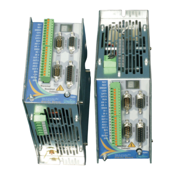
- Page 1 MANUAL Digital Servo Controller DS-205.4, DS403.4 EC Servo Motors AC Induction Motors DC-Servo Motors issue 1111-V6...
-
Page 2: Table Of Contents
DS 205.3 ; DS403.4 Contents Part 1 Hardware-Manual Contents Page Basis-Information Safety instractions General Application Contruction Technical data 8,9,10 Mechanical Installation Important instructions Dimension DS 400 Dimension Frontpanel Dimension Accessories Assembly Electrical Installation Important instructions Block diagram 17,18 Connection diagram 19,20 Connectors Mains connecting... - Page 3 DS 205.3 ; DS403.4 Blank page...
- Page 4 DS 205.3 ; DS403.4 Electronic devices are never fail-safe. Caution: High voltage DC 900V=. Electric shock hazard! Danger to personnel! DC-BUS discharge - time >4min This manual must be carefully read and understood by the professional prior to installation or start-up. Consult the manufacturer or the dealer if anything is unclear.
- Page 5 DS 205.3 ; DS403.4 The user must ensure: - that when the unit fails - when an operator error occurs, - when the controlling and control units fail, etc.. the drive homes to a safe operating state. Apart from that machines and installations must be provided with monitoring and safety systems independent from the unit.
-
Page 6: General
DS 205.3 ; DS403.4 A feature of the digital three-phase servo amplifier DS xxx and the brushless d.c. motor (synchro servomotor, EC motor) drive unit is that it is maintenance-free and has high control dynamics. The drive exhibits the known good control characteristics of d.c. drives without the disadvantages of carbon brush service times and the commutation limit. -
Page 7: Application
DS 205.3 ; DS403.4 Application in: All types of machines and installations up to a drive power of 1kW. Especially as 4Q- servo drives in feed axes, for highly dynamic acceleration and braking applications, for large control ranges, for high efficiency, for small motor dimensions, for an even and smooth travel. - Page 8 DS 205.3 ; DS403.4 Construction, characteristics: Cabinet-mounted device in an all-steel housing. In compliance with VDE/DIN and EU guidelines. (IP20, VGB4). Standard fully-digital regulation electronics. Power electronics from 5A ;3A (S1 - operation). Power input voltage 30V~ to 480V~. Independent 24V - chopper power supply unit for auxiliary voltages. DC decoupling between: the housing to all electrical parts auxiliary voltage connection to power unit and control electronics,...
-
Page 9: Corel Ventura
Basic - Information Power supply voltage DS205.4 1x oder 3x 30V~ bis 1x230V~ +10% 50/60 Hz Power supply voltage DS403.4 1x oder 3x 30V~ bis 1x480V~ +10% 50/60 Hz Auxiliary supply 24V= ± 10% / 2A Ripple voltage <10%, self-resttable fuse Data Dim. - Page 10 Basic - Information Ambient conditions Enclosure protection IP20, VGB4 Norms EN60204, Ambient temperature 0 bis +45 Maximum ambient temperature C to +60 C with power derating 2%/ Storage temperature C to +80 Humidity in operation Klasse F rel. humidity <85% ,no condensation ! Site altitude £...
- Page 11 Basic - Information...
- Page 12 DS 205.3 ; DS403.4 Important notes: Mounting surface blank metal, not varnished (surface EMC contact) Check device for mechanical damage. Mount only perfect devices. Cut all power prior to assembly. Insert shortening plug and attach warning signs at installations already electrically connected. Assembly permitted only by competent professionals.
-
Page 13: Dimension Ds 400
DS 205.3 ; DS403.4 Size 1 DS-205.4 to DS-403.4 Depth without connectors 190mm with connectors max. 250mm Screw for hex key M4x10 DIN 912... -
Page 14: Dimension Frontpanel
DS 205.3 ; DS403.4 Dimensions accessories EMC-Filter Type Spannung Strom Masse Gew. HxBxTmm F250V-B90-16 1x250 1x16 45x90x40 F400V-B51 1x400 35x51x40 Filter for stricter EMC - requirements. DC-BUS filters and input capacitors are incorporated in the device. Mount filter close to device. Motor choke Type Strom... -
Page 15: Dimension Accessories
DS 205.3 ; DS403.4 For good EMC values we recommend blank metal, unvarnished mounting bases. Good surface contact is achieved by the blank metal rear wall of the device. Lay signal lines and power cables in separate cable channels, cross them at right angles. (Spacial separation of interference coupling). -
Page 16: Assembly
DS 205.3 ; DS403.4... -
Page 17: Electrical Installation
Electrical Installation Important notes With reference to allocation of connections to the plug and terminal numbers the connection notes are binding.! All other notes on this subject are not binding. The input and output lines can be changed and supplemented to comply with electrical regulations and guidelines. -
Page 18: Block Diagram
Electrical Installation 27/28 29/30 GND24 GND24 AGND 9/10 BTB/RDY RUN/FRG IIST1A LMT1/END1 IIST2A LMT2/END2 DIN1 DIN2 GNDE DOUT1 DOUT2 DOUT3 AIN1+ AIN1- AIN2+ Uesp AIN2- OUT-AN Ballast RS232 9pol FAULT CAN-V+ CANH HPRES CANL 9pol-D CAN-GND PWM 6x & Feedback 15pol-D TMS 1-3 INC-OUT... - Page 19 Electrical Installation GND24 +15E GNDE IIST1A IIST2A Regen- resistor BAL- intern PWM-B UBMA Ballast FAULT EKURZ TEMP HPRES PWM 6x 3x PWM-High 3x PWM-Low KURZ digi 205-403...
-
Page 20: Connection Diagram
Electrical Installation Mains voltage maximum 3x230V+10% Auxiliary voltage 24V= +24V GND24 Line Detail X1-1 Page protection Safety circuit Ready Master GND24 connector Limit Auxiliary Control 26 28 switch voltage Mains filter MOTOR END1 Logic Limit input switch END2 Drive enable Enable AIN1+ RS IN... - Page 21 Electrical Installation Mains voltage maximum 3x480V+10% Auxiliary voltage 24V= +24V GND24 Line Detail X1-1 protection Page Safety circuit Master connector GND24 Control 26 28 Mains filter MOTOR END1 END2 AIN1+ RS IN AIN1- GNDE X1-2 DIN1 DIN2 DOUT1 DOUT2 bridge for int. regen AIN2+ resistor AIN2-...
-
Page 22: Emc
Electrical Installation CNC/SPS Input filter only with increased demands min 4ø double grounding X1:7 X1:8 X1:9 CAN- INC- analog setpoint Shield on the connector housing ext. regen resistor min 4ø 15 pin connector Shield on the double grounding connector housing Motor chokes min 4ø... - Page 23 Electrical Installation Encoder Ausgang CAN-BUS X9 Versorgung GND Kanal Kanal Kanal Kanal Kanal Kanal Versorgung +5V CAN-L CAN-H CAN-GND CAN-V+ Resolver SIN2 COS1 Temperatur REF1 Motor (GND) Temperatur REF2 Motor COS2 SIN1 Encoder X7 Rotorlage Versorgung GND Rotorlage Rotorlage Temperatur Motor Temperatur Motor...
- Page 24 Electrical Installation Connection to earthed mains or three-phase network. DS205.4 1x230V~ Do not, even briefly, exceed maximum maximal connected voltage of275V~. 1x 230V +10% Destruction hazard!! Device F1.x fuses F1 = FF safety fuses or semiconductor cutouts Power relais DS 205.3 Booster line filter for stricter EMC Mains filter requirements.
- Page 25 Electrical Installation Connection to the grounded AC-or three-phase system (TN-C-Mains). Unbalanced grounded and do not connect grounded systems only isolation transformer! Connection on the T-NC network Do not, even briefly, exceed maximum maximal 1x 480V +10% connected voltage of 528V~. Destruction hazard!! Device F1.x...
- Page 26 Electrical Installation Attention: In case of supply networks without PE conductor. Connection only via isolation transformer Connection on the TT network TT network Asymmetric three-or four-wire three-phase system with a direct ground. PE device on earth Transformer Transformer Filter Filter Connection on the IT network IT network Asymmetric three-or four-wire...
-
Page 27: Mains Connecting
Electrical Installation Inrush The initial inrush current is internally limited by an NTC resistor 10 times the rated current (about 2ms). The response is maintained between off and on again when a waiting time of 120sek is maintained. The NTC resistance is in the cooling power of the equipment fan. -
Page 28: Motor Connection
Electrical Installation Motor power connection Use only Unitek approved, electronically commutated synchronous motors (brushless DC motors, EC motors) with a resolver or an incremental encoder. See Appendix A (specific motor connection and parametrizing rules). DS 205-DS403 Motor-connector X3:8 X3:1 I-Ist2A X3:2 RS/IN MOTOR... -
Page 29: Regen Resistor
Electrical Installation Regenerative circuit The energy generated during braking is refed to the DC-BUS. The Elkos DC-Buses are able to store only a small amount of energy. The excess energy has to be converted into heat in the regenerative resistor. The internal resistor is designed for drives without flyweights. - Page 30 Electrical Installation Digital input Opto-input Digital input (IP65) X1:5 Limit switch 1 END1/LMT1 (X1:E) Input voltage X1:6 Limit switch 2 END2/LMT2 (X1:F) H-level (ON) +10 up to +30V X1:7 Enable FRG/RUN (X1:G) X1:11 Digital Input 1 DIN1 (X1:L) L-level (Off) <...
- Page 31 Electrical Installation Safety input RFE (Rotation enable) Warning! If the input of the enable or of the rotating field enable are switched off, the drive is free of torque. The drive could move if there is no mechanical brake or block provided.
- Page 32 Electrical Installation Digital logic outputs (open emitter) The logic outputs 1 to 3 are rated for 24V and 1A (short-time: 2A) Output voltage Digital output (IP65) On-level max. +24V X1:13 Digital output 1 DOUT1 (X1:N) X1:14 Digital output 2 DOUT2 (X1:O) Off-level <1V...
- Page 33 Electrical Installation Analog inputs +/- 10V 100k 1.5V +/- 1.36V analog inputs 100k 100nF Sollx REF150 100k DSxx/BAxx Input Plug Basic- Function Voltage Status Parameter AIN1+,AIN1- X1:8, X1:9 Speed setpoint +/-10V prog. AIN2+,AIN2- X1:15,X1:16 Current limit +/-10V prog. Characteristics Differential input AIN1+/AIN1- AIN2+/AIN2- Input resistance...
-
Page 34: Rs232
Electrical Installation RS 232: Via the serial PC RS232 interface the DS400 amplifier is programmed and operated for the start-up. The software is described in the DS software manual. The serial interface is galvanically coupled with the device - zero (GND) . Connector at PC T2OU Stecker am PC... -
Page 35: Can-Bus
Electrical Installation CAN-BUS The CAN-BUS is a digital connection to the CNC control. Optimum conditions are achieved with CNC controls and CAN components of LABOD electronic or CAN Open. Programming and operation by means of the control panel via the CAN-BUS. Interface complies with the standard ISO 11898. -
Page 36: Resolver
Electrical Installation Resolver - connection. Applicable only for DS xx-RS D-Stecker X7 The resolver is an absolute D-connector X7 Motor-connector measuring system for one motor Motor-Stecker DSxx/BAxx revolution. It is rugged and not Resolver sensitive to high motor temperatures. Its set-up is like a rotating transformer. -
Page 37: Encoder
Electrical Installation Encoder - connection. Applicable only for DS 4xx - IN Incremental encoders with 2 counting tracks and a zero track plus 3 rotor position tracks. Counting D-connector X7 tracks with push-pull output. D-Stecker X7 DS xx/BAxx Counting - input corresponds to RS485. -
Page 38: Sin-Cos
Electrical Installation SIN / COS Connection only for DS xx-SC Incremental encoder with 2 D-connector X7 analog sinusoidal counter D-Stecker X7 DS xx/BAxx tracks and 1 zero track plus 2 VCC +5V VCC +5V commutating tracks. Differential inputs 1Vss Max. counting frequency 500kHz Faktor The incremental encoder is... - Page 39 Electrical Installation Rotor position encoder - connection via a bl-tacho only for DS xx-bl 3 rotor position encoder signals (Hall sensors) for the commutation; with or without a brushless tacho. The rotor position encoder is galvanically connected with the D-connector X7 D-Stecker X7 Adapter DS xx/BAxx...
-
Page 40: X8 Encoder Out-In
Electrical Installation X8 TTL- Encoder output or input (2) The D connector X8 is connected as input or output (default). Output X8 pin 6 not connected or bridge toGND Input X8 pin 6 bridge to +5V (X8:1) VCC-CNT LBR 1 Inc-In D-connector X8 D-Stecker X8... - Page 41 Electrical Installation X8 as TTL Encoder output The encoder signals supplied by the motor (feedback) are available at the output of the D-connector X8 for the CNC control. The encoder output is internally isolated. The voltage is supplied via the encoder line from the CNC/PLC control. Voltage supply +5V ±0.2V.
-
Page 42: Led-Display
Electrical Installation LED displays on the Servo The state “normal” is signalled by a bright green seven-segment display + decimal point (display of the state). The state “fault” is signalled by a bright red fault LED and the seven-segment display indicates the error no. -
Page 43: Error List
Electrical Installation Error message on the Servo In case of an error the red LED ‘fault’ lights up and the green 7-segment display indicates the error number. Error list Display Description Error message on the address on the NDrive Servo Ox8f BADPARAS Parameter error... -
Page 44: Warning List
Electrical Installation Warnings The warning messages are displayed in the window ‘warnings’. Warning messages Warning message Warning Description ID-address display on the NDrive 0x8f Bit 16 Bit 17 Bit 18 Bit 19 Bit 20 POWERVOLTAGE Leistungsspannung zu klein oder fehlt Bit 21 MOTORTEMP Motortemperature >... -
Page 45: Options
Electrical Installation... -
Page 46: Guarantee
Electrical Installation Guarantee UNITEK guarantees that the device is free from material and production defects. Test results are recorded and archived with the serial number. The guarantee time begins from the time the device is shipped, and lasts one year. Unitek undertakes no guarantee for devices which have been modified for special applications.
Need help?
Do you have a question about the DS-205.4 and is the answer not in the manual?
Questions and answers