
Summary of Contents for Planet MB502
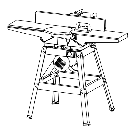
- Page 1 OWNER’S OPERATING MANUAL MB502 6” DELUXE JOINTER 带格式的 Please keep this instruction manual for future reference.
-
Page 2: Safety Rules
Keep work area well-lighted. 8. KEEP CHILDREN AND VISITORS AWAY. All children and visitors should be kept a safe distance from work areas. 9. MAKE WORKSHOP CHILDPROOF - with padlocks, master switches, or by removing starter keys. 1 MB502 6” Deluxe Jointer... - Page 3 23. NEVER LEAVE TOOL RUNNING UNATTENDED. TURN POWER OFF. Do not leave tool until it comes to a complete stop. 24. DRUGS, ALCOHOL, MEDICATION. Do not operate tool while under the influence of 2 MB502 6” Deluxe Jointer...
-
Page 4: Additional Safety Rules For Jointers
11. AVOID awkward operations and hand positions where a sudden slip could cause your hand to move into the cutterhead. 12. ALWAYS use hold-down/push blocks for jointing material less than 3 inches in height or planning material thinner than 3 inches. 3 MB502 6” Deluxe Jointer... - Page 5 The fence is square with the table and the depth of cut is approximately 1/8 inch. The workpiece is positioned on the jointer with the narrow edge of the workpiece on the infeed table and the major flat surface of the workpiece against the fence, as shown 4 MB502 6” Deluxe Jointer...
- Page 6 Fig.3. The workpiece is moved from the infeed table, across the cutterhead to the outfeed table establishing a flat surface on the workpiece. Always use push blocks when performing planning operations. Fig. 3 5 MB502 6” Deluxe Jointer...
-
Page 7: Unpacking And Cleaning
(do not use acetone, gasoline or lacquer thinner for this purpose). After cleaning cover the table surface with a good quality paste wax. Buff out the wax thoroughly to prevent it from rubbing into the workpieces. Fig. 4 Fig. 5 6 MB502 6” Deluxe Jointer... - Page 8 Round handle for infeed and outfeed table adjustment ASSEMBLY INSTRUCTIONS WARNING: FOR YOUR OWN SAFETY, DO NOT CONNECT THE JOINTER TO THE POWER SOURCE UNTIL THE JOINTER IS COMPLETELY ASSEMBLED AND YOU HAVE READ AND UNDERSTOOD THE ENTIRE OWNERS MANUAL. 7 MB502 6” Deluxe Jointer...
-
Page 9: Assembling Stand
2. Assemble dust chute (D) Fig. 7, to outfeed end of stand (C) as shown, using four 1/2” long carriage bolts (F), flat washers, and hex nuts. Only tighten hex nuts finger tight at this me. Fig. 7 8 MB502 6” Deluxe Jointer... -
Page 10: Assembling Jointer To Stand
(B) on the two top end braces. NOTE: Dust chute (C) is on outfeed end of jointer. Line up the three threaded holes on the bottom of the jointer with the three holes (A) and (B) in the stand end braces. Fig. 9 9 MB502 6” Deluxe Jointer... - Page 11 Assemble motor pulley (A) Fig. 11 to motor shaft with the hub of the pulley in the outer position as shown. Make sure key (B) in inserted in the keyway of the motor pulley and shaft. Fig. 11 10 MB502 6” Deluxe Jointer...
- Page 12 6. Replace cutterhead pulley guard Fig.12, which was removed in STEP 1. ASSEMBLING MOTOR PULLEY AND BELT GUARD Assemble the motor pulley and belt guard (A) Fig.13, to the jointer base using the four 1/2” long screws, and four lock washers. Fig. 13 11 MB502 6” Deluxe Jointer...
-
Page 13: Assembling Fence
(D) and washer (E). Fig.15 3. Thread fence locking handle assembly (F) Fig. 22, and flat washer (G) into hole (Z) Fig.21. Lock handle (F) Fig.22, is spring-loaded and can be repositioned by pulling out the 12 MB502 6” Deluxe Jointer... -
Page 14: Assembling Cutterhead Guard
(D) to provide tension on the spring before inserting post (B). Make certain the spring engages in the slot of the post. If spring tension is too much or too little, adjust the spring accordingly by removing the guard and rotating knob (D). Fig. 17 13 MB502 6” Deluxe Jointer... -
Page 15: Extension Cords
4. Check with a qualified electrician or service personnel if the grounding instructions are not completely understood or if in doubt as to whether the tool or outlet is properly grounded. 14 MB502 6” Deluxe Jointer... -
Page 16: Connecting Jointer To Power Source
Check with a qualified electrician or service personnel if the grounding instructions are not completely understood, or if in doubt as to whether the tool is properly grounded. 15 MB502 6” Deluxe Jointer... -
Page 17: Operating Controls And Adjustments
To move the outfeed table up of down, loosen lock screw Fig. 20, and turn hand knob (B). When the outfeed table is exactly level with the knives at their highest point of revolution, tighten lock screw (A). 16 MB502 6” Deluxe Jointer... - Page 18 5. Repeat these procedures for adjusting the remaining two knives if necessary. 6. If the knives are set too low, the result will be as shown in Fig. 21, and the finished 17 MB502 6” Deluxe Jointer...
- Page 19 8. As a final check, run a piece of work slowly over the knives for 6 to 8 inches. The wood should rest firmly on both tables as shown in Fig. 45, with no open spaces under the finished cut. 18 MB502 6” Deluxe Jointer...
-
Page 20: Adjusting Table Gibs
(A). As the fence is moved across the table, the rear cutterhead guard (B) covers and guards the cutterhead in back of the fence. NOTE: Lock handle (A) is spring-loaded and can be repositioned by pulling 19 MB502 6” Deluxe Jointer... - Page 21 10. If an adjustment is necessary loosen locknut (H) Fig. 54, and turn adjusting screw (J) until fence is tilted 45 degrees in. The tighten lock nut (H). ADJUSTING FENCE GUARDS 20 MB502 6” Deluxe Jointer...
-
Page 22: Removing, Replacing And Resetting Knives
(B) Fig. 57, by turning each screw counterclockwise just enough to hold the knife in position. Replace the remaining two knives in the same manner. NOTE: KNIVES MUST BE INSTALLED CORRECTLY AS SHOWN IN FIG. 21 MB502 6” Deluxe Jointer... - Page 23 (B) by turning them counterclockwise. 15. Adjust the remaining two knives in the same manner. WARNING: MAKE CERTAIN THAT ALL KNIVES ARE SECURELY FASTENED IN CUTTERHEAD BEFORE TURNING ON POWER. 16. Replace cutterhead guard. 22 MB502 6” Deluxe Jointer...
-
Page 24: Maintenance And Repairs
DURING OPERATION. OPERATION The following directions will give the beginner a start on jointer operations. Use scrap pieces of lumber to check settings and to get the feel of the operations before attempting regular work. 23 MB502 6” Deluxe Jointer... -
Page 25: Placement Of Hands During Feeding
Depth of cut should be the minimum required to obtain a straight edge. Hold the best face of the piece firmly against the fence throughout the feed as shown in Fig. 65. Maximum depth of cut should not be more than 1/8” in one pass. MB502 6” Deluxe Jointer... - Page 26 Fig. 65 DO NOT PERFORM JOINTING OPERATIONS ON MATERIAL SHORTER THAN 10 INCHES, NARROWER THAN 3/4 INCH, OR LESS THAN 1/2 INCH THICK (REFER TO FIG. 66). Fig. 66 MB502 6” Deluxe Jointer...
-
Page 27: Planing Or Surfacing
Fig. 68. If the bevel is laid out on the piece in such direction that this involves cutting against the grain, it will be better to tilt the fence to the right. MB502 6” Deluxe Jointer... -
Page 28: Taper Cuts
Fig. 68 TAPER CUTS One of the most useful jointer operations is cutting an edge to a taper. The method can be used on a wide variety of work. Tapered legs of furniture are a common example. Instead of laying the piece on the infeed table, lower the forward end of the work onto the outfeed table. -
Page 29: Planing Warped Pieces
Fig.70 illustrates using the Push Blocks properly. DO NOT PERFORM PLANING OPERATIONS ON MATERIAL SHORTET THAN 10 INCHES, NARROWER THAN 3/4 INCH, WIDER THAN 6 INCHES, OR LESS THAN 1/2 INCH THICK (REFER TO FIG. 71). MB502 6” Deluxe Jointer... -
Page 30: Direction Of Grain
Avoid feeding work into the jointer against the grain as shown in Fig. 72. The result will be chipped and splintered edges. Feed with the grain as shown in Fig. 73, to obtain a smooth surface. MB502 6” Deluxe Jointer... - Page 31 Fig. 72 Fig. 73 MB502 6” Deluxe Jointer...
- Page 32 MB502 6” Deluxe Jointer...
- Page 33 Screw Long Lower End Brace Cutterhaed Guard Long Side Brace Adjusting Shaft Cable Clamp Upper Cover Switch Cover Screw Cable Screw Plug Base Dust Chute Locking Washer Dust Chute Label Switch Cover Plate Screw Bolt Switch MB502 6” Deluxe Jointer...
Need help?
Do you have a question about the MB502 and is the answer not in the manual?
Questions and answers