Advertisement
Table of Contents
Advertisement
Table of Contents

Summary of Contents for DOF EDGE
-
Page 2: Table Of Contents
Table of Contents Note Check the Contents Scanner Parts Plates Connect the Scanner System Requirement Software Installation After Installation 9 - 10 Select Language Calibration Mouse Motion Icons 14 - 18 Basic Scan Sequence 19 - 30 Our Office Locations... -
Page 3: Note
10 secondes. Le programme de balayage fonctionne après avoir fini le préchauffage.) • Do not use USB WiFi adapters along with the Edge scanner. In order to obtain the maximum performance, Edge uses the full USB bandwidth. Using USB WiFi adapters may result in scan failures. -
Page 4: Check The Contents
Check the Contents Plates Cables & Gender Accessory Edge 3D Scanner Edge 3D Scanner Plates - Base Plates (2qty), Multi-Die Plate (1qty), Calibration Plate (1qty), Gum Plates (2qty), Zig Block Plate (1qty), Articulator Plate (1qty) Cables & Gender - Power Cable (1qty) Accessory –... -
Page 5: Scanner Parts
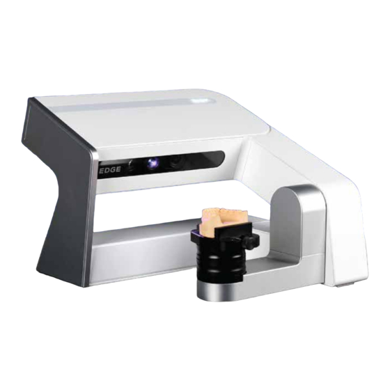
Scanner Parts Camera Projector Camera USB Cable Switch Power Connector... -
Page 6: Plates
Plates Basic Plates Base Plate Calibration Plate Multi-Die Plate Gum Plate Zig Block Plate Articulator Plate Optional Plate Transfer Plate A for Artex Transfer Plate S for KaVo and SAM Transfer Plate B for Bio-Art * Place Transfer Plates on top of a Base Plate on the scanning platform. All-in-One Plate Impression Plate &... -
Page 7: Connect The Scanner
You are highly recommended using HP800G2 desk top PC provided by DOF. (En cas de PC monté, il peut se produire un problème au niveau de la compatibilité et DOF ne prend pas tel problème en charge. On recommande d’utiliser HP 800 G2 Desktop PC offert par le siège social de DOF.) -
Page 8: Software Installation
Software Installation Run the ScanApp SW locating at DOF USB from the accessory box or download the latest ScanApp SW from the link you have obtained from your dealer/reseller. Install the software. Follow the wizard to successfully install the ScanApp SW. -
Page 9: After Installation
Check if both of the software is installed properly. Run the ScanApp for the first time. Press exocad icon. Opens DOF Start. Helps to choose desired dental CAD platform. Directs straight to Orthodontic Scan. Prompts dental DB selection. - Page 10 You can choose notation system. (Notation or Universal) You will be asked to specify the exocad DentalDB.exe is located. DentalDB.exe is usually located under the exocad-DentalCAD-versionnumber/ DentalDB/bin/ folder. After DentalDB is added, press run.
-
Page 11: Select Language
Select Language Run the ScanApp. ScanApp icon will be appeared at the hidden icon taskbar. Right click the ScanApp icon and click “Information” option to change the language of the program. Select your language. Available languages: Korean, English, German, Spanish, French, Italian, Japanese, Russian, Chinese, Portuguese... -
Page 12: Calibration
Calibration Make sure your scanner is connected and power is on. From the ScanApp application, click Press Start after placing calibration plate. Place the two “Base Plates” on the scanning platform and then place the “Calibration Plate” on top of it. It will take from 5 minutes to 10 minutes depending on the computer performance. -
Page 13: Mouse Motion
Mouse Motion Mouse Button Motion Explanation Click Select Left Hold and Drag Select scan areas Hold and Drag Rotate the view Right Hold and Drag Move the view Right & Left Scroll Up Zoom in Scroll Down Zoom out Scroll Wheel Hold and Drag Move the view... -
Page 14: Icons
Icons Pre Setting Calibrate Save – Enables one to start scanning from where it ended. Current Project – Indicates what types of restoration will be fabricated. Reload - Reloads the updated data of the Job Definition at exocad Manual Mode – Allows to freely jump to desired scanning step Open Project Folder - Loads dental project Plan –... - Page 15 Upper Base Lower Base Gingiva Scan Abutment Face Bow Upper Interproximal Lower Interproximal Upper Situ Inner Situ Upper Impression Lower Impression Quadrant Arch Upper Quadrant Arch Lower Bite Registration...
- Page 16 Camera Dark - Incremental adjustment of brightness. Bright – Incremental adjustment of brightness. Auto Exposure Cancel Scan Scan Rescan - Automatically deletes current scanned data for another attempt. Home - Repositions rotating arm/stage to default degree. Preview - Allows users to check how much models will be exposed to camera exposure.
- Page 17 Match Previous Model Auto Align - Automatically allocates 3 dots among scanned data. Match - Helps to join manually allocated data. Next Model Post Setting Match – Combines scanned data. Build – Prepares rendering process for designing. Trim – Removes unnecessary data for optimum data process.
- Page 18 View Front View – Upper model base. Rear View – Lower model base. Left View – Left buccal side. Right View – Right buccal side. Top View – Facial side. Bottom View – Lingual side. Fit to Window Wireframe Texture On / Off...
-
Page 19: Basic Scan Sequence
Basic Scan Sequence Open Dental DB. Define and select Customer, Job, and Technician. Define your dental indications from the tooth diagram on the right. Define Scan Model type. Click “Save” button and you will see “Scan with ScanApp” button being active. - Page 20 Click the “ScanApp” button to run the scanning application. Your “Scan Wizard” will guide you through the scanning process. The first wizard step lets you choose different scanning options.
- Page 21 Place a model on the scan platform. The model should be placed as the incisor is faced towards the inside of the scanner. From the “Camera View” windows, check if the model is in the camera view. You can adjust the height of the model by removing or adding “Scan Plates” from the scan platform.
- Page 22 Pre-scanning Place an adjacent model in the platform and click “Scan” The scanner will obtain the overall shape of your adjacent model. A first quick scanning will be performed and this will capture the overall shape of your model. A detailed scanning of your prepped dies will be done during later steps, so you do not need to capture everything at this stage.
- Page 23 Supplemental Scanning After each batch of scanning, there are two ways to fill in more data to your scan. Rotate and position the 3D data so that you are able to see the missing area. - Drag desired additional scan area and release the mouse button for scanning. - Click “Scan Additional”...
- Page 24 Prep Teeth Scanning (Detail Scanning) In the Prep Teeth Scanning step, you will be asked to take out all adjacent teeth from the model, only leaving the prepped dies on the model. Set the brightness level so that you have the optimal brightness level for the prepped dies. Depending on the indication complexity, you will need to repeat the “Prep Teeth Scanning”...
- Page 25 Antagonist Scan Place an antagonist model in the platform and click “Scan” The scanner will obtain the overall shape of your antagonist model. You will have another chance to do “Supplemental Scan” if you need to fill in incomplete areas.
- Page 26 Occlusion Scan Place an occlusion relationship model in the platform and click “Scan” Upper jaw is usually placed on top, but if the lower jaw is placed on top, check the box. The scanner will obtain the overall shape of your occlusion relationship model.
- Page 27 You have two options to scan occlusion relationship. By stone model/simple articulators: Simply place the articulated upper and lower jaws on the scan platform. The camera axis will move up and down to capture your occlusion relationship. By fully adjusting articulators: Remove all “Scan Plates”...
- Page 28 • Auto Alignment If the two sets of scan data are in similar directions and have relatively unique shape, then most likely your data will be matched automatically. This can be checked from the right section of “Alignment Window”. If the two different colored data are combined in the right positions, then the alignment had been successful.
- Page 29 Data edit and confirmation. You can edit the last data before the final data confirmation. It can be helpful to reduce the merging time. Click left mouse button and select unnecessary part for optimum data process. Then click “Trim Inside”. You can also remove outside of rectangle area by clicking “Trim Outside“.
- Page 30 You can adjust file size and resolution of scanned data. Click to get the final data. Fill out the holes by clicking Even after you get the final data, you may edit the data by clicking After you confirm the final data, click to save the data and proceed to the CAD design program by clicking...
-
Page 31: Our Office Locations
607 S. Euclid St. Fullerton, CA 92832 USA • DOF China Office info@doflab.cn +86 755-2331-9063 1620, Rongchao-binhai Building A, Haixiu Rd, Baoan District, Shenzhen, China 广东省深圳市宝安区海秀路荣超滨海大厦A座1620室 • DOF Germany Office info@doflab.com +49 6196-7765675 Ludwig-Erhard-Str. 30-34, 65760, Eschborn, Germany Copyright © 2018 DOF Inc. All rights reserved.
Need help?
Do you have a question about the EDGE and is the answer not in the manual?
Questions and answers