
Summary of Contents for Alfa Laval Alfie
- Page 1 Alfa Laval Alfie Cleaning system for liquids Instruction Manual Product No.: 9016086-80, -81 9016092-80, -81 Book No.: 9017117-02 Rev. 8...
- Page 2 Telephone: +46 8 530 650 00 Telefax: +46 8 530 310 40 © Alfa Laval Tumba AB 05-2016 Original instruction This publication or any part there of may not be reproduced or transmitted by any process or means without prior written permission of...
-
Page 3: Table Of Contents
Contents Safety instructions Application Machine plates Description of main parts System overview Separator Pump Control unit Collecting tank Working principle of the separator Control Cabinet Operator panel Connection for correct voltage Alarm light pattern Alarm table Operating instructions Before first start Before normal start Start Operation... - Page 4 Pump does not start Pump stops Separator stops Noise Separator vibrates No flow from pump Flow too low No flow either through clean oil outlet or through drain to collecting tank 8.10 Some liquid escaping through drain outlet to collecting tank 8.11 Oil flow through drain outlet to collecting tank only...
- Page 5 10.2 Declaration 11 Lifting instruction 11.1 Cleaning unit 12 Diagrams 12.1 Electrical system...
-
Page 7: Safety Instructions
Ensure that personnel are competent and have sufficient knowledge of maintenance and operation. • Use only Alfa Laval genuine spare parts and the special tools supplied. Electrocution risk Switch off the power supply and remove the electric cable from the socket before opening the... - Page 8 1 Safety instructions Disintegration hazard The separator is supplied with a safety yoke and a magnetic safety switch. Modifications to the machine which put the safety devices out of operation can lead to serious injury or damage. stop If excessive vibrations occur, the separator.
-
Page 9: Application
2 Application The Alfa Laval Alfie 500 cleaning system is restricted to the removal of solids and oil from liquids with a temperature range between +15 and +70 °C. Disintegration hazard The cleaning system must not be operated in an... - Page 10 2 Application...
-
Page 11: Machine Plates
3 Machine plates The cleaning unit has two different machine plates. One for the separator only One for the complete unit G1101911 When ordering spare parts for the When ordering spare parts for the cleaning unit (except the separator) separator itself, please specify the please specify the article and serial type, product and serial numbers numbers stamped on the machine... - Page 12 H. Serial No.: D. Direction of rotation: Enclosure: E. Supply voltage: Article No. Serial No./Year Manufacturer Alfa Laval - Krakow Service enquiries www.alfalaval.com G1102721 Example of machine plate (complete unit) A. Article No. B. Serial No. C. Manufacturing Year Note that the illustrations are examples of a machine plates.
-
Page 13: Description Of Main Parts
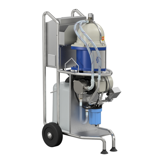
4 Description of main parts System overview The Alfa Laval Alfie 500 cleaning system consists of the following parts (numbered in process order): Suction device Feed inlet with adjustable height setting. For tanks with a depth min. 100 mm. Hoses For in- and outlet of feed between the cleaning unit and the liquid tank. - Page 14 4 Description of main parts Motorised regulating valve For maintaining the correct counter pressure in the outlet line (ca. 100 - 180 kPa). The valve is regulated by the control unit (9). Collecting tank (20 litres) Collects the oil separated out from the liquid. The tank stands on a support under the separator which is held in its upper position by a spring with adjustable tension (••).
- Page 15 4 Description of main parts ∗ ∗∗ G1102011 A suction device of bellows type can preferably be used in shallow tanks (55-100 mm).
-
Page 16: Separator
4 Description of main parts Separator The separator has a bowl hood interlock (3) over the hood (2) and connection housing (1). A magnet (4) in contact with a safety switch indicates if the yoke is in correct position. If not, no power is supplied to the motor. -
Page 17: Collecting Tank
4 Description of main parts Collecting tank The tank stands on a support under the separator which is held in its upper position by a spring with adjustable tension. The spring can be adjusted by the handle (1) on the underside of the support. When the collecting tank is nearly full the weight will overcome the spring tension and a limit switch is actuated. - Page 18 4 Description of main parts...
-
Page 19: Working Principle Of The Separator
5 Working principle of the separator Dirty liquid continuously enters at (A) and flows into the bowl (1). The bowl rotates at high speed generating powerful centrifugal forces. As the liquid rotates with the bowl, the liquid (heavy phase) and solid particles moves towards the periphery of the bowl. The particles (2) are deposited on the bowl wall, while the cleaned liquid enters the channels (3) and leaves the bowl (B) at a constant pressure. - Page 20 5 Working principle of the separator...
-
Page 21: Control Cabinet
6 Control Cabinet The operator panel is a 4" touch screen placed on top of the control cabinet. Do not use metal or any sharp objects to operate the panel. A stylus pen or similar however, can be used. Inside the control cabinet there are two frequency converters for regulating the speed of the separator and the pump, a 24VDC power supply and a PLC. - Page 22 6 Control Cabinet Control bar The control bar is always visible at the bottom of the screen. G1101211 Start, Stop and Standby buttons are blue when they are accessible, and grey when they are not. When an operating mode is active the corresponding button is circled in green.
- Page 23 6 Control Cabinet Tiles The startup screen contains three tiles, each representing a sub-equipment of the unit. When a sub-equipment is running the corresponding tile will be circled green. G1113811 Tapping a tile will display an overview of all devices within that sub-equipment. On the left hand side there is a status row for the sub-equipment and if applicable, setpoints for the devices and control functions for that subequipment.
- Page 24 6 Control Cabinet Separator The Separator screen shows the separator motor, the bowl hood interlock and the tank limit switch. A trip counter for batch running time is available. G1113831 Pressure control The Pressure control screen shows the pressure sensor and the pressure regulation valve. Pressure set-point can be changed from here.
- Page 25 From there the operator is given access to the following screens (starting on the top left hand side): Parameters Configuration of the system. Only possible to change values when logged in as Administrator. Administrator access level is only for Alfa Laval service engineers. Alarm history A list of all past alarms System time Set system time so correct time stamps are made in the alarm list.
- Page 26 6 Control Cabinet Alarm list The Alarm list shows all active and all unacknowledged alarms. It is always accessible from the Control bar. G1113861 Alarms can be for operator information only but in most cases it also forces the unit to another operating mode. See ‘‘6.4 Alarm table” on page 33.
-
Page 27: Connection For Correct Voltage
6 Control Cabinet Connection for correct voltage If the power supply is equipped with an ELCB (Earth Leakage Circuit Breaker) make sure that it is of industrial type that allows higher (30mA at 230 V) leakage current. If the cleaning unit should be connected to other voltage than 230 V, the unit should be equipped with a transformer (1). -
Page 28: Alarm Light Pattern
6 Control Cabinet Alarm light pattern - In STOP when separator is in standstill - In PRODUCTION Steady shine - During START - If an active alarm that has been acknowledged exists - During STOP as long as separator is not in standstill Blinking (0.5s on, 0.5s off) - When feed pump speed is boosted (Startup... -
Page 29: Alarm Table
6 Control Cabinet Alarm table Alarm Alarm delay Description Action A001 Too low counter Low counter pressure. pressure 8.3 Pump stops on page A002 Too low startup Startup pressure pressure. 8.3 Pump stops on page A003 Signal out of range on Pressure sensor out of range Check sensor cable. - Page 30 6 Control Cabinet...
-
Page 31: Operating Instructions
7 Operating instructions Before first start Check that the unit is wired for correct voltage, 6.2 Connection for correct voltage on page Before normal start If the strainer (pos. 7) has been cleaned/emptied, check that filter housing is filled with liquid. If the cleaning unit has been out of operation for a longer period, the pump impeller should be greased before use to receive optimal suction ability. - Page 32 7 Operating instructions G1102311 1a. Suction device for deeper tanks (min. 100 mm) 4. Hood screws (3 pcs) 1b. Suction device for shallow tanks (55 - 100 mm) 5. Knob 2. Feed inlet 6. Bowl hood interlock 3. Feed outlet 7.
- Page 33 7 Operating instructions 2. When there is no alarm active and unacknowledged the operator can tap the Start button and the cleaning unit will start. The separator starts. When it has reached full speed the feed pump starts. The control system waits for the pressure to rise.
- Page 34 7 Operating instructions If using the suction device with bellows (option), check that the top is located just under the surface in the tank so that the surface layer is sucked into the bellows. The setting is self-adjusted. G0986981 4. Increase the counter pressure slowly until a small stream of oil/ liquid is observed coming from the oil outlet (1).
-
Page 35: Operation
7 Operating instructions Operation 1. Check the cleaning unit for correct operation (correct flow from outlet, counter pressure and vibration). This is especially important the first time the cleaning unit is run after installation or dismantling and assembly. 2. When the collecting tank is nearly full, the pump is stopped automatically and the lamp on the g1106311... - Page 36 7 Operating instructions When the separator has nearly stopped rotating (within two minutes), the liquid content of the bowl will be drained by gravity into the collecting tank. If the position of the tank level is higher than the inlet/outlet of the separator, there is a risk that liquid may be siphoned from the tank and drained via the separator into the collecting tank.
-
Page 37: Trouble Shooting
8 Trouble shooting Cleaning system/separator does not start or stops shortly after start Possible cause Action No power supplied Check the mains switch, fuses and supply line Bowl hood interlock is not in correct position Position the interlock correctly Defective magnetic switch indicating the Check that the switch opens and closes when position of the bowl hood interlock interlock is moved up and down... -
Page 38: Separator Stops
8 Trouble shooting Possible cause Action Voltage protection on frequency card trips Check the voltage. If unstable voltage, connect because of too low/high voltage or voltage a transformer. spikes Remedy - replace Defective motor/frequency converter Separator stops Possible cause Action Bowl hood interlock out of correct position Reposition the interlock Overload due to clogged disc stack... -
Page 39: Separator Vibrates
8 Trouble shooting Separator vibrates Disintegration hazard STOP If excessive vibrations occur, the separator Possible cause Action Bowl out of balance due to: Dismantle and clean the separator bowl. Be • Insufficient or incorrect cleaning sure that the separator is assembled correctly. (sludge in disc stack) •... -
Page 40: Flow Too Low
8 Trouble shooting Flow too low Possible cause Action Impeller in pump worn or broken Replace impeller, See 9.6 Replacing the impeller and mechanical seal for pump on page Reduce the counter pressure with the regulating Counter pressure at outlet too high valve (100 - 180 kPa is recommended) Leakage caused by incorrect assembly •... -
Page 41: Some Liquid Escaping Through Drain Outlet To Collecting Tank
8 Trouble shooting 8.10 Some liquid escaping through drain outlet to collecting tank Possible cause Action • Reduce the counter pressure with the Counter pressure at outlet too high regulating valve (100 - 180 kPa is recommended) • Reduce the flow by adjusting the screw fitted in pump Leaking O-rings in separator Replace O-rings... -
Page 42: Insuficient Separation Result
8 Trouble shooting 8.14 Insuficient separation result Possible cause Action The suction device in liquid tank lays too Adjust the height. See description in chapter high 7.3 Start on page 31 Separator disc stack clogged Clean separator bowl and disc stack Increase the counter pressure until oil is observed to be discharged from the oil outlet, The counter pressure is too low... -
Page 43: Maintenance
9 Maintenance Entrapment hazard Switch off the power supply, remove the electric cables from the sockets and make sure that rotating parts complete standstill have come to a before starting any dismantling work. Never use cleaning agents with a pH below 6 or above 9 as they can damage the metal surfaces. -
Page 44: Once Per Month
9 Maintenance Control of sludge content Dismantle the separator and measure the thickness (A) of the sludge collected on the bowl wall. The thickness should never exceed 10 mm. If the interval between bowl cleaning is too long, this can result in a sludge cake that is hard and difficult to remove. -
Page 45: Every Second Year
9 Maintenance Check the condition of discs in the bowl, replace if necessary. Fit new vibration dampers. To get access to the dampers, only remove the three screws and washers shown in illustration 10 on page 52. Inspect the stop flanges of the dampers for possible damage and replace the stop flanges with new ones if necessary. -
Page 46: Cleaning Of Bowl
9 Maintenance 9.5.2 Cleaning of bowl Comments to illustrations following. Illustration 4: Before dismantling the separator, wait until the rotating parts have come to a complete standstill, which will take up to two minutes. To be sure, open the front cover and check that the rotation of the electric motor shaft has stopped. - Page 47 9 Maintenance Dismantling G04491c1 *See comments on opposite page...
- Page 48 9 Maintenance Comments to illustrations on opposite page. Illustration 16: When fitting the bowl shell, press firmly downwards with both hands to overcome the resistance from the O-ring fitted on the bowl bottom. A “clicking” sound will be heard. G0912141 Illustration 17: If the level ring (1) and O-ring (2) have been removed, first fit the level ring and then the O-ring...
- Page 49 9 Maintenance Illustration 22: before Always screw home the knob fitted on the connecting housing tightening the screws shown in illustration 23. Otherwise there is a risk that the pin inside the connecting housing could break. Assembly <0.5 mm G0449281 *See comments above and on opposite page.
-
Page 50: Replacement Of O-Rings
9 Maintenance 9.5.3 Replacement of O-rings Comments to illustrations on opposite page. Illustration 5: Take care of the washer. Illustration 13: Check that the washer is fitted. Otherwise there is a risk that the bowl will not make firm contact with the spindle. - Page 51 9 Maintenance First dismantle the separator bowl as described in 9.5.2 Cleaning of bowl on page G05191j1 *See comments on opposite page.
-
Page 52: Replacement Of Motor Bearings
9 Maintenance 9.5.4 Replacement of motor bearings First dismantle the separator bowl as described in 9.5.2 Cleaning of bowl on page G0449461... - Page 53 9 Maintenance G0449671...
- Page 54 9 Maintenance G0449681...
-
Page 55: Replacing The Impeller And Mechanical Seal For Pump
9 Maintenance Replacing the impeller and mechanical seal for pump G09869a1 1. Screw cap 6. Motor flange 11. Washer 7. Shaft 12. Screw 2. Cover 3. Impeller 8. Screw stud 13. Washer 4. Pump body 9. O-ring 14. Lock screw 10. - Page 56 9 Maintenance Remove the impeller (3) from the pump body (4) by using suitable pliers or two levers. Take care not to damage the pump body. If replacing the mechanical seal, separate G09869b1 the pump body from the flange (6). Check for wear inside the pump body.
-
Page 57: Technical Data
10 Technical data 10.1 Technical data, system Denomination: Alfa Laval Alfie 500 Use is restricted to removal of solids and oil from water-based liquid with the following Application: specifications. Water-based liquid Process media: Technical design pH value: 6 – 9 Separation temperature: +15 –... -
Page 58: Declaration
The technical construction file for the machinery is compiled and retained by the authorized person Hans Thomasson within the Product Centre for High Speed Separator sytems, Alfa Laval Tumba AB, SE-14780 Tumba Sweden. Signed for and on behalf of: ...................... -
Page 59: Lifting Instruction
11 Lifting instruction 11.1 Cleaning unit Attach two lifting straps (1) to the lifting hooks. The distance between the lifting hooks and crane hook should be min. 1 metre (A). Weight of unit is approx. 60 kg. Entrapment hazard Only attach the lifting straps to the two lifting hooks when lifting the cleaning unit. - Page 60 11 Lifting instruction...
-
Page 61: Diagrams
12 Diagrams 12.1 Electrical system Alfa Laval ref. 9014733 Rev. 7... - Page 62 Alfa Laval Tumba AB C:\Documents and Settings\SETUGNH\My Documents\My Pictures\alfalaval.bmp Company / customer Project description Alfie/Emmie Main supply 230V AC (100/110/120VAC with optional transformer) Control voltage 24V DC Manufacturer (company) Alfa Laval Tumba AB Drawing number 9014733 Created on 2014-04-01 SETUTBL...
- Page 63 Created date Created by Revised by Project Title Location Page Revision Revised date Page 2014-04-01 SETUTBL SETUTBL 2015-03-26 Alfie/Emmie Cable-connection diagram 1 W001 W002 W003 W201 Department Approved date Approved by Mounting Latest Revision Document No. Next page 9014733 2015-10-23 SETUNLN...
- Page 64 PE bar. Created date Created by Revised by Project Title Location Page Revision Revised date Page 2014-04-01 SETUAKL SETUAKL 2015-10-07 Alfie/Emmie Cable-connection diagram W202 W401 W402 Department Approved date Approved by Mounting Latest Revision Document No. Next page 9014733 2015-10-23 SETUNLN...
- Page 65 Note: All signal cables should be a Signal Shielded Cable with the shield properly connected to earth as shown in the electrical drawings. 1) Cable not included in Alfa Laval delivery 2) Cable type and size according to VFD/motor specification For power cables, armour must be connected to the earth bar.
- Page 66 1mm² Orange Created date Created by Revised by Project Title Location Page Revision Revised date Page 2014-04-01 SETUTBL SETUTBL =9014733 2014-09-05 Alfie/Emmie Wiring table Department Approved date Approved by Mounting Latest Revision Document No. Next page 9014733 2015-10-23 SETUNLN +CP01...
- Page 67 24 25 Created date Created by Revised by Project Title Location Page Revision Revised date Page 2014-04-01 SETUTBL SETUAKL =9014733 2015-10-23 Alfie/Emmie Control cabinet assembly Department Approved date Approved by Mounting Latest Revision Document No. Next page 9014733 2015-10-23 SETUNLN +CP01...
- Page 68 All meassurements in mm Created date Created by Revised by Project Title Location Page Revision Revised date Page 2014-04-01 SETUTBL SETUAKL =9014733 2015-10-23 Alfie/Emmie Control cabinet assembly Department Approved date Approved by Mounting Latest Revision Document No. Next page 9014733 2015-10-23 SETUNLN +CP01...
- Page 69 Ø16 Ø20 Created date Created by Revised by Project Title Location Page Revision Revised date Page 2014-04-01 SETUTBL SETUTBL =9014733 2014-09-05 Alfie/Emmie Control cabinet assembly Department Approved date Approved by Mounting Latest Revision Document No. Next page 9014733 2015-10-23 SETUNLN +CP01...
- Page 70 X400 X401 Created date Created by Revised by Project Title Location Page Revision Revised date Page 2014-04-01 SETUTBL SETUTBL =9014733 2015-03-26 Alfie/Emmie Terminal assembly Department Approved date Approved by Mounting Latest Revision Document No. Next page 9014733 2015-10-23 SETUNLN +CP01...
- Page 71 Note : A1-X1 to A1-X3 are integrated on CPU. Created date Created by Revised by Project Title Location Page Revision Revised date Page 2014-04-01 SETUTBL SETUTBL =9014733 2015-01-14 Alfie/Emmie PLC Assembly Department Approved date Approved by Mounting Latest Revision Document No. Next page 9014733 2015-10-23 SETUNLN +CP01...
- Page 72 PLUS MINUS Created date Created by Revised by Project Title Location Page Revision Revised date Page 2014-04-01 SETUTBL SETUAKL =9014733 2015-10-23 Alfie/Emmie 230VAC 24VDC Department Approved date Approved by Mounting Latest Revision Document No. Next page 9014733 2015-10-23 SETUNLN +CP01...
- Page 73 EMC cable gland +Field Separator Created date Created by Revised by Project Title Location Page Revision Revised date Page 2014-04-01 SETUTBL SETUTBL =9014733 2015-01-13 Alfie/Emmie Separator Department Approved date Approved by Mounting Latest Revision Document No. Next page 9014733 2015-10-23 SETUNLN +CP01...
- Page 74 EMC cable gland +Field Pump Created date Created by Revised by Project Title Location Page Revision Revised date Page 2014-04-01 SETUTBL SETUTBL =9014733 2014-12-01 Alfie/Emmie Pump Department Approved date Approved by Mounting Latest Revision Document No. Next page 9014733 2015-10-23 SETUNLN +CP01...
- Page 75 OP Created date Created by Revised by Project Title Location Page Revision Revised date Page 2014-04-01 SETUTBL SETUTBL =9014733 2015-03-24 Alfie/Emmie HMI Panels Department Approved date Approved by Mounting Latest Revision Document No. Next page 9014733 2015-10-23 SETUNLN +CP01...
- Page 76 X20CP1301 Created date Created by Revised by Project Title Location Page Revision Revised date Page 2014-04-01 SETUTBL SETUTBL =9014733 2014-09-05 Alfie/Emmie A1 - CPU Department Approved date Approved by Mounting Latest Revision Document No. Next page 9014733 2015-10-23 SETUNLN +CP01...
- Page 77 Created date Created by Revised by Project Title Location Page Revision Revised date Page 2014-04-01 SETUTBL SETUTBL =9014733 2015-03-26 Alfie/Emmie X1 - Inputs Department Approved date Approved by Mounting Latest Revision Document No. Next page 9014733 2015-10-23 SETUNLN +CP01...
- Page 78 Fault Created date Created by Revised by Project Title Location Page Revision Revised date Page 2014-04-01 SETUTBL SETUTBL =9014733 2015-03-26 Alfie/Emmie X2 - Inputs Department Approved date Approved by Mounting Latest Revision Document No. Next page 9014733 2015-10-23 SETUNLN +CP01...
- Page 79 24VDC Max 0.5A Created date Created by Revised by Project Title Location Page Revision Revised date Page 2014-04-01 SETUTBL SETUTBL =9014733 2015-03-24 Alfie/Emmie X3 - Outputs Department Approved date Approved by Mounting Latest Revision Document No. Next page 9014733 2015-10-23 SETUNLN +CP01...
- Page 80 Created date Created by Revised by Project Title Location Page Revision Revised date Page 2014-04-01 SETUTBL SETUTBL =9014733 2015-03-26 Alfie/Emmie A2 - Analog outputs Department Approved date Approved by Mounting Latest Revision Document No. Next page 9014733 2015-10-23 SETUNLN +CP01...
Need help?
Do you have a question about the Alfie and is the answer not in the manual?
Questions and answers