Table of Contents
Advertisement
Advertisement
Table of Contents

Summary of Contents for Acra 1440GWI
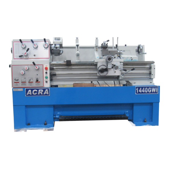
- Page 1 OPERATION MANUAL PRECISION GEAR HEAD LATHE MODEL:1440GWI...
-
Page 2: Warnings
13. Keep children and visitors away. All WARNING visitors should be kept a safe distance from Read and understand the entire contents of the work area. this manual before attempting set-up or operation of this lathe. 14. Make the workshop child proof. Use padlocks, master switches, and remove 1. -
Page 3: Specifications
Specifications: Series Number ......................... Capacities: Swing Over Bed ......................356mm(14〃) Swing Over Cross Slide ..................210mm (8-1/4〃) Swing Through Gap ....................506mm(20〃) Length of Gap....................….238mm(9-3/8〃) Distance between Centers..............…....1000mm (40〃) Headstock: Hole through Spindle.....................φ 40mm (1-1/2〃) Spindle Nose..........................D1-4 Spindle Taper Nose........................MT-5 Spindle Taper Adapter........................ MT-3 Spindle Bearing Type ..................Taper Roller Bearing Number of Spindle Speeds ...................... -
Page 4: Table Of Contents
Miscellaneous: Steady Rest Capacity..............φ 6mm—φ 95mm (1/4〃--3-3/4〃) Follow Rest Capacity..............φ 6mm—φ 69mm (1/4〃-2-3/4〃) Length of Bed......................1378mm(54-1/4〃) Width of Bed..…....................266mm (10-1/2〃) Height of Bed......................324mm(12-3/4〃) Overall Dimensions..............1924mmL x 750mmW x 1200mmH Main Motor....................……….4HP, 3Ph, 380V Net Weight (approx.)....................960kg(2112ibs) Shipping Weight (approx.)..................1090kg(2398ibs) Table of Contents: Warnings............................ -
Page 5: Contents Of The Shipping Container
WARNING Read and understand the entire contents of this manual before attempting set-up or operation! Failure to comply may cause serious injury! Contents of the Shipping Container 1 Lathe 1 Steady Rest 1 Follow Rest φ 160mm(6 〃 )Three Jaw Chuck w/ Top Reversing Jaws (Direct Mount) 1 200mm(8〃)Four Jaw Chuck with Back plate 1 300mm(12〃)Face Plate (strapped to container... -
Page 6: Uncrating And Clean-Up
Uncrating and Clean-Up Finish removing the wooden crate from around the lathe. Unbolt the lathe from the shipping crate bottom. Choose a location for the lathe that is dry, has good lighting, and has enough room to service the lathe on all four sides. Do not lift by spindle. -
Page 7: Chuck Preparation
Chuck Preparation (Three Jaw) WARNING Read and understand all the directions for chuck preparation! Failure to comply may cause serious injury and/or damage to the lathe! Note: Before removing the chuck from the spindle, place a way board across the bed ways under the chuck. -
Page 8: Lubrication
Lubrication CAUTION Lathe must be serviced at all lubrication points and all reservoirs filled to operating level before the lathe is put into service! Failure to comply may cause serious damage to the lathe! Headstock – Oil must be up to indicator mark in oil sight glass (A, Fig.3). - Page 9 Apron – Oil must be up to indicator mark in oil sight glass (A, Fig.6). Top off with Mobil DTE® Oil Heavy Medium. Remove oil cap (B, Fig.6) on top of apron to fill. To drain, remove drain plug on bottom of apron.
-
Page 10: Coolant Preparation
Coolant Preparation CAUTION Follow coolant manufacturer’s recommendations for use, care, and disposal. Remove rear access cover on tailstock end. Make sure coolant tank has not shifted during transport and is located properly under the recovery chute (Fig.9). Pour three gallons of coolant mix into drip pan. After machine has been connected to power, turn on coolant pump and check to see coolant is cycling properly. -
Page 11: General Description
General Description Lathe Bed The lathe bed (A, Fig.10) is made of high-grade cast iron. By combining high cheeks with strong cross ribs, a bed with low vibration and high rigidity is realized. Two precision ground veer sideways, reinforced by heat hardening and grinding, are an accurate guide for the carriage and headstock, The main driver motor is mounted in the stand below headstock. - Page 12 Tailstock The tailstock (A, Fig.12) slides on a V-way and can be locked any location by a clamping lever. The tailstock has a heavy-duty spindle with a Morse Taper #3. Leadscrew and Feed Rod The leadscrew (B, Fig12) and feed rod (C, Fig.12) are mounted on the front of the machine bed.
-
Page 13: Controls
Follow Rest The traveling follow rest (F, Fig.12) is mounted on the saddle and follows the movement of the turn tool. Only two fingers are required as the place of the third is taken by the turning tool. The follow rest is used for turning operations on long, slender workpieces. - Page 14 Feed/Lead Selector Lever (H, fig.13) – located on the front of the gearbox. Used in setting up for feeding and threading. Positions ― F‖ and ― D‖ are for the feed rod. Positions ― E‖ and ― C‖ are for the feed screw.
-
Page 15: Break-In Procedure
Tool Post Clamping Lever (J, Fig.14) – located tool post. Rotate counter-clockwise to loosen and clockwise to tighten. Tailstock Quill Clamping Lever Fig.15) – located on the tailstock. Lift up to lock the spindle. Push down to unlock. Tailstock Clamping Lever (B, Fig.15) –... -
Page 16: Operation
Operation Feed and Thread selection Reference the feed and tread found on the gearbox faceplate tables (A, Fig.17 & Page 22 of manual). Move levers (B, C, D, E & F, Fig,.17) to the appropriate according to the chart. Change Gears Replacement The 25T, 127T, 50T gears installed in the end gear compartment when delivered from the factory. - Page 17 Automatic Feed Operation Feed Changes Move the forward/reverse selector (A, Fig.19) up or down depending on desired direction. Set selector levers (A, B, C & D, fig.20) to desired rate. Note: for feeding, lever (D) will be set at ― F‖ or ―...
- Page 18 Metric Lead and Feed Table (Metric Only) Inch Thread Table (Metric Only)
- Page 19 Inch Thread Table ( Imperial Only) Metric Thread Table ( Imperial Only) Compound Rest The compound rest is located on the top of the cross slide and can be rotated 360 degrees. Loosen the two socket head cap screws (A, Fig.21) on the compound rest base.
-
Page 20: Adjustments
Adjustments After a period of time, wear in some of the moving components may need to be adjusts: Saddle Locate four hex found on the bottom rear of the cross slide and back off one full turn each. Turn each of four set screw with a hex wrench until a slight resistance is felt. -
Page 21: Headstock Alignment
Tailstock If the handle will not lock the tailstock, follow the procedure bellow: Lower the handle to the unlocked position. Slide the tailstock to an area that allows access to the underside of the tailstock. Tighten tailstock clamping bolt (underside of tailstock) 1/4 turn. - Page 22 Set up and cut along five inches of the bar stock. Using a micrometer, measure the bar stock next to the chuck and at the end. The measurement should be the same. If the measurements are not the same and adjustment is required, loosen hex socket cap screw (A, Fig.24), which holds the headstock to the bed.
-
Page 23: Belt Replacement And Adjustment
Belt Replacement and Adjustment Disconnect machine from the power source (unplug). Open the end of gear cover and lower cover on the headstock side. Take tension off old belts by loosening motor mount hex nut (A, Fig.26). Remove belts. Install new belts onto pulleys. - Page 24 PARTS LIST ENGINE LATHE...
- Page 26 Headstock Assembly I Index Part Description Size Quantity 1....GH1340A-04-06......Plug..................1 2....GH1440W-04-60......Headstock Cover..............1 ..…GH1440W-02RM......Rubber Mat (on headstock cover, not shown)……………1 3....TS-1503081........Hex Socket Cap Screw....M6x35......6 4....GH1440W-04-61......Gasket..................1 5....GB3452.1-14x2.65......O-Ring..........14x2.65......8 6....GH1440W-04-38......Gear..........38T........1 7....GH1440W-04-41......
- Page 27 40..GB1160.1-89........Oil Sight Glass.......20........1 41..GH1440W-04-01......Headstock Casting..............1 42..05-75..........Drain Plug................1 43..GH1440W-04-39......Gear Shaft........27T........1 44..GH1440W-04-47......Shaft Fork................1 45..GH1440W-04-36......Shifting Crank................ 1 46..GH1440W-04-71......Shaft Fork................1 47..GH1440W-04-56......Shifting Crank................ 1 48..
- Page 28 165..GB819-85........Screw..........M5 x10......4 166..GH1440W-10F-08......Electrical Box Cover............. 1 167..GB70-85......... Hex Socket Cap Screw....M5 x45......3 168..GH1440W-10F-09......Electrical Support..............1 169..GB70-82......... Hex Socket Cap Screw....M5 x8......2 170..GH1440W-10F-03......Shaft..................1 171..GH1440W-10F-05......Electrical Box................. 1 172..
- Page 29 Headstock Assembly II...
- Page 30 Headstock Assembly II Index Part Description Size Quantity 56..TS-150301........Hex Socket Cap Screw....M6x12......18 61..TS-150401........Hex Socket Cap Screw....M8x20......1 62..04-12..........Washer................... 1 63..04-11..........Pulley..................1 64..11-10..........Break Block................1 65..GB879-5 x16........Pin........... 5x16........1 66..
- Page 31 102..GH1440W-04-16......Washer................... 1 103..GB894.2-55........Retainer Ring.........55........2 104..GH1440W-04-19......Gear..........59T........1 105..GH1440W-04-18......Gear..........31T........1 106..GB1096-10x18......Key..........10x18......1 107..GH1440W-04-13......Spline Shaft................1 108..GH1440W-04-24......Cover..................1 109..TS-150308........Hex Socket Cap Screw....M6x35......4 157..11-15..........Brake Shoe Assembly............1 164..
- Page 32 Headstock Assembly III...
- Page 33 Headstock Assembly III Index Part Description Size Quantity 56..TS-150303........Hex Socket Cap Screw....M6x12......18 74..GB894.2-25........Retainer Ring.........25........6 82..GB/T276-6204.......Ball Bearing........6204/p5......5 89..04-53..........Bearing Cap................2 90..04-52..........Bearing Cap Gasket............. 2 95..GB894.2-40........Retainer Ring.........40........2 96..GB/T276-6005.......Ball Bearing........6005/p5......4 102..
- Page 34 144..04-46..........Gear ..........42T........1 145..04-45..........Collar..................1 146..04-44..........Gear ..........32T........1 147..04-39..........Collar..................1 148..04-41..........Gear..........32T........1 149..GB/T276-6004.......Ball Bearing........6004/p5......2 150..GH1440W-04-33......Plug..................1 151..04-47..........Shaft (D)................. 1 152..04-43..........Gear..........38T........1 153..04-42..........Spline Shaft(E)..............1 154..04-48..........Housing Gasket..............1 155..
- Page 42 Apron Assembly I Index Part Description Size Quantity 1....TS-1503021........Hex Socket Cap Screw....M6x10......2 2....06-37..........Half Nut...........Metric......1 3....06-36..........Bracket..................1 4....TS-1503041........Hex Socket Cap Screw....M6x16......2 5....06-33..........Gib................... 1 6....TS-1523031........Set Screw........M6x10......3 7....TS-1504081........Hex Socket Cap Screw....M8x40......2 8....TS-1524011........
- Page 43 Apron Assembly II...
- Page 44 Apron Assembly II Index Part Description Size Quantity 36..06-44..........Bushing................... 1 37..06-43..........Shaft..................1 38..GB894.1-16........Retainer Ring.........16........1 39..06-28..........Gear..........22T........1 40..06-26..........Collar..................1 41..GB879-5x35........Pin........... 5x35........1 42..06-20..........Gear..........22T........1 43..TS-1523011........Set Screw........M6x6.......1 44..GB1096-5x15........ Key..........5x15........1 45..06-19..........Shaft..................1 46..
- Page 45 Carriage and Cross Slide Assembly...
- Page 46 Carriage and Cross Slide Assembly Index Part Description Size Quantity 1....GH1440W-07-04......Gib....................1 2....07-28..........Gib Adjusting Screw..............2 3....GB818-M5x10....... Pan Head Machine Screw...M5x10.......5 4....GH1440W-07-12......Plate...................1 5....GH1440W-07-11......Plate Wiper................1 6....GH1440W-07-02......Cross Slide Body..............1 7....07-07..........Clamp Nut.................2 8....07-08..........Hub.....................1 9....GB1155-8........Oiler..........8........3 10..
- Page 47 40..GB2089-0.7x5x9......Spring..........0.7x5x9......2 41..GB308-SB6........Steel Ball........6........2 42..GH1440W-07-01......Saddle..................1 43..GB117-6x40........Pin........... 6x40........2 44..GH1440W-07-03......Plate Wiper................2 45..TS-2285102........Pan Head Machine Screw...M5x10.......8 46..GH1440W-07-07......Plate...................2 47..TS-1515051........Hex Socket Cap Screw....M8x40.......2 48..GB1155-79........Oiler.................... 49..
- Page 49 Four Way Tool Post & Compound Slide Assembly Index Part Description Size Quantity 1....07-32..........Tool Post................. 1 2....GB83-10x50........Tool lock Screw......10x50......8 3....GH1440W-07-20......Handle Hub................1 4....GH1440W-07-21......Handle Shaft................1 5....GB4141.14-BM10x50....Knob..................1 6....GH1440W-07-19......Spacer..................1 7....07-34..........Tool Post Pin................1 8....07-29..........Tool Post Positioning Pin.....
- Page 51 Tailstock Assembly Index Part Description Size Quantity 1....08-09..........Index Ring................1 2....TS-1503051........Hex Socket cap Screw....M6x20......3 3....GH1440W-08-07......Hub..................1 4....GB301-8103........Thrust Bearing.......8103........1 5....GB1096-4x20........ Key..........4x20........1 6....08-05..........Screw..................1 7....TS-1503041........Hex Socket cap Screw....M6x16......2 8....08-06..........Flange..................1 9....GB4141. 14-BM10x50....Knob..................2 10..
- Page 52 Bed Assembly...
- Page 53 Bed Assembly Index Part Description Size Quantity 1....GB818-M8X10.......Pad Head Screw......M8X10......6 2....GH1440W-12-01......Electrical Box Cover............. 1 3....TS-1540061........Hex Nut...........M8........4 4....C6240-120003.......Stud..................4 5....12-05..........Electrical Plate............... 1 6....GH1440W-01-02......Gap..................1 7....TS-1506051........Hex Socket Cap Screw....M12x40......4 8....TS-1540061........Hex Nut...........M8........2 9....GB881-8x60........Pin...........
- Page 54 41..01-38..........Spring..........1.2x6x20......1 42..TS-1524011........Set Screw........M8x8.......1 43..GB2089-3x35x70......Spring..........3x35x70......1 44..01-085/6......... Sleeve..................1 45..GH1440W-01-21......Spindle Control Shaft............1 46..TS-1520021........Set Screw........M3x6.......2 47..01-083/6......... Key..........5x56........1 48..TS-1523031........Set Screw........M6x10......1 49..01-26..........Collar..................1 50..
- Page 55 Sheet Metal Shield (Optional Accessory) 66..GH1440W-10D-13......Right Cover (For 321840T only). ……………………………...1 67..GB818-85........Pan Head Machine Screw (For 321840T only)..M5x8……...6 68..GB870-85........Hex Socket Cap Screw (For 321840T only)……M5x12….…2 69..GH1440W-10D-14......Right Fastness Iron (For 321840T only)…………………..1 70..GH1440W-10D-11......Left Fastness Iron (For 321840T only)…………………….…..1 71..
- Page 56 Stand and Brake Assembly...
- Page 57 Stand and Brake Assembly Index Part Description Size Quantity 1....GB818- M6x10......Pan Head Machine Screw...M6x10......3 2....01-23..........Splash Guard................. 1 3....TS-1503021........Hex Socket Cap Screw....M8X16......1 4....GB818- M6x16......Pan Head Machine Screw...M6x16......2 5....12-09..........Switch Box Cover..............2 6....12-08..........Switch Box................4 7....GB818-M5X10.......Pan Head Machine Screw...M5X10......1 8....05-45…...........Cover………………......
- Page 58 42..CHW-SB-30-1........Motor Mounting Bracket ( for 1 phase motor)....1 ………..CHW-SB-30-3……………………. Motor Mounting Bracket ( for 1 phase motor)………..…1 43..TS-1524011........Set Screw........M8X8......2 44..TS-1540041........Hex Nut...........M12.........2 45..01-23..........Screw..................1 46..GB96-12......... Washer........... 12........2 47..GHW-M1-1........Main Motor (1 phase)............1 ………..GHW-M1-3………………………..Main Motor (3 phase)…………………………………...….1 48……..GH-1440L-01-08………………….Pulley……………………………………………………...
- Page 59 End Gear Assembly (Metric Only)
- Page 60 End Gear Assembly Index Part Description Size Quantity 1....15-03..........Gear..........32T........1 2....15-04..........Gear..........40T........1 3....TS-1502041........Hex Socket Cap Screw....M5x16......1 4....05-41..........washer..................1 5....15-02..........Gear..........30T........1 6....GH1440W-15-01......Quadrant................1 7....GB-1096-5x14....... Key..........5x14........1 8....05-43..........Thread Shaft................1 9....05-45..........Collar..................1 10..BB6103...........Bearing........... 6103........2 11..GB893.1-35........Retaining Ring.......35........
- Page 61 End Gear Assembly ( Imperial Only)
-
Page 62: End Gear Assembly
End Gear Assembly Index Part Description Size Quantity 1....15-02..........Gear..........30T........1 2....15-04..........Gear..........40T........1 3....TS-1502041........Hex Socket Cap Screw....M5x16......1 4....05-41..........washer..................1 5....04-50..........Gear..........25T........1 6....GH1440W-15-01......Quadrant................1 7....GB-1096-5x14....... Key..........5x14........1 8....05-43..........Thread Shaft................1 9....05-45..........Collar..................1 10..BB6103...........Bearing........... 6103........2 11..GB893.1-35........Retaining Ring.......35........ - Page 63 Follow Rest Follow Rest Index Part Description Size Quantity 1....GH1440W-09-02......Knob..................2 2....TS-1523011........Set Screw........M6x6.......2 3....10B-04..........Bushing................... 2 4....10B-05..........Screw..................2 5....10B-02..........Sleeve..................2 6....10B-06..........Brass Finger................2 7....TS-1540041........Hex Nut...........M6........2 8....TS-1523011........Set Screw........M6x6.......2 9....GH1440W-09-01......
- Page 64 Thread Dial Assembly (Metric Only) Thread Dial Assembly (Metric Only) Index Part Description Size Quantity 1....GB818-85........Pan Head Machine Screw...M3x6.......1 2....GH1440W-06-04E......Dial..................1 3....GH1340A-06-21/3......Dial Body................1 4....GH1440W-06-05......Collar..................1 5....GH1340A-06-21/9......Gear..........20T........1 6....GH1340A-06-21/11.......Washer................... 1 7....TS-1503101........Hex Socket Cap Screw....M6x16......1 8....GH1340A-06-02......
- Page 65 Thread Dial Assembly (Imperial Only) Thread Dial Assembly (Imperial Only) Index Part Description Size Quantity 1....06-22..........Dial..................1 2....GB879-3X12........Pin........... 3x12........1 3....06-23..........Shaft..................1 4....GB879-3X20........Pin........... 3X20....... 1 5....06-25..........Gear..........32T........1 6....06-24..........Body..................1 7....TS-1503101........Hex Socket Cap Screw....M6x45......1 8....GHW-06-02........Name Plate........
- Page 66 Steady Rest...
- Page 67 Steady Rest Index Part Description Size Quantity 1....GH1440W-09-02......Knob..................3 2....TS-1523011........Set Screw........M6x6.......3 3....10A-05..........Bushing................... 3 4....10A-06..........Screw..................3 5....10A-07..........Sleeve..................3 6....10A-08..........Brass Finger................3 7....10A-03..........Upper Body Casting............. 1 8....GB119-8x40........Pin........... 8x40........1 9....TS-1523061........Set Screw........M6x20......3 10..
- Page 68 Coolant And Work Light Assembly...
- Page 69 Coolant And Work Light Assembly Index Part Description Size Quantity 1....JC38..........Work Light................1 2....GHW-CW02........Cross Head Screw......M6x14......4 3....14-03..........Lamp Bracket................ 1 4....TS-1503051........Hex Socket Cap Screw....M6X20......2 5....14-04..........Connected Tube..............1 6....GHW-CW06........Coolant Device..............1 7....GHW-CW07........Rubber Tube................1 8....GHW-CW08........
- Page 72 Electrical Components Index Part Description Size Quantity 1..GH1440WE-KM1..... Contactor ( Forward) …………........1 2..GH1440WE-KM2..... Contactor ( Reverse) .....……..………………1 3..GH1440WE-KA......Control Contactor....…. ………..…………...1 4..GH1440WE-KM3 ....Coolant Pump Contactor..………………….…… 1 5..GH1440WE-FU1......2 Amp Fuse (local purchase). …… . … … …… … … 1 .....GH1440WE-FU2......4 Amp Fuse (local purchase).
- Page 73 Electrical Schematic Symbol Glossary ( 1 Phase)
- Page 74 Electrical Schematic Symbol Glossary ( 3 Phase)
- Page 75 Electrical Schematic Symbol Glossary...
- Page 76 Electrical Schematic Symbol Glossary Symbol Component Location 1..SB1....EMG Stop Button..................Front Panel 2..SB2....Jog Button....................Front Panel 3..HL....Power Indicator Light..................Front Panel 4..SA2....Coolant Pump Switch................. Front Panel 5..SQ1..... Brake Limit Switch.......... Inside Bottom Cover-Headstock End 6..SQ2..... Change Gear Cover Limit Switch........Inside Change Gear Cover 7..
Need help?
Do you have a question about the 1440GWI and is the answer not in the manual?
Questions and answers