
Summary of Contents for Lipco GSG-AN-VM
- Page 1 Translation of original Saddle-mount fan unit with tank trailer instructions GSG-AN-VM LIPCO GmbH Am Fuchsgraben 5b D-77880 Sasbach Tel. +49 7841 6348-0 +49 7841 6348-300 E-mail mail@lipco.com www.lipco.com...
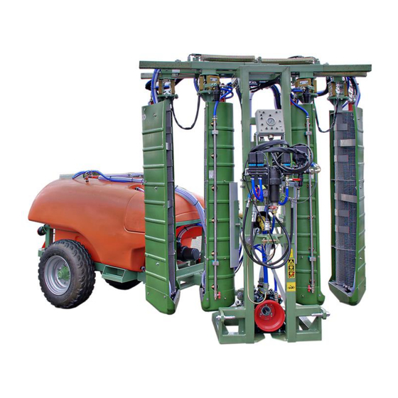
- Page 2 Operating instruction Saddle-mount fan unit with tank trailer GSG-AN-VM 2 - 72 011170-05-EN BA GSG-AN-VM / 2019-01-16...
- Page 3 Dear Customer: Thank you for choosing a LIPCO Saddle-mount fan unit with tank trailer GSG-AN-VM. We are confident that you will be satisfied with our product. In order to achieve maximum performance from your new LIPCO Saddle-mount fan unit with tank trailer GSG-AN-VM...
-
Page 4: Table Of Contents
Design details of the GSG-AN-VM - special equipment ..11 Advantages of LIPCO tunnel spray technology ...... 12 Technical data GSG-AN-VM ........... 13 Design details of the LIPCO tank trailer / standard version ..14 Technical data tank trailer ............15 Components of GSG-AN-VM ..........16 12.1. - Page 5 Trouble shooting ..............62 Storage of the machine ............64 Guarantee ................66 Functional diagram GSG-AN-VM ........... 67 Wiring diagram GSG-AN-VM (hydraulic / electrical) ....68 Notes ..................69 EC-Declaration of conformity ..........71 5 - 72 011170-05-EN BA GSG-AN-VM / 2019-01-16...
-
Page 6: Authorized Use
Operating instruction Saddle-mount fan unit with tank trailer GSG-AN-VM Authorized use LIPCO Saddle-mount fan unit with tank trailer GSG-AN-VM with recycling technology is designed for double-sided spraying of plant protection agents for vineyards, rose and berry plantations and simi- lar cultures. -
Page 7: Warnings On The Machine
Operating instruction Saddle-mount fan unit with tank trailer GSG-AN-VM Warnings on the machine Before operating the machine, always read the oper- ating manual and comply with all safety instructions! Always shut off the motor and remove the ignition key when performing maintenance or repairs! Danger of parts being catapulted while drive unit is in operation –... -
Page 8: General Safety Regulations
Operating instruction Saddle-mount fan unit with tank trailer GSG-AN-VM General safety regulations The operation of mobile plant protection units is associated with cer- tain risks. Therefore, you must comply with the following safety regu- lations: • Before operating the machine, always read the operating manual and comply with all safety instructions! •... -
Page 9: Safety Information For Handling Plant Protection Agents
Operating instruction Saddle-mount fan unit with tank trailer GSG-AN-VM Safety information for handling plant protection agents • Do not use plant protection agents that tend to gum up or con- geal – they have a negative effect on spraying. •... -
Page 10: Accident Prevention
Operating instruction Saddle-mount fan unit with tank trailer GSG-AN-VM Accident prevention Failure to comply with the simplest basic rules are causing most accidents occurring during use, maintenance or transport. Therefore, it is important that all persons involved with use of the machine are aware of and comply with the following rules: •... -
Page 11: Design Details Of The Gsg-An-Vm - Standard Equipment
Operating instruction Saddle-mount fan unit with tank trailer GSG-AN-VM Design details of the GSG-AN-VM - standard equipment • Frame with double-coat paint RAL 6011 • Hydraulic tangential fan unit width adjustment (infinitely variable / common or single action) with hydraulic cylinder. Operation via electro-hydraulic control block. -
Page 12: Advantages Of Lipco Tunnel Spray Technology
Operating instruction Saddle-mount fan unit with tank trailer GSG-AN-VM Advantages of LIPCO tunnel spray technology • The fan design causes a higher spray concentration and there- fore a more intensive deposition of spray on the plants. • Natural wind outside the fan have nearly no negative influence on spraying result. -
Page 13: Technical Data Gsg-An-Vm
Operating instruction Saddle-mount fan unit with tank trailer GSG-AN-VM Technical data GSG-AN-VM GSG-AN-VM Weight (without trailer) Required drive power AR 160 bp Pump type Fan units 1,60 Row distance - min. 1,70 – 2,40 Row width standard: 1,70 – 3,20... -
Page 14: Design Details Of The Lipco Tank Trailer / Standard Version
Operating instruction Saddle-mount fan unit with tank trailer GSG-AN-VM 10. Design details of the LIPCO tank trailer / standard version LIPCO tank trailer is available with following standard equip- ment: • frame with double-coat paint RAL 6011 • adjustable drawbar •... -
Page 15: Technical Data Tank Trailer
Operating instruction Saddle-mount fan unit with tank trailer GSG-AN-VM 11. Technical data tank trailer 1000 l Tank 1500 l Tank Weight (empty) 1,14 1,24 Tank width Fresh water container Hand washing container Standard tyres 10.0/75-15.3 tt 8 PR 11.5/80-15.3 8 PR B –... -
Page 16: Components Of Gsg-An-Vm
Operating instruction Saddle-mount fan unit with tank trailer GSG-AN-VM 12. Components of GSG-AN-VM 12.1. Filters Suction filter – 50 mesh: • Suction filter is located bet- ween spray liquid tank and pump. Suction filter • The filter insert should be checked several times daily for dirt and cleaned, if necessary. -
Page 17: Adjustment Of Fan Row Width
Operating instruction Saddle-mount fan unit with tank trailer GSG-AN-VM Pressure filter 2 – mesh width 80 mesh: • Additional pressure filters in circuit close to spray nozzles • The filter inserts must be checked several times daily and cleaned, if necessary. -
Page 18: Adjustment Of Fan Distance
Operating instruction Saddle-mount fan unit with tank trailer GSG-AN-VM 12.3. Adjustment of fan distance Hook to adjust chain length • Fan distance can be adjusted by reallocating adequate chain. Fig. 6 • Set the chain to a length, that distance between nozzles and foliage is about 16 –... -
Page 19: Tanks Of Gsg-An-Vm
Operating instruction Saddle-mount fan unit with tank trailer GSG-AN-VM 12.4. Tanks of GSG-AN-VM Spray liquid tank: Spray liquid tank Hand washing tank Fresh water tank Fig. 7 • Fill the hand-washing tank only with fresh water. The hand wash- ing tank is designed only for washing the operator’s hands after spraying process. -
Page 20: Various Valves Of Gsg-An-Vm
Operating instruction Saddle-mount fan unit with tank trailer GSG-AN-VM 12.5. Various valves of GSG-AN-VM: 2-way valve “2” 3-way valve “1” Fig. 8 Function of the 3-way valve (Fig. 8) • “Suction tank” Position: Liquid is pumped from the spray liquid tank / fresh water tank to the nozzles in the tunnel walls. - Page 21 Operating instruction Saddle-mount fan unit with tank trailer GSG-AN-VM Function of the front 2-way valve (Fig. 9) • “Machine cleaning” Position: Pump conveys fresh water from the fresh water tank through the spray nozzles to the injectors and via the recycling filter back into the spray liquid tank.
-
Page 22: Preparation
Operating instruction Saddle-mount fan unit with tank trailer GSG-AN-VM 13. Preparation In order to ensure safety and efficiency when operating the GSG-AN- the following tasks must be performed prior to starting work: • Always replace or install any damaged or missing components before operating the machine! •... -
Page 23: Attachment To Towing Vehicle
Operating instruction Saddle-mount fan unit with tank trailer GSG-AN-VM 14. Attachment to towing vehicle Prior to each operation, check the GSG-AN-VM and the towing vehi- cle for traffic and operational safety! • Secure the vehicle against rolling by means of the parking brake... - Page 24 12-V plug-in Fig. 12 • Figure 12 shows a fully electric control box in non-operational status, attached to the front of the GSG-AN-VM; the mount-ing bracket for the control box is suspended in two hooks on the GSG-AN-VM frame. For standard version without built-in hydraulic: •...
-
Page 25: Information For Hydraulic Connection
Operating instruction Saddle-mount fan unit with tank trailer GSG-AN-VM 14.1. Information for hydraulic connection • Note: Maximum allowable hydraulic pressure from tractor side is 120 bar – at operating temperature. Higher pressure can damage the cross flow fan hydraulic motor. - Page 26 Operating instruction Saddle-mount fan unit with tank trailer GSG-AN-VM • Note: Any dirt within the hydraulic circuit will damage the sealing of hy- draulic valves and hydraulic motor of the fan. The hydraulic motors of the fans are excluded from warranty be- cause considered as wearing parts.
-
Page 27: Attachment Of The Universal Joint Shaft
Operating instruction Saddle-mount fan unit with tank trailer GSG-AN-VM 15. Attachment of the universal joint shaft • Prior to connecting or detaching the universal joint shaft, always make sure to switch off the power take-off shaft and motor and to remove the ignition key! •... - Page 28 Operating instruction Saddle-mount fan unit with tank trailer GSG-AN-VM Universal joint shaft guard: • Connected safety chains pre- vent the two-sided universal joint shaft guard from turning during operation. Universal joint shaft guard Fig. 17 • Picture shows universal joint shaft on lateral support (e.g. during storage in wintertime) •...
-
Page 29: Attaching The Lipco Tank Trailer
Operating instruction Saddle-mount fan unit with tank trailer GSG-AN-VM 16. Attaching the LIPCO tank trailer Trailer coupling Coupling claw of the GSG-AN- Hexagon bolt Coupling head of tank trailer. Crown nut / Washer / Split pin Fig. 18 • Insert and secure the coupling head of the tank trailer in the cou-... -
Page 30: Driving On Roads With The Gsg-An-Vm
Operating instruction Saddle-mount fan unit with tank trailer GSG-AN-VM 17. Driving on roads with the GSG-AN-VM • Special points to be observed when driving on roads! Lights: • The lights of the tank trailer must be properly connected to the towing vehicle to ensure safe operation in traffic. -
Page 31: Operating The Lipco Gsg-An-Vm
Operating instruction Saddle-mount fan unit with tank trailer GSG-AN-VM 18. Operating the LIPCO GSG-AN-VM • Caution: Do not use plant protection agents that tend to gum up or con- geal – they have a negative effect on spraying. 18.1. Determining the amount of spray liquid needed... -
Page 32: Calculation Of The Driving Speed
Operating instruction Saddle-mount fan unit with tank trailer GSG-AN-VM 18.3. Calculation of the driving speed The driving speed is calculated based on the following formula: Measured path (m) x 3.6 Driving speed (km/) Time (sec.) Sample calculation based on the following data:... -
Page 33: Nozzle Selection And Output Volume
Operating instruction Saddle-mount fan unit with tank trailer GSG-AN-VM 18.4. Nozzle selection and output volume In standard version, GSG-AN-VM will be shipped with flat fan venturi nozzles ALBUZ® CVI 80 - green. (Other nozzles upon request) • During assembly, make sure that the seal is properly locat- ed in the fan nozzle. -
Page 34: Nozzle Chart
Operating instruction Saddle-mount fan unit with tank trailer GSG-AN-VM 18.5. Nozzle chart 34 - 72 011170-05-EN BA GSG-AN-VM / 2019-01-16... -
Page 35: Checking Liquid Output At The Gsg-An-Vm
Operating instruction Saddle-mount fan unit with tank trailer GSG-AN-VM 18.6. Checking liquid output at the GSG-AN-VM General: Check the liquid output once each year at the beginning of the season, in the case of changes in the liquid circulation or after replacing nozzles. - Page 36 Operating instruction Saddle-mount fan unit with tank trailer GSG-AN-VM • Switch off the GSG-AN-VM and fill the tank again up to the se- lected marking on the filling mandrel. • Make a spray test for at least 2 min. •...
-
Page 37: Nozzle Adjustment During Operation
Operating instruction Saddle-mount fan unit with tank trailer GSG-AN-VM 18.7. Nozzle adjustment during operation Before blossoming: During / after blossoming / with full foliage: nozzle 6 closed nozzle swiveled 20° nozzle 5 downwards closed nozzle 4 closed nozzle 3 closed... -
Page 38: Spray Nozzle Adjustment
Operating instruction Saddle-mount fan unit with tank trailer GSG-AN-VM 18.8. Spray nozzle adjustment • To switch off a nozzle, turn it either 90° downward or 90° upward. (Fig. 21) Fig. 21 The nozzles used have the following positions: - 90 degrees / straight down stop... -
Page 39: Worth Knowing About Proper Nozzle Adjustment
Operating instruction Saddle-mount fan unit with tank trailer GSG-AN-VM 18.9. Worth knowing about proper nozzle adjustment The nozzle distance is about 270 mm. To get an equal spaying pattern without any streaking use a dis- tance 160 – 260 mm between nozzles and foliage. -
Page 40: Adjustment Of Outer Fan
Operating instruction Saddle-mount fan unit with tank trailer GSG-AN-VM Schematic top view: 18.10. Adjustment of outer fan Because of fluidic reasons, each outer fan must be swiveled about 3° against driving direction. The angle can be adjusted via the clamping connection in the head area. -
Page 41: Rpm Fan Setting
Operating instruction Saddle-mount fan unit with tank trailer GSG-AN-VM 18.11. RPM fan setting Two parameters determine the speed of the cross-flow fan as well as the volume of produced air. These are: Oil volume coming from tractor side (l/min) as well as oil pres- sure. -
Page 42: Recycling Unit
Operating instruction Saddle-mount fan unit with tank trailer GSG-AN-VM 18.12. Recycling unit • The recycling unit enables recovering of unused spray liquid. • To recover unused spray liquid, the cross-flow fan units are de- signed with a collector at the bottom, including a built-in injector. - Page 43 Operating instruction Saddle-mount fan unit with tank trailer GSG-AN-VM For spraying agents that tend to foam, it may be necessary to close the valve far enough to allow suction without the inclusion of excess air. In the event of excessive foaming, we recommend the use of an anti-foaming agent in the spray liquid.
- Page 44 Operating instruction Saddle-mount fan unit with tank trailer GSG-AN-VM Control box: • The picture shows a control box sample. The no. of switch- es may differ depending on or- dered functions. (Fig. 26) Fig. 26 The return line leads from the injector through the recycling filter to the spray tank.
-
Page 45: Setting The Gsg-An-Vm
600 x 6 x 2 x 2 Calculation: 24 l/min The calculated liquid discharge for the complete GSG-AN-VM is in this case 24 l/min. For the required quantity of plant protection agent for the intend- ed purpose, please follow the instructions for the plant protection agent. -
Page 46: Calculation Of The Required Plant Protection Agent/Spray
Operating instruction Saddle-mount fan unit with tank trailer GSG-AN-VM 19.2. Calculation of the required plant protection agent/spray For the required quantity of plant protection agent for the in- tended purpose, please follow the instructions for the plant pro- tection agent. -
Page 47: Sequence For Checking The Dosing And Distribution Accuracy Of The Gsg-An-Vm
Operating instruction Saddle-mount fan unit with tank trailer GSG-AN-VM • Note: Never prepare more spray liquid than necessary. For the GSG- AN-VM the recycling rate should be included in the calculation. This is especially important for the final spraying. 19.3. Sequence for checking the dosing and distribution accura-... -
Page 48: Procedure Of Spray Test
Operating instruction Saddle-mount fan unit with tank trailer GSG-AN-VM 20. Procedure of spray test • Fill GSG-AN-VM spray liquid tank partially with non-pressurized water. Put 3-way valve (Fig. 27) in position „Suction Tank Fig. 27 • Position: “Suction tank” Liquid is pumped from the spray liquid tank / fresh water tank to the nozzles in the cross-flow fan units. -
Page 49: Preparation Of Spraying Liquid
Operating instruction Saddle-mount fan unit with tank trailer GSG-AN-VM 21. Preparation of spraying liquid • Prepare only the quantity of plant protection agent as required. • Fill approximately 75% of the calculated water quantity in the spray liquid tank. When filling with water from the drinking water supply, do not immerse water hose in the spray liquid. - Page 50 Operating instruction Saddle-mount fan unit with tank trailer GSG-AN-VM Note: • This ball valve is also used for quick cleaning of pressure filter 1. Closing this ball valve too much will have a negative influence on quick cleaning process for pressure filter 1.
- Page 51 Operating instruction Saddle-mount fan unit with tank trailer GSG-AN-VM Filling level indicator: • Note the max. filling level of the spray liquid tank on the filling level indicator. Level indicator (hose) Do not fill in more than maxi- mum tank capacity.
-
Page 52: Emptying The Gsg-An-Vm After Use
Operating instruction Saddle-mount fan unit with tank trailer GSG-AN-VM 22. Emptying the GSG-AN-VM after use Use plant protection agents only on agricultural / forested / horticultural surfaces. This applies also to the remaining agent, which remains in the tank be- cause of technical reasons in the tank. -
Page 53: Residual Volume
Operating instruction Saddle-mount fan unit with tank trailer GSG-AN-VM 23. Residual volume For technical reasons, a certain volume of liquid will always stay in the tank. Note: For working on slope, the maximum slope inclination is 5°. The below indicated remaining volume applies up to an inclination of 5°, higher inclination up to maximum allowed 10°... - Page 54 Operating instruction Saddle-mount fan unit with tank trailer GSG-AN-VM • Set the 3-way (“1”) valve to the middle position “Clean suction filter” (Fig. 32). This will shut-off the agent spraying circuit. 2-way valve “2” 3-way valve “1” Fig. 32 •...
-
Page 55: Cleaning Of Gsg-An-Vm After Use
Operating instruction Saddle-mount fan unit with tank trailer GSG-AN-VM 25. Cleaning of GSG-AN-VM after use Clean the machine on an untreated surface on the field. Clean the machine with a spraying gun, which is supplied by water out of the fresh water tank. - Page 56 Operating instruction Saddle-mount fan unit with tank trailer GSG-AN-VM Cleaning spray liquid tank inside: • Inside the spray liquid tank a rotating nozzle is located for inside cleaning.(Fig. 36) Fresh water from the fresh wa- ter tank is feeding the rotating nozzle.
-
Page 57: Maintenance
Operating instruction Saddle-mount fan unit with tank trailer GSG-AN-VM 26. Maintenance • Caution: Always secure the spray unit from rolling or tilting during mainte- nance and repair work. Actions for keeping the machine in optimum operating condition: Collector cross-flow fan: •... - Page 58 Operating instruction Saddle-mount fan unit with tank trailer GSG-AN-VM Draw bar tank trailer: • Lubricate nipples of draw bar every 6 months Lubrication nipple (2x) Fig. 40 Pump: Pump oil tank • Check pump oil level Check oil in inspection glass on a regular base;...
- Page 59 Operating instruction Saddle-mount fan unit with tank trailer GSG-AN-VM Air receiver: Valve for pressure check of air receiver. • Set the pressure of the air re- ceiver to approx. 20% of the spraying pressure and check from time to time.
- Page 60 Operating instruction Saddle-mount fan unit with tank trailer GSG-AN-VM Recycling injector: • After repair or cleaning, make sure that the injector is re- assembled correctly. (Fig. 44) Pay attention to the diameter “d”, as there are different ver- sions – see also spare parts list.
-
Page 61: Machine Inspection
Operating instruction Saddle-mount fan unit with tank trailer GSG-AN-VM 27. Machine inspection 27.1. Pressure check A pressure check may become necessary during a machine in- spection. Please pay attention to the following: Interface for pressure check: • To check the system pressure (e.g. -
Page 62: Trouble Shooting
Operating instruction Saddle-mount fan unit with tank trailer GSG-AN-VM 28. Trouble shooting The following table will help you to quickly locate and eliminate any malfunctions. Location of fault Possible cause Solution Incorrect suction of Recycling filter blocked Clean recycling filter... - Page 63 Operating instruction Saddle-mount fan unit with tank trailer GSG-AN-VM Location of fault Possible cause Solution Insufficient pump capacity Pressure filter blocked Clean pressure filter Shut-off valve for tank Both valves must be cleaning and/or valve for closed flushing device still open...
-
Page 64: Storage Of The Machine
Operating instruction Saddle-mount fan unit with tank trailer GSG-AN-VM 29. Storage of the machine If the GSG-AN-VM will be no more used for a longer period, you should perform the following steps: • Check the function of all moving parts and replace worn or dam- aged parts. - Page 65 Operating instruction Saddle-mount fan unit with tank trailer GSG-AN-VM • Remove nozzles, clean (e.g. with a soft brush – do not use hard objects!) and store in a protected place. • Remove filters, clean and check for damage. • Check oil level of pump, check membranes and valves for dam- age.
-
Page 66: Guarantee
Operating instruction Saddle-mount fan unit with tank trailer GSG-AN-VM 30. Guarantee For more details please refer to: https://www.lipco.com/en/downloads/ 66 - 72 011170-05-EN BA GSG-AN-VM / 2019-01-16... -
Page 67: Functional Diagram Gsg-An-Vm
Operating instruction Saddle-mount fan unit with tank trailer GSG-AN-VM 31. Functional diagram GSG-AN-VM Pressure filter 14. 2-way valve Electric valves (spray liquid/fresh water) Pressure control valve 15. Suction filter 3-way valve Electric control box (drain valve/suction filter) Safety pressure control valve 17. -
Page 68: Wiring Diagram Gsg-An-Vm (Hydraulic / Electrical)
Operating instruction Saddle-mount fan unit with tank trailer GSG-AN-VM 32. Wiring diagram GSG-AN-VM (hydraulic / electrical) For more details please refer to: https://www.lipco.com/en/downloads/ 68 - 72 011170-05-EN BA GSG-AN-VM / 2019-01-16... -
Page 69: Notes
Operating instruction Saddle-mount fan unit with tank trailer GSG-AN-VM 33. Notes 69 - 72 011170-05-EN BA GSG-AN-VM / 2019-01-16... - Page 70 Operating instruction Saddle-mount fan unit with tank trailer GSG-AN-VM 70 - 72 011170-05-EN BA GSG-AN-VM / 2019-01-16...
-
Page 71: Ec-Declaration Of Conformity
Operating instruction Operating instruction Saddle-mount fan unit with tank trailer GSG-AN-VM Saddle-mount fan unit with tank trailer GSG-AN-VM 34. EC-Declaration of conformity Manufacturer: person authorized to compile the technical files: LIPCO GmbH Guenther Bauer Am Fuchsgraben 5b Ingenieurbuero Bauer D-77880 Sasbach Scherzinger Weg 46 Tel. - Page 72 Design: mail@bauer-ib.com...
Need help?
Do you have a question about the GSG-AN-VM and is the answer not in the manual?
Questions and answers