Table of Contents
Advertisement
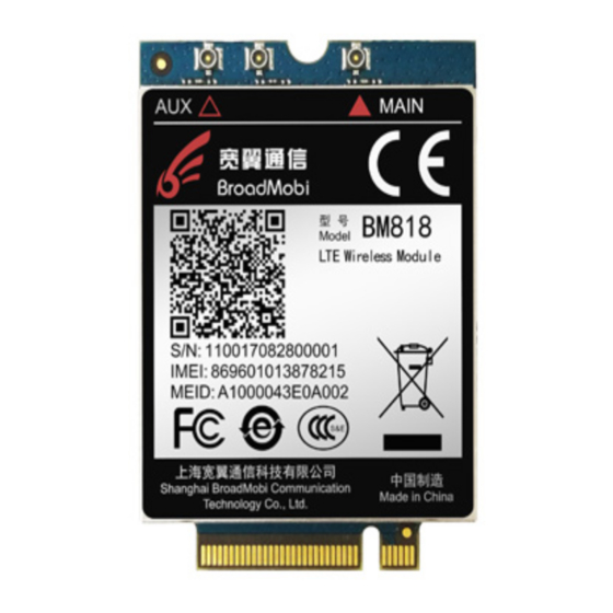
BM818
Operation manual_V1.4
Important Statements
Copyright Notice
All right reserved: ShangHai broad mobi Communication
Technology Co LTD
This material and contains all of the content belong to
ShangHai broad mobi Communication Technology Co
LTD, and it is protected by Chinese law and any relevant
copyright from international convention. anyone who
donothave the authorization in written form by
ShangHai broad mobi Communication Technology Co
LTD cannot copy, spread, modify or other methods to
use part or all of content, the offender will be
investigated and affixed legal liability
。
BM818Operation Manual
1/34
Advertisement
Table of Contents

Summary of Contents for BroadMobi BM818
- Page 1 BM818 Operation manual_V1.4 Important Statements Copyright Notice All right reserved: ShangHai broad mobi Communication Technology Co LTD This material and contains all of the content belong to ShangHai broad mobi Communication Technology Co LTD, and it is protected by Chinese law and any relevant copyright from international convention.
- Page 2 Unguaranteed Statements Shanghai broad mobi Communication Technology Co LTD does not make express or implied statement or guarantee for any details from this document, and also not be responsible for Specific purpose of marketability and applicability or any indirect, special, or jointly any loss .
-
Page 3: Table Of Contents
development of technological, and version change without prior notice. Contents Introduction ………………………………………………………………….……………..6 1.1. Purpose .…………………………………………………………......6 1.2. General view ..……………………………..…………….…………………………..6 Brief introduction …..…………………………………………….……………………..6 2.1. Necessaryequipment .…………………………………….…....7 Set up and Install ...………………………………………………………..…….……...8 3.1. The Construct of Hardware Environment ………………………..……..8 3.1.1. How put in or out SIM/USIM card ..………………………………8 3.1.2. - Page 4 4.1. How to use USB cable to communicate ………………………………..24 4.2. How to make data connection …………………………………………..…25 4.3. How to make voice call out ………………………………..…………………30 4.4. How to check module information and SIM card status ……….31 4.5. How to set airplane mode …………………………….……………………..32 CAUTION..………………………………………………………………………………….33 BM818Operation Manual 4/34...
-
Page 5: Introduction
1. Introduction BM818 EVB use for testing the function and performance of BM818module , and provide relevant assessment to help customer develop application. Purpose This document detailed describes the basic function of BM818 and point out the main feature is data transmission. -
Page 6: Necessaryequipment
USB interface, SIM card interface, MINI PCI-E port 3 ports. 2.1 Necessary equipment The chart 1 detailed describe the necessary equipment for testing environment BM818. Chart 1:EVB Kit List Equipment EVB kit whether or Description not Include Use for BM818test... -
Page 7: Set Up And Install
USB Cable Standard USB Antenna Antenna has two parts: 1 ) diversity antenna and main antenna 2)antenna patch cord BM818 Board SIM/USIM Need a SIM/USIM Card have balance Chart 2 Antenna Gain Gain (dBi) Frequency (MHz) 3.08 2.24 1.44 1.14 2.80... -
Page 8: The Construct Of Hardware Environment
The Construct of Hardware Environment How put in or out SIM/USIM card How to link module How to link main antenna How to link diversity antenna How to link USB cable How to power on ... - Page 9 (Picture 1) (Picture 2) 2) Put SIM Card into the slot, make sure SIM chip upwards, put into the SIM slot on EVB Boar. See Picture 3 and 4. BM818Operation Manual 9/34...
-
Page 10: How To Link Module
(Picture 3) (Picture 4) 3.1.2. How to link module Put module into development board after finish install SIM BM818Operation Manual 10/34... - Page 11 card: 1) Put EVB Board right side up, and put module into Mini PCI-E connector. See Picture 5 and 6. BM818Operation Manual 11/34...
- Page 12 BM818Operation Manual 12/34...
- Page 13 (Picture 5) (picture 6) 2) Put module into Mini PCI-E with screw fixation. See Picture 7。 BM818Operation Manual 13/34...
-
Page 14: How To Link Main Antenna
(Picture 7) 3.1.3. How to link main antenna Before the link antenna, need finish put in SIM card and Module. 1) Antenna interface located on top right of module with sign “M”. See Picture 8. (Picture 8) BM818Operation Manual 14/34... - Page 15 2) Spike RF Patch cord into module connector smoothly. See Picture 9。 (Picture 9) 3) Tightening antenna SMA contact and RF patch cord SMA contact. See Picture 10。 (Picture 10) BM818Operation Manual 15/34...
-
Page 16: How To Link Diversity Antenna
3.1.4. How to link diversity antenna Before link diversity antenna, need finish put SIM Card and module in, and link the main antenna 1) The antenna interface is located on the top left of module with sign “D”. See Picture 11. (Picture 11) 2) Spike RF Patch cord into module connector smoothly. -
Page 17: How To Link Usb Cable
(Picture 12) 3) Tightening antenna SMA contact and RF patch cord SMA contact. See Picture 13 (Picture 13) 3.1.5.H ow to link USB cable Follow the step to link USB cable: BM818Operation Manual 17/34... -
Page 18: How To Power On
PC.See Picture14. (Picture 14) 3.1.6. How to power on BM818 only support electrify power on, all need just put the port A of USB cable into PC, and module will auto power 3.1.7. How to power off BM818 support outage shutdown, module will shut down when VBAT blackout. -
Page 19: The Construct Of Software Environment
3.2 The Construct of Software Environment 3.2.1. How to install driver 1) First use USB cable to connect PC and module, power module on, Windows will popup new equipment window, choose“No, not this time”, then click”Next” Picture 15: find new hardware 2)... - Page 20 Picture 16: choose the method for install driver BM818 choose the path that driver file is located, and click “Yes”; 3) Click“Next” Picture 18: Choose driver file path 2 in XP BM818Operation Manual 20/34...
- Page 21 4) The driver is installing Picture 19: driver install 5) Wait for notes “Completing hardware Upgrade wizard” ,click ” Finish ” finish the install. Picture 20: Finish the driver install BM818Operation Manual 21/34...
-
Page 22: How To Upgrade Firmware
Picture 21: module appear in device manager 3.2.2. How to upgrade firmware BM818 provide 1key upgrade tool for Windows, step of upgrade firmware: 1) Use USB cable to connect PC and BM818, double-click “GUI_dl”when the device manager recognize com port. See Picture 22: BM818Operation Manual 22/34... - Page 23 Picture 22: the window of firmware upgrades 1 2) Follow the note to press “Download”, start to upgrade. See Picture 23 Picture 23: Firmware is upgrading There is note “Success to upgrade” when it all finished. 3) BM818Operation Manual 23/34...
-
Page 24: Debugging And Testing
The EVB through USB to communicate,can use for phone call, connect internet, this chapter will discuss in detail. How to use USB cable to communicate 1) The communication methods for PC and BM818 is AT command,to test whether PC successfully communicate BM818 by sending AT command. - Page 25 Open HyperTerminal, choose AT port. 2) Picture 25: Choose the port for HyperTerminal 3) Choose baud rate 9600, choose none for flow control, other setting default. See Picture 26 Picture 26: ConfigurationHyperTerminal 4) Sending AT,check it is or isn’tcommunicated. See Picture 27 BM818Operation Manual 25/34...
-
Page 26: How To Make Data Connection
Picture 27: UsingHyperTerminal sending at How to make data connection Put SIM/USIM card that support data traffic into EVB board, connect antenna right, though USB cable to connect PC and power on module. 1) through NDIS to dial a) type “at$qcrmcall=1,1”, create network connection. Picture 28: using HyperTerminal to send AT command to NDIS dial BM818Operation Manual 26/34... - Page 27 b) Type“at$qcrmcall=0,1” , to disconnect Network connection. 2)through MODEM to dial A)open Network Connections to choose to connect Internet and click “下一步 Next” Picture 29: Choose Network Connection B) Choose ”Set up my Connection manually”, click “Next” BM818Operation Manual 27/34...
- Page 28 Picture 30: Create new Network connection C) Choose “Connect using a dial-up modem” Picture 31:Choose Modem to Dial D)type the number u want to dial, the user and password need according different carriers. For example, the user and password for BM818Operation Manual 28/34...
-
Page 29: How To Make Voice Call Out
China Union 3G and 4G is empty (not type any character ) the number is *99#, then choose “Connect” Picture 32:Configuration Network Connection E)there is a note after Network Connection is successful. Picture 33:Dial success 4.3. How to make voice call out BM818Operation Manual 29/34... - Page 30 A. Put SIM/USIM card which support voice service into EVB board. B. Open the HyperTerminal, configuration same as Picture 22 and 23. C. The AT command for dial phone call is “ATDXXX;”. For example, we make a call to 10010, type “ATD10010;” Picture 34:Using HyperTerminal dial number D.
-
Page 31: How To Check Module Information And Sim Card Status
Picture 35:Hand up phone call 4.4. How to check module information and SIM card status A. Put SIM/USIM Card which supports voice service into EVB board. a) Open the HyperTerminal, configuration same as Picture 22 and 23. Type “ATI”, shows module information; type “AT+CPIN?” shows SIM Card Status. -
Page 32: How To Set Airplane Mode
Picture 36:Show module information and SIM Status Warning:SIM Card shows “Ready” indicate SIM status is normal, if it shows other, it means unmoral, please make sure your SIM is whether or not valid, or has pin. 4.5. How to set airplane mode Type ATCommad“AT+CFUN=4”, enter intoairpalne mode. - Page 33 This equipment should be installed and operated with minimum distance 20cm between the radiator & your body. when the module is installed inside another device, This exterior label should use wording such as the following: “Contains Transmitter Module FCC ID:2AON8-BM818 “ BM818Operation Manual 33/34...
-
Page 34: Caution
CAUTION: 1.Labelling requirements. This device complies with Part 15 of the FCC Rules. Operation is subject to the condition that this device does not cause harmful interference. 2. Information to user. Any Changes or modifications not expressly approved by the party responsible for compliance could void the user's authority to operate the equipment. - Page 35 to radio or television reception, which can be determined by turning the equipment off and on, the user is encouraged to try to correct the interference by one or more of the following measures: -Reorient or relocate the receiving antenna. -Increase the separation between the equipment and receiver.
Need help?
Do you have a question about the BM818 and is the answer not in the manual?
Questions and answers