Table of Contents
Advertisement
Advertisement
Table of Contents

Summary of Contents for LifeGuard Lift LifeGuard Power Lift Series
- Page 1 LifeGuardLift OWNERS MANUAL LifeGuard Power Lift™ Model #100287A Rev: 2/14/11...
-
Page 2: Table Of Contents
C. Battery Storage 3. REMOTE CONTROLS 4. OPERATING INSTRUCTIONS A. Raising and Lowering Seat B. Rotation C. Pool Entry D. Pool Exit 5. SAFETY AND CARE 6. TROUBLESHOOTING 7. SPECIFICATIONS 8. PARTS LIST 9. WARRANTY ©2011 LifeGuard Lift, Inc. All rights reserved... -
Page 3: Assembly Instructions
1. ASSEMBLY INSTRUCTIONS Tools: 2 - 9/16 open end wrenches/sockets 1 - Flat head screw driver 1 – Phillips head screw driver 1 - 1/4” Allen wrench A. Lift Assembly (Note: See Drawings on Pages 6 & 7) Attach the anchor adapter to the anchor. Insert the mast assembly into the anchor adapter. -
Page 4: Setup
Bolt the foot rest to the flange under the seat with two (2) 3/8” bolts with a washer on each side. Tighten the bolts to 15-ft lbs. Make sure that the foot rest is inside the flange. Install a fully charged battery and make two (2) electrical connections. - Page 6 DOWN TUBE AND SEAT ASSEMBLY...
-
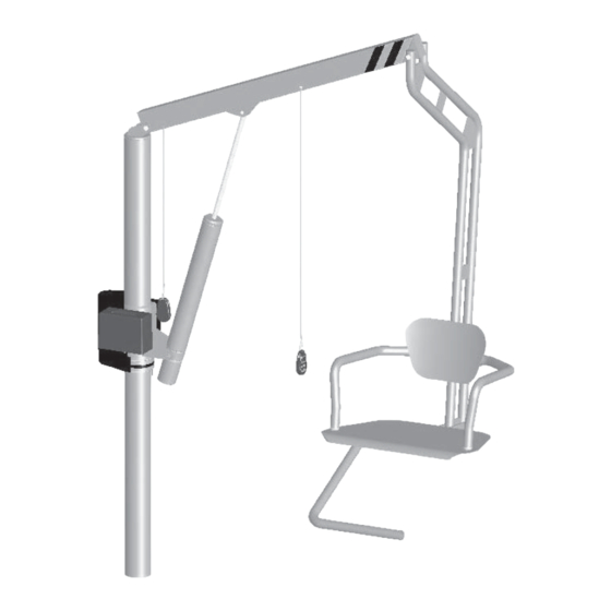
Page 7: Control System
2. CONTROL SYSTEM The LifeGuard Power Lift battery operating system includes a TechTronic 12V wireless waterproof locking control box with two (2) convenient wireless waterproof remote controls. (2) 12V wheelchair grade batteries are included, one for operation, and the other as a backup. A battery charger equipped with an automatic shut off control is included. -
Page 8: Remote Controls
3. REMOTE CONTROLS The lift is equipped with two (2) conveniently located wireless waterproof remote controls. One remote control is for the operator and the other is for an assistive operator. The controls are brightly marked for ease of operation. The remote controls programmed to perform four (4) functions as shown in drawing. - Page 9 Counterclockwise Rotation: Pressing the counterclockwise button rotates the lift in a counterclockwise direction. The lift will continue to rotate in this direction until the button is released. WARNING: Failure to observe the following warnings can result in severe injury or death. WARNING: Operator of the lift must read and understand the operating instructions.
-
Page 10: Pool Entry
C. Pool Entry When the lift is in place, make a visual inspection, unlock the control box, and make a short test run. Using the wireless hand controller, rotate the seat in the counterclockwise direction until it reaches a safe and comfortable position for transfer. -
Page 11: Pool Exit
D. Pool Exit When water activity is finished, the occupant returns to the seat, using the permanent seat arm and pool edge to center the occupant’s weight on the seat. Return the left arm rest to its down position and fasten the safety belt. -
Page 13: Safety And Care
• If any WARNING or USE labels faded or become illegible, • call LifeGuard Lift Inc. at 1-800-688-3958 and we will mail you replacements at no charge. WARNING! Storing the lift in a pump or storage room, where pool or other corrosive chemicals or materials are stored may damage the lift and will void the Warranty. -
Page 14: Specifications
7. SPECIFICATIONS Dimensions/Capacity: Maximum Lifting Capacity 350 lbs. Range of Motion: Rotation 360 degrees 18.2” height Lifting Range 26.6” depth below deck (dimensions for seat face height) Overall Height 72.4” boom up, 56.3” boom down Overall Swept Radii 56” Power 12V D.C. -
Page 15: Parts List
8. Parts List DRAWING # QUANTITY PART NUMBER DESCRIPTION 500269A Linear Actuator - stroke 15” 410266A 1/4” - 20 x 5/8” flat washer screw 510255A Receiver, TouchTronics™ 410156A Truss Head #8-32 x .25 SS 300257A Mounting plate for controller Belt Idler, Complete NCL 200116A Fasteners 400115A... -
Page 17: Warranty
Any alteration or repair or without the prior written approval by LifeGuard Lift, Inc. To initiate a warranty claim, the owner of an LifeGuard Lift, Inc. product must submit to LifeGuard Lift, Inc. a Return Merchandise Authorization form stating the date and place of purchase, a full...
Need help?
Do you have a question about the LifeGuard Power Lift Series and is the answer not in the manual?
Questions and answers
How do you keep the chair from moving
To prevent the LifeGuard Power Lift Series chair from moving, remove and store the lift when it is not in use. Additionally, do not move the lift with the battery and battery cover in place.
This answer is automatically generated