
Related Manuals for DewertOkin System DD11

Summary of Contents for DewertOkin System DD11
- Page 1 Installation Instructions (Translation of the original installation instructions) DD11 System DD21 System...
-
Page 3: Document Revision History
• changes made to this product which have not been approved by DewertOkin, or • the use of replacement parts which have not been approved or manufactured by DewertOkin. We reserve the right to make unannounced technical changes in the course of our continual... -
Page 4: Table Of Contents
System DD11 / System DD21 Document revision history ..........................3 Disclaimer and exclusion of liability ....................... 3 Creation of a complete operating instruction manual for the entire end product ........3 General Information ....................6 About these installation instructions ....................6 Safety notices within the installation instruction and the operating instructions for the entire machine .............................. - Page 5 System DD11 / System DD21 Functions of the HSCO control keypad ................... 53 Functions of the HSU Varioline control keypad ................54 Functions of the HSU control keypad ....................55 Functions of the HSF control keypad ....................57 Functions of the TOUCHbasic-inlay control keypad ..............60 Functions of the TOUCHbasic-down control keypad ..............
-
Page 6: General Information
General Information System DD11 / System DD21 General Information About these installation instructions These installation instructions are not specific operating instructions for the end product. Rather, they describe the functions of the control keypads and the installation of the DD11/DD21 system compo- nents: •... -
Page 7: Safety Notices Within The Installation Instruction And The Operating Instructions For The Entire Machine
System DD11 / System DD21 General Information Safety notices within the installation instruction and the operating instruc- tions for the entire machine The manufacturer of the complete machine (the end product) is only permitted to operate the DD11/DD21 lifting columns (by itself an incomplete machine) •... -
Page 8: Safety Notices
Safety notices System DD11 / System DD21 Safety notices Proper and intended usage The DD11/DD21 system is intended: • for adjusting the height of tables in conjunction with the SMART/COMPACT control units and the DD11/DD21 lifting columns from DewertOkin. It may only be used for applications where unintended motion cannot lead to damage. -
Page 9: Selection And Qualification Of Personnel
Do not allow children to play with this device. The cleaning and user maintenance must not be carried out by children without supervision. You should only use spare parts which have been manufactured or approved by DewertOkin. Only these parts will guarantee a sufficient level of safety. -
Page 10: System Component Description
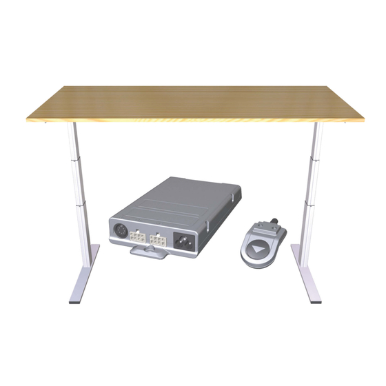
System component description System DD11 / System DD21 System component description The DD11/DD21 system uses lifting columns to adjust the height of tables. A table-mounted control keypad and the SMART/COMPACT control units can be used for the adjustments. The DD11/DD21 system variants differ by: •... - Page 11 System DD11 / System DD21 System component description Max. 2000 800 - 1000 Figure 2 Example: DD21 system with two DD21 lifting columns A Control keypad B Tabletop C SMART or COMPACT control units D DD21 lifting column (double telescopic)
-
Page 12: Mounted Complete System Deskframe C Dd-B 1Xcb
System component description System DD11 / System DD21 Mounted complete system DESKFRAME C DD-B 1xCB Max. 2000 Max. 2000 800 - 1000 Max. 1000 Max. 1000 Figure 3 Example: DD11 system with three DD11 lifting columns A Control keypad B Tabletop... - Page 13 System DD11 / System DD21 System component description Max. 2000 Max. 2000 800 - 1000 Max. 1000 Max. 1000 Figure 4 Example: DD21 system with three DD21 lifting columns A Control keypad B Tabletop C COMPACT control unit D DD21 lifting column (double telescopic)
-
Page 14: Smart And Compact Control Units
System component description System DD11 / System DD21 SMART and COMPACT control units The SMART and COMPACT control units have an enclosure with connections for the power supply, lifting columns, and for the control keypad. 3.3.1 SMART control unit The SMART control unit is used for adjusting one or two lifting columns. -
Page 15: Control Keypads
System DD11 / System DD21 System component description 3.4 Control keypads The control keypads are used to adjust the table height, to save positions (optional), and to adjust motor group 2. The table positions and optional saved (programmed) positions can be moved to di- rectly. - Page 16 System component description System DD11 / System DD21 3.4.3 HSU Varioline control keypad The HSU Varioline control keypad has two keys for the up and down adjustments. Figure 9 HSU Varioline control keypad key (adjusting down) B Mounting surface C Connection cable key (adjusting up) 82774 2.0...
- Page 17 System DD11 / System DD21 System component description 3.4.4 HSU control keypad The HSU control keypad has two keys for the up/down adjustment movements, four memory keys, a save key and a display. Figure 10 HSU control keypad B Mounting surface...
- Page 18 System component description System DD11 / System DD21 3.4.5 HSF control keypad The HSF control keypad has two keys for the up/down adjustment movements, four memory keys, two keys for motor group 2, a save key and a display. Figure 11...
- Page 19 System DD11 / System DD21 System component description 3.4.6 TOUCHbasic-inlay control keypad The TOUCHbasic-inlay control keypad has two keys for the up and down adjustments. Figure 12 TOUCHbasic-inlay control keypad key (adjusting down) key (adjusting up) 3.4.7 TOUCHbasic-down control keypad The TOUCHbasic-down control keypad has two keys for the up and down adjustments.
- Page 20 System component description System DD11 / System DD21 3.4.8 TOUCHfx control keypad The TOUCHfx control keypad has two keys for the up/down adjustment movements, four memory keys, a save key and a display. Figure 14 TOUCHfx control keypad B Mounting surface...
- Page 21 System DD11 / System DD21 System component description 3.4.9 TOUCHdown control keypad The TOUCHdown control keypad has two keys for the up/down adjustment movements, four mem- ory keys, a save key and a display. Figure 15 TOUCHdown control keypad B Mounting surface...
- Page 22 System component description System DD11 / System DD21 3.4.10 TOUCHinlay control keypad The TOUCHinlay control keypad has two keys for the up/down adjustment movements, two memory keys, a save key and a display. Figure 16 TOUCHinlay control keypad -key (adjusting down)
-
Page 23: Lifting Columns
System DD11 / System DD21 System component description Lifting columns The main components of the DD11/DD21 lifting columns are the electric motor, the telescopic col- umns for adjustments, the outer support column, and the connecting cable. The end product will be attached to the motor housing of the lifting column. - Page 24 System component description System DD11 / System DD21 3.5.2 DD21 lifting column (double telescopic) Figure 18 Major components of the DD21 lifting column A Connection cable B Head of the lifting column C Outer column with two internal telescopic D Foot of the lifting column columns 82774 2.0...
-
Page 25: System Configurations
System DD11 / System DD21 System configurations System configurations Depending on the particular configuration, the DD11/DD21 system can be combined with up to three lifting columns. The configurations with two and three lifting columns are described below: Configuration 1: SMART control unit with one or two DD11/DD21 lifting columns and a control keypad Installation steps: •... - Page 26 System configurations System DD11 / System DD21 Configuration 2: SMART control unit with one, two or three DD11/DD21 lifting columns and a control keypad Installation steps: • Install the lifting columns (see section 5.2, page 29) • Install the control keypads (see section 5.3, page 33) •...
-
Page 27: Installation
Fasten all cables using sufficient strain relief and kink prevention methods. 5.1.1 Reliability The safety and reliability of the end product containing DewertOkin components can be ensured by using the proper construction methods as described below. Overheating A thermal monitor switches the SMART/COMPACT control unit off if it overheats. - Page 28 (e.g. crushing injuries). Structural modifications may only be made after consulting with DewertO- kin and receiving our consent. Follow all instructions from DewertOkin, especially those found in these installation instructions.
-
Page 29: Installing The Dd11 And Dd21 Lifting Columns
System DD11 / System DD21 Installation Installing the DD11 and DD21 lifting columns Before installing and connecting the DD11/DD21 lifting columns, make sure that you are observing all of the safety notices found in the "Safety notices to observe during installation" section. - Page 30 Installation System DD11 / System DD21 Figure 20 Mounting the table base: A Base plate B M6 bolts (8.8) C Foot of the lifting column 1 Use four screws to attach the table base to the foot end of the DD11/DD21 lifting columns, as shown in Figure 20 (maximum tightening torque is 10 Nm).
- Page 31 System DD11 / System DD21 Installation 5.2.2 Mounting the table frame Use M8 bolts (with strength grade 8.8), as shown in Figure 21. The tightening torque must not ex- ceed 20 Nm. min. 5, max. 7 Figure 21 Mounting the table frame (dimensions in mm) A Table frame B M8 bolts (8.8)
- Page 32 Installation System DD11 / System DD21 Figure 22 Mounting the table frame A End product (e.g. a table frame) B M8 bolts (8.8) C Motor housing of the lifting column 1 Set the table frame so that the holes are over the lifting column. Use six screws to attach the table frame to the motor housing of the DD11/DD21 lifting columns, as shown in Figure 22 (maximum tightening torque is 20 Nm).
-
Page 33: Installing The Control Keypads
System DD11 / System DD21 Installation 5.3 Installing the control keypads NOTICE • The control keypad must be installed in an ergonomically correct position so that the user can reach it easily. • When installing the control keypad, take into account the thickness of the tabletop. - Page 34 Installation System DD11 / System DD21 5.3.2 Installing the control keypad to the tabletop Example: Use screws (B in Figure 24) which meet the requirements of DIN 7981 with Ø 3.9 mm and of suitable length (10 mm plus the screw-in depth into the table), screw head: Ø 7.5 mm.
- Page 35 System DD11 / System DD21 Installation 5.3.4 HSU Varioline control keypad 30.5 ∅ 3,0 69.4 135.8 Figure 26 HSU Varioline control keypad, installation dimensions (in mm) 5.3.5 HSU control keypad 30.5 ∅ 3,0 69.4 135.8 Figure 27 HSU control keypad, installation dimensions (in mm)
- Page 36 Installation System DD11 / System DD21 5.3.6 HSF control keypad ∅ 5,1 Figure 28 HSF control keypad, installation dimensions (in mm) 5.3.7 TOUCHbasic-inlay control keypad 30.5 20.5 Figure 29 TOUCHbasic-inlay control keypad, installation dimensions (in mm) 82774 2.0...
- Page 37 System DD11 / System DD21 Installation 5.3.8 TOUCHbasic-down control keypad 52.4 Figure 30 TOUCHbasic-down control keypad, installation dimensions (in mm) 5.3.9 TOUCHfx control keypad 85.9 132.5 Figure 31 TOUCHfx keypad, mounting dimensions (in mm) 82774 2.0...
- Page 38 Installation System DD11 / System DD21 5.3.10 TOUCHdown control keypad 14.8 150.3 170.4 38.8 Figure 32 TOUCHdown keypad, mounting dimensions (in mm) 5.3.11 TOUCHinlay control keypad 37.7 28.3 18.7 95.4 Figure 33 TOUCHinlay keypad, mounting dimensions (in mm) 82774 2.0...
-
Page 39: Installing The Smart/Compact Control Units
System DD11 / System DD21 Installation Installing the SMART/COMPACT control units NOTICE When installing the control unit, take into account the thickness of the tabletop. Mount the control unit under the centre of the table. The best installation position is between the table frames. - Page 40 Installation System DD11 / System DD21 5.4.1 SMART control unit 50.2 50.2 167.9 Figure 34 Mounting dimensions: SMART control unit (in mm) Figure 35 Mounting the SMART control unit 82774 2.0...
- Page 41 System DD11 / System DD21 Installation 5.4.2 COMPACT control unit 51.5 51.5 Figure 36 Mounting dimensions: COMPACT control unit (in mm) Figure 37 Mounting the COMPACT control unit 82774 2.0...
-
Page 42: Electrical Connections For The Smart/Compact Control Units
Installation System DD11 / System DD21 Electrical connections for the SMART/COMPACT control units CAUTION Electrical components should be connected or disconnected only when the power supply cord is unplugged. There is a delay after the supply voltage is applied before the device actually turns on. Wait at least seven seconds before beginning the commissioning. - Page 43 System DD11 / System DD21 Installation 5.5.2 Connecting the lifting columns and the control keypad to the COMPACT control unit The lifting columns and the control keypad are both connected to the front of the COMPACT control unit. A sensor or a second control unit can optionally be connected with a cable to the top of the con- trol unit.
-
Page 44: Mounting The Sensor Unit
Installation System DD11 / System DD21 Mounting the sensor unit The COMPACT control unit can be equipped with a protective mechanism. A sensor unit (sensor and processor) can be mounted under the tabletop between the table frames. The sensor is attached to both the table frame and the tabletop. The contact point with the table- top is marked with a yellow dot, as shown in Figure 40. - Page 45 System DD11 / System DD21 Installation Figure 41 Mounting the sensor unit (sensor and processor) Mount the sensor bracket marked with the yellow dot to the underside of the tabletop. Mount the second bracket to the table frame (as shown in Figure 41, and described below).
- Page 46 Installation System DD11 / System DD21 CAUTION Observe the following information in order to ensure that the safety mechanism functions properly: • If the screws are not tightened properly, the safety mechanism will not function effectively. • Use both screws.
- Page 47 System DD11 / System DD21 Installation 5.6.1 Important information about collision protection Intelligent System Protection (ISP) ISP is a state-of-the-art collision protection system. It substantially reduces crushing hazards. CAUTION Danger of pinching/crushing injuries! • In spite of the ISP collision protection, there may still be a risk of pinching and crushing in ex-...
-
Page 48: Mains Power Supply For The Smart/Compact Control Units
Installation System DD11 / System DD21 Mains power supply for the SMART/COMPACT control units CAUTION • Please follow these operating instructions carefully. You could be injured by fire or electrical shock if you do not follow these assembly instructions. • Only use the proper power cable that is permitted in your country. Be sure to use the correctly shaped plug, as shown in the following illustration. -
Page 49: Initial Commissioning
System DD11 / System DD21 Initial commissioning Initial commissioning NOTICE The DD11/DD21 system must first be fully installed (see chapters 4 and 5) and all components must be connected before you can carry out the initial commissioning. It is not possible to connect a second control unit or additional lifting columns later. -
Page 50: Notes For Operation
Notes for operation System DD11 / System DD21 Notes for operation These installation instructions do not contain all information required for the safe operation of the end product. They only describe the installation and operation of the lifting columns as components (as defined in the Machinery Directive as a "partially assembled piece of machinery"). - Page 51 20 to 30 minutes and try again. If the control unit still does not function, please contact your supplier or sales agent. Stopping the system DD11/DD21 system in an emergency Pull out the power plug in order to shut off the DD11/DD21 system. The power plug must always be accessible during operations so that emergency shut-off is possible.
-
Page 52: Operating The Control Keypads
System DD11 / System DD21 Operating the control keypads Operating the control keypads Functions of the Motion Assist control keypad Figure 43 Motion Assist control keypad A Key for adjusting downwards D Key for adjusting upwards: located on the underside of the control keypad 8.1.1... -
Page 53: Functions Of The Hsco Control Keypad
System DD11 / System DD21 Operating the control keypads Functions of the HSCO control keypad Figure 44 HSCO control keypad A Key for adjusting downwards D Key for adjusting upwards 8.2.1 Key assignments for the HSCO control keypad Function Adjusting downwards Adjusting upwards For carrying out the reset motion after a malfunction (refer to 6.1). -
Page 54: Functions Of The Hsu Varioline Control Keypad
System DD11 / System DD21 Operating the control keypads Functions of the HSU Varioline control keypad Figure 45 HSU Varioline control keypad A Key for adjusting downwards D Key for adjusting upwards 8.3.1 Key assignments for the HSU Varioline control keypad... -
Page 55: Functions Of The Hsu Control Keypad
System DD11 / System DD21 Operating the control keypads Functions of the HSU control keypad Figure 46 HSU control keypad A Key for adjusting downwards D Key for adjusting downwards E Memory key 1 F Memory key 2 G Memory key 3... - Page 56 System DD11 / System DD21 Operating the control keypads The display on the HSU control keypad consists of a 3-character positional and information dis- play. Using the keys for upwards or downwards adjustments: Press and hold the corresponding key un- til the desired position is reached.
-
Page 57: Functions Of The Hsf Control Keypad
System DD11 / System DD21 Operating the control keypads Functions of the HSF control keypad Figure 47 HSF control keypad A Key for adjusting downwards D Key for adjusting upwards E Memory key 1 F Memory key 2 G Memory key 3... - Page 58 System DD11 / System DD21 Operating the control keypads 8.5.2 Display functions The display on the HSF control keypad is a 3-character positional and information display. There are also 6 information LEDs arranged side-by-side. Function This LED indicates that the container stop is enabled. (Depend- Container LED ing on controller model in use.)
- Page 59 System DD11 / System DD21 Operating the control keypads Adjusting the table to a saved height position This function allows you to set the table to a saved table position. 1 Press and hold the memory key that corresponds to the desired table position (e.g.
-
Page 60: Functions Of The Touchbasic-Inlay Control Keypad
System DD11 / System DD21 Operating the control keypads Functions of the TOUCHbasic-inlay control keypad Figure 48 TOUCHbasic-inlay control keypad A Key for adjusting downwards D Key for adjusting upwards 8.6.1 Key assignments for the TOUCHbasic-inlay control keypad Function Adjusting upwards Adjusting downwards For carrying out the reset motion after a malfunction (refer to 6.1). -
Page 61: Functions Of The Touchbasic-Down Control Keypad
System DD11 / System DD21 Operating the control keypads Functions of the Touchbasic-down control keypad Figure 49 TOUCHbasic-down control keypad A Key for adjusting downwards D Key for adjusting upwards 8.7.1 Key assignments for the TOUCHbasic-down control keypad Function Adjusting upwards Adjusting downwards For carrying out the reset motion after a malfunction (refer to 6.1). -
Page 62: Functions Of The Touchfx Keypad
System DD11 / System DD21 Operating the control keypads Functions of the TOUCHfx keypad Figure 50 TOUCHfx control keypad A Key for adjusting downwards D Key for adjusting upwards E Memory key 1 F Memory key 2 G Memory key 3... - Page 63 System DD11 / System DD21 Operating the control keypads 8.8.2 Advanced functions Saving a position Any table position can be saved using this function. When the controller is turned on for the first time, all positions are equal to the minimum table po- sition (the lower end position).
-
Page 64: Functions Of The Touchdown Keypad
System DD11 / System DD21 Operating the control keypads Functions of the TOUCHdown keypad Figure 51 TOUCHdown control keypad A Key for adjusting downwards D Key for adjusting upwards E Memory key 1 F Memory key 2 G Memory key 3... - Page 65 System DD11 / System DD21 Operating the control keypads 8.9.2 Advanced functions Saving a position Any table position can be saved using this function. When the controller is turned on for the first time, all positions are equal to the minimum table po- sition (the lower end position).
-
Page 66: Functionality Of The Touchinlay Keypad
System DD11 / System DD21 Operating the control keypads 8.10 Functionality of the TOUCHinlay keypad The TOUCHinlay control keypad has two keys for the up/down adjustment movements, two memory keys, a save key and a display. Figure 52 TOUCHinlay control keypad... - Page 67 System DD11 / System DD21 Operating the control keypads 8.10.2 Advanced functions Saving a position Any table position can be saved using this function. When the controller is turned on for the first time, all positions are equal to the minimum table po- sition (the lower end position).
-
Page 68: Troubleshooting
System DD11 / System DD21 Troubleshooting Troubleshooting This chapter describes troubleshooting methods for fixing problems. If you experience an error that is not listed in this table, please contact your supplier or sales agent. CAUTION Only qualified specialists who have received electrician training should carry out troubleshooting and repairs. -
Page 69: Error Messages On The Control Keypad's Display
System DD11 / System DD21 Troubleshooting Error messages on the control keypad's display Displayed error Possible cause Solution message The SMART/COMPACT control unit is Wait until the control unit has cooled equipped with a thermal protective down and the message HOT is no mechanism which has been triggered. - Page 70 System DD11 / System DD21 Troubleshooting Displayed error Possible cause Solution message Synchronization of drive group 1 Remove the load from the table. Carry out the reset movement. Synchronization of drive group 2 The error is still displayed after the reset: Please contact your supplier or sales agent.
- Page 71 System DD11 / System DD21 Troubleshooting Displayed error Possible cause Solution message Change the anti-pinch configuration Refer to error 70. Disable the sensor unit: Remove a sensor unit from the COMPACT control unit. The error E71 appears on the dis- play.
-
Page 72: Error Messages, As Indicated By Clicking Tones From The Control Unit
System DD11 / System DD21 Troubleshooting Error messages, as indicated by clicking tones from the control unit Number of clicks Explanation Solution Normal operations (The system is working properly.) Emergency mode (The lifting Check the LEDs and the error code columns cannot be used in on the display of the control keypad. -
Page 73: Maintenance And Cleaning
System DD11 / System DD21 Maintenance and cleaning 10. Maintenance and cleaning You should only use spare parts which have been manufactured or approved by DewertOkin. Only these parts will guarantee a sufficient level of safety. 10.1 Maintenance Periodic inspections should be carried out in accordance with the German Social Accident Insur- ance (DGUV) guidelines / provision 3. -
Page 74: Technical Specifications And Product Designation
Technical specifications and product designation System DD11 / System DD21 11. Technical specifications and product designation 11.1 Table dimensions Complete system DESKFRAME C DD-A 1xCB / DESKFRAME C DD-A 2xCB Tabletop (permissible dimensions) for table with two lifting columns: Length... -
Page 75: Smart And Compact Control Units
System DD11 / System DD21 Technical specifications and product designation 11.2 SMART and COMPACT control units Control unit: SMART eco COMPACT eco COMPACT eco+ Rated voltage USA: 120V AC, 60Hz EU: 230V AC, 50Hz Standby power at rated ≤ 0.3 W ≤... -
Page 76: Size Of Smart Control Unit
Technical specifications and product designation System DD11 / System DD21 11.3 Size of SMART control unit Figure 53 SMART control unit, top view (in mm) Figure 54 SMART control unit, side view (in mm) 82774 2.0... -
Page 77: Size Of Compact Control Unit
System DD11 / System DD21 Technical specifications and product designation 11.4 Size of COMPACT control unit Figure 55 SMART control unit, top view (in mm) Figure 56 COMPACT control unit, side view (in mm) 82774 2.0... -
Page 78: Dd11 Lifting Column
Technical specifications and product designation System DD11 / System DD21 11.5 DD11 lifting column Input voltage 24 V DC – 29 V DC Current consumption at rated load Max. 5.5 A DC Permitted push force Max. 700 N Self-locking 700 N Mode of operation under max. -
Page 79: Dimensions Of Dd11 Lifting Column
System DD11 / System DD21 Technical specifications and product designation 11.6 Dimensions of DD11 lifting column 150.3 108.6 Figure 57 DD11 lifting column (in mm) 82774 2.0... -
Page 80: Dd21 Lifting Column
Technical specifications and product designation System DD11 / System DD21 11.7 DD21 lifting column Input voltage 24 V DC – 29 V DC Current consumption at rated load Max. 5.5 A DC Permitted push force Max. 700 N Self-locking 700 N Mode of operation under max. -
Page 81: Dimensions Of Dd21 Lifting Column
System DD11 / System DD21 Technical specifications and product designation 11.8 Dimensions of DD21 lifting column 150.3 108.6 Figure 58 DD21 lifting column (in mm) 82774 2.0... -
Page 82: Product Labelling
Technical specifications and product designation System DD11 / System DD21 11.9 Product labelling The ratings plate shown is an example; the values shown in this example may differ from the specifications for your configuration. 11.9.1 Ratings plate on the control unit A ratings plate (or type label) on each control unit specifies the exact name and serial number of the device. - Page 83 System DD11 / System DD21 Technical specifications and product designation Ratings plate on the SMART control unit Figure 60 Ratings plate example SMART-e-2-OK-E-EU Model name Revision: xxx/xx.xx Software version Input: 220-230V/50-60Hz/2.5A Input voltage, frequency and current consumption Output: 216 VA / 24 V...
- Page 84 Technical specifications and product designation System DD11 / System DD21 Sticker on the SMART and COMPACT control units Figure 61 Sticker (an example) xxxxx Article number CONTROL UNIT yyyyy Type designation and ID of control unit SW zzzzz ID of software Follow all special disposal instructions! 82774 2.0...
- Page 85 System DD11 / System DD21 Technical specifications and product designation 11.9.2 Ratings plate on the Motion Assist control keypad Figure 62 Ratings plate example M. Assist Type designation for the Motion Assist xxxxxxx Article number Prod.date 28/10 Calendar week / year 11.9.3 Ratings plate, control keypads...
- Page 86 Technical specifications and product designation System DD11 / System DD21 11.9.4 Ratings plate on the DD11/DD21 lifting columns A ratings plate (type label) on each lifting column specifies the exact name and serial number of the lifting column. It also states the technical specifications valid for that particular lifting column. The fol- lowing illustrations show where the specifications are located on the ratings plate.
- Page 87 System DD11 / System DD21 Technical specifications and product designation 11.9.5 Ratings plate on the table frame Figure 65 Ratings plate example DESKFRAME C DD-A 1xCB DESKFRAME C DD-A 2xCB Model name DESKFRAME C DD-B 1xCB xxxxx Article number max. 100kg Maximum load max.
-
Page 88: Disposal
System DD11 / System DD21 Disposal 12. Disposal 12.1 Packaging material The packaging material should be sorted into recyclable components and then disposed of in accor- dance with the appropriate national environmental regulations (in Germany according to the recycling law KrWG from 01.06.2012; internationally according to the EU Directive 2008/98/EC (Waste Framework Directive WFD as of 12.12.2008)). -
Page 89: Declaration Of Incorporation/Installation
Declaration of Incorporation/Installation According to Appendix II of the EU Machinery Directive 2006/42/EC The manufacturer: DewertOkin GmbH Weststraße 1 32278 Kirchlengern Germany declares that the incomplete machines described below DD11 System DD21 System complies with the following basic requirements of the Machinery Directive (2006/42/EC): Sections: 1.1.3;... -
Page 90: Eu Declaration Of Conformity
The manufacturer: DewertOkin GmbH Weststraße 1 32278 Kirchlengern Germany declares that the following products DD11 System with DewertOkin Drive System 1)2) DD21 System with DewertOkin Drive System 1)3) meets the requirements of the following EU directives: Electromagnetic Compatibility Directive 2014/30/EU... - Page 92 DewertOkin GmbH Weststrasse 1 Kirchlengern 32278, Germany Tel: +49 (0)5223/979-0 Fax.: +49 (0)5223/75182 http://www.dewertokin.de Info@dewertokin.de ID No.: 82774...
Need help?
Do you have a question about the System DD11 and is the answer not in the manual?
Questions and answers