
Related Manuals for Studio 54 Alexander 2/3


Summary of Contents for Studio 54 Alexander 2/3
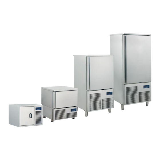
- Page 1 Instructions for use ALEXANDER 2/3-5-10-15 T Blast chiller Made in Italy www.studio-54.it...
-
Page 2: Table Of Contents
INDEX ISTRUCTIONS FOR USE 1. Foreword 2. Introduction 3. Preliminary checks 4. Elementary safety measures 5. Characteristics 6. Preliminary checks 7. Warranty terms 8. Installation 8.1. Positioning 8.2 Ambient 8.3 Cleaning and maintenance Electric wire substitution 9. Troubleshooting 10. Correct disposal 11. -
Page 3: Istructions For Use
ISTRUCTIONS FOR USE 1. Foreword Thank you for having chosen one of our products, the result of technological expertise and continuous search for a superior product in terms of safety, reliability and performance. This manual contains all the information and advice in order to operate with maximum safety and efficiency. -
Page 4: Warranty Terms
7. Warranty terms This product is covered by a 12 months warranty starting from the date of the purchase, except for the electrical components. The spare parts will be eventually supplied under warranty ex works our warehouse. Before the delivery of spare parts under warranty, there must be the returning of the damaged goods. The producing company declines any responsibility in case of improper use of the appliance. -
Page 5: Electric Wire Substitution
In order to make ad adequate maintenance of the appliance, the user, the maintenance man or the non- specialized staff must firstly keep in mind the elementary safety rules quoted on paragraph n. 1 GENERAL INFORMATION. Then, it is also compulsory to not remove the safety devices and the protections during the routine maintenance. -
Page 6: Use Advices
Business users should contact their supplier and check the terms and conditions of the purchase contract. This product should not be mixed with other commercial wastes for disposal. Some economic sanctions to the defaulting user are provided for wrong wasting of the products with RAEE mark. -
Page 7: Ce Plate
CE PLATE 1 Model 6 Mixture of insulating 11 Electric current 2 Voltage 7 Total power 12 Lighting power 3 Evaporation power 8 Date of manufacture 13 Category 4 Defrost power 9 Serial number 5 Type and quantity of refrigerant 10 Frequency... -
Page 8: Wiring Scheme
WIRING SCHEME Alexander 2/3 MC: Compressor VC: Condenser fan VE: Evaporator fan 1 C: Condenser 2mf K1: Compressor relay K2: Defrosting relay K3: Evaporator fan relay K4: Heating resistance relay PB1: Room probe PB2: Pin probe PB3: Evaporat. probe PB4: Condensator probe... - Page 9 Alexander 5T MC: Compressor VC: Condenser fan VE: Evaporator fan 1 RL: Relé 30A C: Condenser 2mf K1: Compressor relay K2: Defrosting relay K3: Evaporator fan relay K4: Heating resistance relay PB1: Pin probe PB2: Cold room probe PB3: Condensator probe PB4: Evaporator probe SW2: Door micro switch...
- Page 10 Alexander 10T M1: Compressor M2: Condenser fan M3: Evaporator fan 1 M4: Evaporator fan 2 YVL: Liquid solenoid RES: Frame heating wire KM1: Compressor electromagnetic wsitch FR1: Termical relay compressor QF1: Nc thermic relay FU1: Compressor fuse FU2: L1 fuse FU3: Fuse KL1: Evaporator fan relay K1: Compressor relay...
- Page 11 Alexander 15T M1: Compressor M2: Condenser fan M3: Evaporator fan1 M4: Evaporator fan 2 - 3 YVL: Liquid solenoid RES: Frame heating wire R: Oil compressor heater KM1: Compressor electromagnetic switch FR1: Termical relay compressor QF1: Nc thermic relay FU1: Compressor fuse FU2: L1 fuse FU3: Fuse FU7: Compressor heater fuse...
-
Page 12: Technical Drawings
TECHNICAL DRAWINGS Alexander 2/3 Alexander 5T... - Page 13 Alexander 10T Alexander 15T...
-
Page 14: Display Use
DISPLAY USE THE CONTROL UNIT OPERATION AND REGULATION ARE DESCRIBED IN THE USER MANUAL OF THE CONTROL UNIT EVCO EVX8015 KEYS SYMBOL NAME Key INCREASE Key DECREASE Key DEFROSTING Key POWER ON/OFF/START CYCLE / CYCLE OFF Key DEEP FREEZING Key BLAST CHILLING Key HARD BLAST CHILLING / SOFT DEEP FREEZING Key Auxiliary... -
Page 15: Icons
ICONS SYMBOL NAME Icon DEEP FREEZING It flashes during the selection of the soft deep freezing and preservation cycle, it is on during the following deep freezing cycle. Icon CHILLING It flashes during the selection of the blast chilling and deep freezing cycle, it is on during the following deep freezing phase. -
Page 16: Deep Freezing Cycles
HOW TO START THE BLAST CHILLING / DEEP FREEZING CYCLES Hereafter the instructions to set and start the most common settings of the device. N.B. FOR A BETTER WORKABILITY OF THE DEVICE, REMEMBER TO CARRY OUT A MANUAL DEFROST AFTER 2-3 BLAST CHILLING CYCLES IN A ROW. THIS PROCEDURE TAKES PLACE KEEPING THE DOOR OPEN AND PUSHING THE DEFROSTING BUTTON. -
Page 17: Hard Time Chilling
During time chilling phase it is always possible to visualize the probe temperature pushing the CHILL button . In that way, screen will show for 5 seconds the probe temperature. In that way, screen will show for 5 seconds the probe temperature. Press the START button when you want to remove food from the blast chiller. -
Page 18: Alarms
ALARMS The following chart shows the meaning of the alarm codes. Code Meaning Alarm temperature blast chilling or temperature deep freezing not over within the maximum time Solutions: tiME check the value of parameters r5 and r6 and AA. Main consequences: the device will save the alarm. - Page 19 Overheated condenser alarm Solutions: check the condenser temperature check the value of parameter C6. Main consequences: the condenser fan will be turned on. Blocked condenser alarm Solutions: check the condenser temperature check the value of parameter C7. unplug the device and clean the condenser. Main consequences: if the error occurs during the stand-by, it won't be possible to select nor to start any working cycle...
-
Page 20: Errors
ERRORS The following table illustrates the meaning of the error codes Code Meaning Cabinet probe error. Solutions: - check the value of parameter P0 - check the integrity of the probe - check the device-probe connection - check the temperature of the cabinet. Main consequences: - if the error occurs during the “stand-by”... - Page 21 Condenser probe error. Solutions: - the same as the cabinet probe error (“Pr1” code) but relative to the condenser probe. Main consequences: - the condenser fan will operate parallel to the compressor - the overheated condenser alarm (“COH” code) will never be activated - the compressor blocked alarm (“CSd”...
- Page 23 NOTES...
- Page 24 Studio-54 S.r.l. via Gian Lorenzo Bernini 147, Z.I. Paviola 3 35010 S. Giorgio in Bosco (Pd) Italy T. +39 049 9450466 F. +39 049 9451044 www.studio-54.it info@studio-54.it...
Need help?
Do you have a question about the Alexander 2/3 and is the answer not in the manual?
Questions and answers