Table of Contents
Advertisement
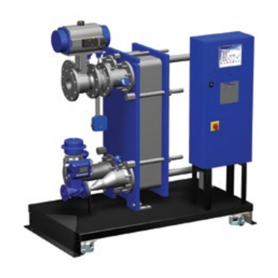
Spirax EasiHeat
HTG Heating System
TM
Compact Heat Transfer Solution
Installation and Maintenance Instructions
IM-P481-03-US
September 2017
1. Safety information
2. General product
information
3. Installation
4. Commissioning
5. Operation
6. Maintenance
© Copyright 2017
IM-P481-03-US 9/2017
1
Printed in USA
Advertisement
Table of Contents

Related Manuals for Spirax Sarco EasiHeat HTG

Summary of Contents for Spirax Sarco EasiHeat HTG
- Page 1 Spirax EasiHeat HTG Heating System Compact Heat Transfer Solution Installation and Maintenance Instructions IM-P481-03-US September 2017 1. Safety information 2. General product information 3. Installation 4. Commissioning 5. Operation 6. Maintenance © Copyright 2017 IM-P481-03-US 9/2017 Printed in USA...
-
Page 2: All Rights Reserved
Copyright © Spirax-Sarco Limited 2017 All rights reserved Spirax-Sarco Limited grants the legal user of this product (or device) the right to use the Work(s) solely within the scope of the legitimate operation of the product (or device). No other right is granted under this licence. In particular and without prejudice to the generality of the foregoing, the Work(s) may not be used, sold, licensed, transferred, copied or reproduced in whole or in part or in any manner or form other than as expressly granted here without the prior written consent of Spirax-Sarco Limited. -
Page 3: Safety Information
To the fullest extent legally permitted, Spirax Sarco excludes all responsibility and liability for any and all loss or damage caused in the event that the practices and procedures detailed in this document have not been followed. -
Page 4: Intended Use
The product has been specifically designed for use on steam, air or water/condensate. The products’ use on other fluids may be possible but, if this is contemplated, Spirax Sarco should be contacted to confirm the suitability of the product for the application being considered. - Page 5 1.9 Tools and consumables Before starting work ensure that you have suitable tools and / or consumables available. Use only genuine Spirax Sarco replacement parts. 1.10 Protective clothing Consider whether you and / or others in the vicinity require any protective clothing to protect against the hazards of, for example, chemicals, high / low temperature, radiation, noise, falling objects, and dangers to eyes and face.
-
Page 6: General Product Information
2. General product information 2.1 General information The Spirax EasiHeat™ HTG (Heating) incorporating S.I.M.S technology is a complete, compact and ready-to-use steam to water heat transfer solution that delivers superior energy efficient performance. It has been designed for applications with stable load conditions such as closed circuit heating applications. - Page 7 2.2 Spirax EasiHeat™ HTG nomenclature The product nomenclature is a reflection of the core items and unit options that have been ordered and supplied – See the table below: Spirax EasiHeat™ HTG nomenclature example: EHHCC Spirax EasiHeat™ Heating Condensate Control nomenclature Building Heating Spirax EasiHeat™...
-
Page 8: Installation
The installation of an appropriately sized safety valve, to protect any lower pressured equipment on either the hot or cold side of the plate heat exchanger, is strongly recommended. Spirax Sarco supplies a range of traps, strainers, separators, safety valves and pressure reducing equipment. 3.2 Air supply If a pneumatic control system is installed, connect a compressed air supply (4.5 to 8 bar g... -
Page 9: Electrical Specifications
3.4 Electrical specifications Electrical supply: Refer to the name-plate on the unit 110 Vac / 60 Hz Control panel supply voltage 240 Vac / 50 Hz Control panel load requirements Internally fused at 5 amps 24 Vac Electrical control actuator 4 - 20 mA control Pneumatic control actuator 4 - 20 mA control... -
Page 10: Terminal Designation
Remote operation and retransmission connections Terminal designation Description Type Remote set point 4-20 mA input Remote enable 24 Vdc signal Retransmission value 4-20 mA output 001- 001+ 24.3 CHANNEL 13 REMOTE SYSTEM CHANNEL 0 4-20 mA ENABLE RETRANSMISSION REMOTE PID OF PV OR VALVE Fig. - Page 11 Terminal layout overview X1 - X5 X6 - X8 X9 - X10A X10B - X10G PT100 4 - 20 mA 4 - 20 mA actuator Bypass inputs inputs outputs signals pump X13A-C X14 - X16 Bypass High limit volt free remote valve valve...
- Page 12 4. Commissioning We recommend that you use the service and support of a Spirax Sarco commissioning engineer. Details of this service can be found by contacting Spirax Sarco. Note: Pre commissioning requirements: In most new installations, dirt collects in the steam pipeline during construction of the system.
- Page 13 Open the secondary (cold side) isolating valves downstream of the Spirax EasiHeat™. Start the main secondary water circulating pump(s) if fitted. Check and confirm there is secondary water circulation through the Spirax EasiHeat™. If the circulation is okay, switch on the main power to the control panel (local isolator). Turn the control panel isolation switch to 'ON'.
- Page 14 4.2.1 TVA flowmeter commissioning chart To navigate around the first level menu use the up and down arrows, to enter any sub menu use the right arrow. Fig. 10 TVA configuration displays Normal run mode Default = 7452 Configuration but user display sequence sub-menus settable.
- Page 15 From the Basic DATA menu navigate to OUTPUTS and press the right arrow to enter the sub menu of 4 - 20 mA. 4-20 mA PUTS Fig. 11 PULSE The next menu Sorce will need FLOW to be selected. Obtain the correct flow data from the Spirax EasiHeat™ specification sheet supplied for accuracy, thereafter navigate down the menu and input: - Minimum flow = 4 mA Maximum flow = 20 mA...
- Page 16 4.3 HMI quick start commissioning procedure: The HMI display is a 7" touch screen, and the following procedures detail a basic set-up of the control system from initial power up. A more detailed description of each individual feature can be found in the full operation and maintenance manual. Fig.
- Page 17 Fig. 15 After unlocking the system (by using the unlock code) and setting the time and date or if the unit has been returned to factory default one of the following four pages will appear (pre-configured for designated region): Fig. 17 Fig.
- Page 18 The next screen (Figure 20) requires confirmation of the system to be configured: Fig. 20 Based on the selection of a HTG system the selection will be confirmed by the icon becoming highlighted with a blue surround and a continue button will appear. Press the continue button to advance to the system configuration menu.
- Page 19 The system configuration is now required to be entered on this page; again a selection is highlighted by a blue surround around the icon. Fig. 21 The system configuration should match the mechanical configuration of the Spirax EasiHeat™ and control system of the plant, correct configuration will show or hide options that are available after configuration.
- Page 20 Spirax EasiHeat™ mechanical and control system configuration options continued: Fig. 24 Linear actuator selection Electrical Pneumatic Fig. 25 Linear actuator control signals No position Position feedback feedback Fig. 26 Enable control selection Local Remote BACnet Fig. 27 PID set point (Outside weather compensation) Local Fig.
- Page 21 TVA not installed and no outside weather compensation selected If the Spirax EasiHeat™ unit is not fitted with a TVA flowmeter then the system configurations are now complete and the continue navigation button at the bottom right of the screen can be used to navigate to the next page which is the Start Page (with the blue hand).
- Page 22 A continue button will appear after system configuration which will navigate to the logged energy data for the Spirax EasiHeat™ system, press the continue button to navigate to the energy set-up page. Fig. 32 Accurately enter specific energy data to ensure valid energy data can be calculated. Boiler fuel properties - Selected via the drop down menu Boiler feedwater temperature Boiler efficiency...
- Page 23 In addition enter the custom fuel set points by selecting the custom fuel type. Fig. 33 Custom fuel parameters to be set: Fuel calorific value Fuel specific gravity Fuel emission factor Fuel conversion heat factor Energy setting will not affect control process, to obtain correct values of the calculated energy, the accurate data settings are essential.
- Page 24 4.4 Global navigation buttons Home PID set Settings Alarms Trend Service Energy mimic points menu menu menu menu logging 4.4.1 Home mimic This button will always navigate you back to the overview of the Spirax EasiHeat™ system that has been selected and configured. From this home screen the overall status and control of the Spirax EasiHeat™...
- Page 25 Fig. 35 V1 dialog page contains two value fields, the top one show the actual control valve position, and the lower one can be used to move the valve to requested position in manual mode. Manual Mode Automatic Mode The light indicator shows what mode is selected. IM-P481-03-US 9/2017...
- Page 26 PID set point This pop-up menu allows the entry of the Spirax EasiHeat™ system target PID set point and the associated ramp-up and ramp-down time bases. Fig. 36 Local temperature set point Outside weather compensation set points (Outside weather compensation only) Ramp-up temperature set point Ramp-down temperature set point BACnet temperature set point override with local temperature set...
-
Page 27: Enable Control
Enable control This pop-up menu depending on the configuration, allows the user to select one of three control modes for the Spirax EasiHeat™ or view the remote or BACnet enable status. If the configuration were set to BACnet, it is possible to override the configuration and change it to local enable configuration. - Page 28 Zoom The zoom pop-up provides a more detailed view of the key process parameters. 179.6°F 71.06°F 72.68°F Fig. 38 IM-P481-03-US 9/2017...
- Page 29 4.4.2 PID set points This page allows you to set the PID control factors (entries available only for engineers). Fig. 39 Proportional band (P factor of the PID control) Proportional gain (P factor of the PID control) Integral factor (I factor of the PID control) Derivative factor (D factor of the PID control) Desired value (local, remote or BACnet set point) IM-P481-03-US 9/2017...
- Page 30 Current value of the controlled variable (T2 temperature) Manipulated value (valve position request) PID real time trend page (Allows to configure the PID set points with view of the actual signals) Outside weather compensation set points page (Outside weather compensation only) The following screen is accessible from PID Loop Set Points page (available only for engineers).
- Page 31 The following page allows the outside weather compensation set points to be input. This can be accessed from PID Loop Set Point Page or from Set Points Dialog Page only for engineer level users. Fig. 41 IM-P481-03-US 9/2017...
-
Page 32: Settings Menu
4.4.3 Settings menu The settings displayed (with blue surround) are default settings after the country flag has been selected, changes can be made if required. Fig. 42 Time / date configuration page Language selection page Temperature units selection Flowmeter units selection (Energy monitoring only) Energy units selection (Energy monitoring only) IM-P481-03-US 9/2017... - Page 33 There is also the possibility of changing the language (from the pre-configured options) by using the following selection menu without affecting the engineering units: Fig. 43 In addition, engineers are able to set or change the actual time and date for PLC and HMI. Fig.
-
Page 34: Alarms Menu
4.4.4 Alarms menu The following page shows all active alarms, an active alarm is indicated on all the mimic screens via the alarm bell in the top left hand corner of the screen. Fig. 45 There are also navigations to further alarm set point pages as well as the historical alarm list, located on the right of the display. - Page 35 Band alarm Band alarm temperature set point Band alarm delay time set point Band alarm reset time set point Differential alarm (HTG only) Temperature differential alarm set point Temperature hysteresis set point Reset high-limit alarm latch Historical alarm page (PLC controlled high-limit only) IM-P481-03-US 9/2017...
- Page 36 Following page provides access to historical alarm list. This allows the user to view previously triggered alarms. Fig. 46 Alarms indication icon Manual alarm indication icon Caution - high-limit setting: • If fitted, the high-limit controller should be set at a suitable level to protect plant, process and personnel.
-
Page 37: Trend Menu
4.4.5 Trend menu This menu provides historical trend monitoring of the process values, useful for analysing the historical reactions of the Spirax EasiHeat™ system to process conditions. Fig. 47 Energy trend page button (energy monitoring only) Flow trend page button (energy monitoring only) Temperature trend PID process trend page button... -
Page 38: Service Menu
4.4.6 Service menu The following page provides service information and allows engineering level users to navigate to pages containing process information. Fig. 48 Save trends to USB memory stick This LED if green confirms that the memory stick is connected and the data format is correct (FAT32 only allowed). - Page 39 Next service due at number of hours Process enable event count High-limit event count Local Spirax Sarco engineer contact details dialog page Hardware monitoring pages (input / output overview) IM-P481-03-US 9/2017...
-
Page 40: Hardware Monitoring
4.4.7 Hardware monitoring The following pages provide only an overview of the input and outputs; it is not possible to set any set points. Fig. 49 Fig. 50 Fig. 51 Figures 50, 51, 52 and 53 display the analogue input and output values. Fig. - Page 41 Local Spirax Sarco engineer contact details dialog page Please Contact your local Spirax Sarco, Inc representative via the web at www.spiraxsarco.com/global/us Fig. 54 Spirax Sarco, Inc 1-800-883-4411 4.4.8 Energy logging Energy monitoring pages provide the user access to view the total value of the power and carbon use, total of CO emission and calculated total cost of energy that has been used.
- Page 42 Energy monitoring set points At engineer level it is possible to access the energy page to make changes by pressing the energy monitoring set point. This will go to the energy page. Fig. 56 To finalise the mechanical commissioning of the system: Open all condensate drain valves.
-
Page 43: Fault Finding
Scaling value incorrect TVA commissoining match those on TVA input is not the HMI (this data is found on the showing correctly Spirax Sarco engineers 4-20 mA page) Polarity of 4-20 mA Reverse polarity and wire as per incorrect electrical drawings... -
Page 44: Maintenance
6. Maintenance Note: Before actioning any maintenance observe the 'Safety information' in Section 1. 6.1 General For maintenance of the individual components that make up the system, please see the relevant product specific IMI’s for the components concerned. 6.2 High-limit device testing The purpose of the test is to ensure that the system operates satisfactorily when required to do so. - Page 45 IM-P481-03-US 9/2017...
- Page 46 Spirax Sarco Applications Engineering Department Toll Free at: 1-800-883-4411 SPIRAX SARCO, INC. 1150 NORTHPOINT BLVD. • BLYTHEWOOD, SC 29016 PHONE 803-714-2000 FAX 803-714-2222 www.spiraxsarco.com/global/us IM-P481-03-US 9/2017...
Need help?
Do you have a question about the EasiHeat HTG and is the answer not in the manual?
Questions and answers