
Summary of Contents for GPI PRO SLED II
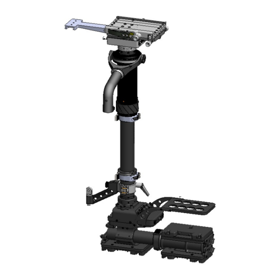
- Page 3 FIGURE 1: DB-III Upper Junction box VZ Gimbal VZ Gimbal Grip Center Post II Recorder Mount Monitor Arm Gen 3 Battery Rack Lower Junction Box...
- Page 4 FIGURE 2: Safety Lever Locking Screw Fore/Aft Control Knob This third generation camera-mounting platform offers the following: “Cross Roller Bearings” which, by their line contact, as opposed to the point contact of ball bearings, and their increased length of engagement, multiply the stiffness of the D-Box III, and allow smooth easy movement fore/aft and side/side.
- Page 5 FIGURE 3: Clamp Block 8-32 Mounting Screws Clamp Lever Fore/Aft Control Knob Side/Side Control Knob Lubrication: Apply lubrication to the locking screw, and the bearings as dictated by shooting conditions. Cleaning: Wipe down the visible areas with a light solvent. Tightening: Do not over-tighten the locking screw, this will defeat the function of the clamp lever.
- Page 6 Tension Adjustments: In order to adjust the tension or resistance in the knobs it is necessary to use the D-Box III tool. side/side adjustments it is necessary to first remove the side/side knob on the left side of the D- Box.
- Page 7 THIRD GENERATION: UPPER JUNCTION BOX Overall, the upper junction box delivers power to the camera, the focus system and the video tap via your cables. It is attached directly under the Donkey Box. Figure 1: UPPER JUNCTION BOX (front view) Provides 12/24vdc Provides 12vdc and BNC Connector...
- Page 8 The PRO™ Gimbal’s design and construction guarantee a precise intersection of all three axes, while the correct application of bearings provides a smooth, deflection-free pan, roll and tilt. A locking mechanism achieves concentric clamping about the post, ensuring that all axes converge at post center.
- Page 9 The Generation II system makes use of a quick connect/disconnect assembly at each end of the post. Inside the post is a coiled cable consisting of (18) conductors all of which are terminated at each end by a LEMO EGG.3B.856.CLM3 connector. The Generation II Center post does away with the slotted inner post of the Generation I model.
- Page 10 Located at the top center of the Lower Junction Box is a large 18-pin Lemo jack which provides the electrical connection point for the Center post Assembly. The Center post Assembly is attached to the Lower Junction Box as follows: 1.
- Page 11 The Monitor Arm is normally clamped about the spacer, but can also be clamped about the outer post. A Kipp handle and a swing arm are used to loosen/tighten the monitor arm clamp about the post. For quick inversion of the monitor, loosen the thumb screw, twist the monitor arm 180 degrees and re-tighten the thumb screw.
- Page 12 The third generation Lower Junction Box (attached directly above the Battery Rack) has been re- designed to ensure even greater It’s purpose is to distribute 12 or 24 volt power from each Battery in the battery rack to respective destinations throughout the sled, namely to: Camera, Monitor, Video Tap, Video Transmitter, Wireless Lens Control System, On-Board Recorder and Accessories.
- Page 13 THIRD GENERATION: LOWER JUNCTION BOX REAR VIEW 10 amp Breaker 5 amp Breaker BNC Connector BNC Connector Analog Lemo 0B304 Lemo 0B305 12vdc and video Regulated 9vdc signal Recorder power Record/Play back switch Lemo 3B.856 12/24 Safety switch Lemo 1B308 12vdc and video signal...
- Page 14 BATTERY MOUNTING SYSTEM (Gen III and Gen IV) The PRO™ Gen III Battery Mounting System consists of a tough, tubular structure. The Battery System incorporates three removable mounting brackets for batteries and is attached to the Lower Junction Box. The Battery Rack can also house accessories such as an electronic level sensor, video recorder and video transmitter.
- Page 15 FIGURE 18: Legend: A - Auxiliary Battery C - Camera Battery M - Monitor Battery Three Batteries: This is the "standard" configuration of the PRO™ Sled. It should be used with 24-volt camera systems where a separate monitor battery is desired. In this configuration: 1.
- Page 16 1. Whenever possible, turn off Gyros when not in use to save battery power and to limit heat buildup in the gyro. 2. The inverter can be powered by 12 or 24 volt block batteries, for either gyro spin-up prior to use or continual use during a shot.
- Page 17 Spring tension adjustment is accomplished by inserting the Gimbal wrench (5/32”) through the guide hole at the end of the cartridge and engaging the lead screw. Clockwise rotation of the wrench effects an increase in the spring tension, counterclockwise a decrease. This adjustment can be accomplished: a.
- Page 19 Titan and Atlas Arm Orientation Orientation of the socket block adapter assembly is critical in that, the Arm should never be mounted in such a way that the weight is applied parallel to the axis. This incorrect axis orientation is always present when using back mounted vests.
- Page 20 Incorrect Correct Left Side Mount Correct Right...
- Page 22 Gimbal Post: The Gimbal post rides on a bearing, reducing the friction between the Arm and the post. The Gimbal Post Clamp can be adjusted with a 5/32 Allen wrench for the desired drag. Reversing the Socket Block Adapter Assembly: Using the two supplied Arm wrenches (located in the lid pocket of the Arm case), remove one of the two vertical pin caps holding the Socket Block Adapter Assembly on to the arm.
- Page 24 Gimbal Post: The Gimbal post rides on a bearing, reducing the friction between the arm and the post. The Gimbal Post Clamp can be adjusted with a 5/32 Allen wrench for the desired drag. Reversing the Socket Block Adapter Assembly: Using the two supplied arm wrenches (located in the lid pocket of the arm case), remove one of the two vertical pin caps holding the Socket Block Adapter Assembly on to the arm.
- Page 26 PIN OUT CHART: UPPER JUNCTION BOX Lemo 1S.303 Lemo 0S.304 1. 24vdc 1. 12vdc 2. Gnd 2. NC 3. 12vdc 3. Gnd 4. 24vdc Front Lemo 0B.304 Lemo 1S.303 Lemo 1S.302 1. Gnd 2. 12vdc 1. 24vdc 1. 12vdc 2. Gnd 3.
- Page 27 This section is designed to act as an aid in the unlikely event of system failure. Contrary to popular belief, one does not have to be a technical wizard in order to troubleshoot and repair one’s system. The key to troubleshooting lies in the ability to identify the problem, and once this is accomplished, correcting the problem is usually fairly simple.
Need help?
Do you have a question about the PRO SLED II and is the answer not in the manual?
Questions and answers