Table of Contents
Advertisement
Via delle MELE, 65
47522 Cesena (FC) ITALIA
Tel.: 0547-418611
Fax.: 0547-418612
COSTRUZIONI
MECCANICHE
BSS-134
AUTOMATIC VERT-BAG PACKAGING MACHINE
Operating instructions
Manuale istruzioni
Mode d'emploi
Manual de instrucciones
Gebrauchshandbuch
serial number:
Data di redazione
Codice di identifi cazione
Note
•
original instructions
07/13
BSS/STD-02 GBR
(C.P.)
Advertisement
Table of Contents

Related Manuals for Sorma BSS-134

Summary of Contents for Sorma BSS-134
- Page 1 Via delle MELE, 65 47522 Cesena (FC) ITALIA Tel.: 0547-418611 Fax.: 0547-418612 COSTRUZIONI MECCANICHE BSS-134 AUTOMATIC VERT-BAG PACKAGING MACHINE Operating instructions Manuale istruzioni Mode d'emploi Manual de instrucciones Gebrauchshandbuch serial number: Data di redazione Codice di identifi cazione Note •...
-
Page 2: General Informations
1.3 Confi dentialy The technical information contained in this manual is the property of Sorma S.p.A. and is strictly con- fi dential: disclosure or copying (even partial) of such information is therefore forbidden unless written authorization has been obtained from Sorma S.p.A.. Using the manual for any purpose not strictly... - Page 3 BSS-134 CHAP.- 1 GENERAL INFORMATIONS 1.4 Warnings The warnings, with instructions on risk-identifi cation procedures, are highlighted by the symbols shown below. Do not underestimate their importance: machine damage and operator injury are real possibilities. DANGER = This symbol informs that the non-compliance with the indications can cause damages to the equipment and can jeopardise the safety of persons.
- Page 4 BSS-134 CHAP.- 1 GENERAL INFORMATIONS 1.6 Request for intervention - technical assistance Should the intervention of the Clients After-Sales Technical Assistance Service be required, contact Sorma S.p.A. at the following address: Sorma S.p.A. technical assistance Tel. 0547/418611 Fax. 0547/418612 e~mail: sorma@sormaitalia.com specifying: 1.
-
Page 5: Dichiarazione Ce Di Conformità
SORMA S.p.A. Azienda Via delle Mele, 65 47522 Indirizzo Provincia Cesena Italia Città Stato DICHIARA CHE LA MACCHINA BSS-134 Insacchettatrice mod. BSS-134 Descrizione Modello 2012 05/2012 xxxxxx Serie/Matricola Anno costr. Revisione Insacchettatrice mod. BSS-134 Denominazione commerciale È CONFORME ALLE DIRETTIVE Direttiva 2006/42/CE del Parlamento Europeo e del Consiglio del 17 maggio 2006 relativa alle macchine e che modifica la direttiva 95/16/CE. -
Page 6: Technical Specifications
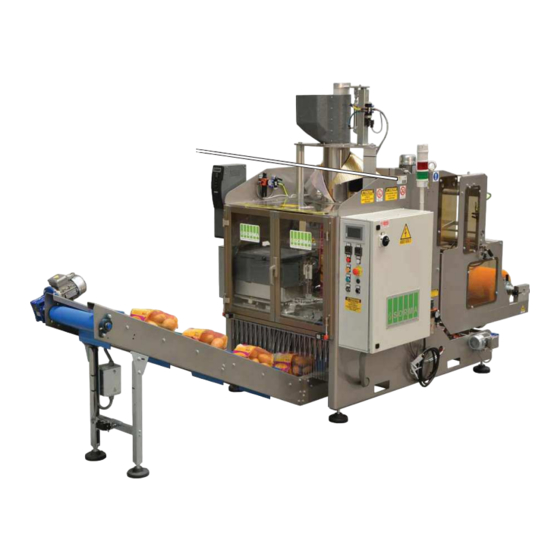
2/2,5 to 3 kg.: tube diam. 180 and 203 mm. The BSS-134 must be used only for the purpose it was expressly designed for. Any other use is to be deemed improper and hence unreasonable. The company Sorma S.p.A. shall not be held liable for any damage due to improper, mistaken or unreasonable use of the machine, that may be caused to persons and/or animals and/or things. - Page 7 BSS-134 CHAP.- 2 TECHNICAL SPECIFICATIONS 2.4 Machine description The machine basically consists of: A = Electrowelded frame B = Loading hopper C = Intake D = Loading tube E = Carrier tracks F = Vertical sealing unit G = Horizontal sealing unit H = Tensioner rollers unit I = Air fi...
- Page 8 BSS-134 CHAP.- 2 TECHNICAL SPECIFICATIONS 2.5 Notes on using the machine IT IS FORBIDDEN TO: 1. Amend the cycle of the machine; 2. Work different products from those indicated; 3. Replace or amend the speed of the machine components; 4. Replace pieces with non-original spare parts;...
- Page 9 BSS-134 CHAP.- 2 TECHNICAL SPECIFICATIONS 2.7 Overall dimensions Fig.2 chap.2...
-
Page 10: For Maintenance
BSS-134 CHAP.- 3 I.P.D. FOR MAINTENANCE 3.1 Individual protection device The person in charge must inform staff on the following matters concerning the safety in using the machine: Risks due to injury; Devices prepared for the safety of the operator;... - Page 11 BSS-134 CHAP.- 3 I.P.D. FOR MAINTENANCE 3.1.1.3 Light gloves (protection of hands) They must be suitable for the hand of the operator that must wear them and must be suffi ciently long to cover the elastic clothing around the wrist of the operator.
-
Page 12: Machine Safety
- Any attempt to dismantle, modify or tamper with any part of the machine will invalidate the warranty, and Sorma S.p.A. will be held harmless for any damage to people or things due to such abuse. - The assistant operator must possess all the psychological and physical requirements and capacities needed for using the machine. - Page 13 BSS-134 CHAP.- 4 MACHINE SAFETY - Never stand on the machine. - Never leave the machine or installation unguarded while it is running. - Notify the maintenance staff of any operational anomaly on special devices. - Avoid working on the machine while wearing objects which may cause accidents (watch, tie, bra- celet, ring etc.).
- Page 14 - For any eventual problem that should arise during the operational life-span of the machine and, however, not contemplated in this technical documentation, contact the Clients After-Sales Technical Assistance Service Sorma S.p.A., in order to solve the problem in the least time possible. - Daily check the correct functioning of all switches and safety devices.
- Page 15 - EXTERNAL TECHNICIAN: qualifi ed technician made available by the producer or distributor, able to intervene for amendments, repairs or replacements. - TECHNICIAN Sorma S.p.A.: qualifi ed technician made available by Sorma S.p.A. or by its agent to perform complex operations, installation and start-up.
- Page 16 BSS-134 CHAP.- 4 MACHINE SAFETY 4.5 Safety Pictograms...
- Page 17 BSS-134 CHAP.- 4 MACHINE SAFETY...
- Page 18 BSS-134 CHAP.- 4 MACHINE SAFETY pos. Safety Pictograms pos. Safety Pictograms...
- Page 19 BSS-134 CHAP.- 4 MACHINE SAFETY 4.6 Residual risks The machine has been designed and realised with the opportune warnings in order to guarantee the safety of the user. However, there are residue risks which are reported below. All personnel in charge of operating and conducting maintenance work on the machine, as well as staff working near it, must be aware of the following risks.
- Page 20 5.2 Shipping and lifting BSS-134 is sent with a cover made of one or more sheets of cellophane adhering. The machine, when shipped by Sorma S.p.A. with the purpose of reducing its size for shipping, is partially dismantled. Upon receipt of the machine, check there are no visual damages; on the contrary immediately inform Sorma S.p.A.
- Page 21 - Avoid any sudden movements which could damage the machine. The BSS-134 or any parts of the same must be handled only using the most suitable media: self- moving fork lift truck; bridge crane, having a suitable capacity for the actual weight of the machine.
-
Page 22: Installation
Environmental conditions different from those specifi ed can cause serious damages to the machine and, in particular, to the electronic equipment, therefore for different environmental conditions, the client must inform Sorma S.p.A. to evaluate the possibility of applying adequate systems to the machine to guarantee the good functioning. - Page 23 BSS-134 CHAP.- 6 INSTALLATION blue Fig.2 chap.6 The power and compressed air supply cables should be brought close to the machine with appropriate sheaths or channels, not to cause any obstacle for the operators and to properly protect them at the same time.
- Page 24 BSS-134 CHAP.- 6 INSTALLATION 6.5 Proper machine running direction check Once the connection to the power mains and to the compressed air system is done, proceed as follows: 1) Set the [10] main switch (see fi g.4 chap.6) to [ON].
- Page 25 BSS-134 CHAP.- 6 INSTALLATION 6.6 Safety devices 6.6.1 Mobile protections that can be opened The mobile protections are provided with safety micro switch (see fi g.8 chap.6) that intervene at every opening of the protection, activating the emergency stop. Do not eliminate the safety micro switch function with electric or mechanical amendments.
-
Page 26: Start-Up And Stop
BSS-134 CHAP.- 7 START-UP AND STOP 7.1 Machine start-up - Check that the mobile protections, provided with safety micro switch, are closed correctly, - Set the [10] main switch (see fi g.1 chap.7) to the [ON] position, - Verify that all components are in phase (coil unit, fi lm, etc.) and there are no obstructing conditions and/or hazardous conditions for machine operation, - Press the orange MANUAL RUN [7] button (see fi... - Page 27 BSS-134 CHAP.- 7 START-UP AND STOP 7.5 Stopping the machine in the event of an injury or failure It is absolutely necessary to: 1) disconnect the power supply by using the designated main switch in the front of the electric control board (setting it to [OFF]) and block the switch with a padlock (see fi g.2 chap.7) whose key is held only by qualifi...
-
Page 28: Electric Panel
BSS-134 CHAP.- 8 ELECTRIC PANEL 8.1.1 Electrical panel control board Danger of death. For safety reasons, the electric control board must remain permanently closed. The electric control board can only be opened by authorised staff. The ventilator fi lters of the electric control board must be replaced regularly (if present). -
Page 29: Red Light
BSS-134 CHAP.- 8 ELECTRIC PANEL - [1] Black Push Button - PLIERS HORIZONTAL - this push button only works when the machine is set to manual working and when pressed at the same time as push button [7] MANUAL WORKING. - Page 30 BSS-134 CHAP.- 8 ELECTRIC PANEL - [5] VERTICAL SEALING - It adjusts the sealing temperature to the type of material used and the current room temperature. The recommended temperature ranges from 240 to 280°C. The machine is READY FOR USE when the thermoregulator displays the temperature that was previously set.
- Page 31 BSS-134 CHAP.- 8 ELECTRIC PANEL - [6] Luminous green button - AUTOMATIC WORKING - this button puts the machine into automatic working. The green light indicates that the machine has been put into the automatic mode. - [7] Luminous red button - MANUAL WORKING - this button puts the machine into manual work- ing.
- Page 32 BSS-134 CHAP.- 8 ELECTRIC PANEL - [10] MAIN SWITCH - Enables/disables the machine power supply. [OFF] = no power supply to the panel. [ON] = panel powered up. - [11] BLACK BUTTON – SPLICE SEALING (on the side opposite the manual controls) this button works only if the machine is in manual start mode;...
- Page 33 BSS-134 CHAP.- 8 ELECTRIC PANEL - [13] TERMINAL (TOUCH SCREEN DISPLAY) Use the terminal to: - 1) Carry out any manual operation of each specifi c machine part (with machine in MANUAL RUN- NING mode) from page 5 to page 9.
- Page 34 BSS-134 CHAP.- 8 ELECTRIC PANEL Tabella 1.1: Messagge FAULTY MESSAGGI SUL DISPLAY NOTE R05_INPUT_X5, MARKS READER FAULTY Carry out the procedure to place the fi lm back into position (see fi led F3 and F4 on page 9 of the display).
- Page 35 F2 AUTOMATIC RUN = select one program, set up and display the working conditions relative to the program selected. F3 MACCHINE CONFIGURATION = set up the machine. F4 TIMER/COUNTER SETTING = set up the machine cycle time values. F5 SORMA = only for the SORMA technicial support.
- Page 36 BSS-134 CHAP.- 8 ELECTRIC PANEL If you press , you will access page 03. Here you can select F1, F2, F3, F4, F5 to choose the language you want: (N.B. = not all languages are actived). If you press on page 03 or F1 on page 02 (BASIC MENU), you will access page 05: F1 = closure of the horizontal gripper = it is conducted by closing the horizontal gripper.
- Page 37 By pressing from page 6, page 7 will appear F1 = hopper band = the band of the motorised hopper starts (when BSS-134 is fi tted with a motorised hopper). F2 = elevator conveyor belt = the elevator conveyor belt is run.
- Page 38 BSS-134 CHAP.- 8 ELECTRIC PANEL By pressing from page 7, page 8 will appear F1 = stick label = you can make the printing piston move forward so that it applies a stick-on label (if any) on the fi lm.
- Page 39 F2 DEFAULT DATA = this push-button is enabled only with the machine in manual running mode. It is used to reset counts or times (see pages from 41 to 44) back to the dafault values which are set on the new machine by SORMA. For doing it, proceed as follows: 1) Press F2 and, by keeping it pressed, press the red mushroom-shaped [3] STOP button (see fi...
- Page 40 BSS-134 CHAP.- 8 ELECTRIC PANEL By pressing from page 9, page 20 will appear fi eld A fi eld B fi eld C PR.NR.: = editable symbolic fi eld to choose the work program among the various pre-set programs. This setting must be conducted when the machine is not in automatic start mode. There are 12 operating programs.
- Page 41 BSS-134 CHAP.- 8 ELECTRIC PANEL Creation of a recipe (procedure to conduct with the machine not in automatic start) 1) set the parameters to the desired values All the parameters marked with the symbol below can be saved: 2) press to choose one of the 12 work cycles, 7 based on notches and 5 based on counts.
- Page 42 T87 Air Blast Horizontal = It is the time needed for the blower to cool the horizontal sealing. T88 TIME HOPPER RUN = It is the time needed for the hopper to move (if BSS-134 is equipped with a hopper).
- Page 43 BSS-134 CHAP.- 8 ELECTRIC PANEL By pressing from page 21, page 22 will appear fi eld A fi eld B 504 Request Discarge Anticipation (mm) = if the fi eld is 0, there is no advance unload request. if the fi eld is other than 0, the unload request is anticipated by "x" mm with respect to the end of the unwinding of the mesh/fi...
- Page 44 BSS-134 CHAP.- 8 ELECTRIC PANEL By pressing from page 22, page 23 will appear fi eld A fi eld B C/M: = It is the number of packages produced per minute. TOTAL: = It is the total number of packages produced by the machine since its start.
- Page 45 WHERE YOU ENABLE MACHINE CONFIGURATION PROCEDURES. N.B. = IT IS RECOMMENDED NOT TO APPLY NEW SETTINGS (AFTER THE INITIAL CONFIGURATION) UNLESS SORMA SERVICE SUGGESTS TO DO IT. F1 PRINTER [ON/OFF] = to select [ON] or [OFF] and enable / disable the printer.
- Page 46 BSS-134 CHAP.- 8 ELECTRIC PANEL By pressing from page 30, page 31 will appear F1 TEST CYCLE [OFF/ cinghioli aperti / cinghioli chiusi] = ONLY FOR TECHNICAL ASSISTANCE SORMA S.P.A. F2 R80 = free option. F3 R88 = free option.
- Page 47 By pressing from page 31, page 32 will appear F1 DOUBLE VERTICAL WELDING [ON/OFF] = If you select [ON], BSS-134 will withdraw a half pack- age and carry out a vertical sealing operation. Afterwards it will withdraw the remaining half package to produce a package, carry out a vertical sealing operation and end the current packaging cycle.
- Page 48 BSS-134 CHAP.- 8 ELECTRIC PANEL By pressing from page 32, page 41 will appear T89 DELAY CLOSED CLAM = it is a closing delay of the horizontal pliers after a withdrawal. T90 TIME FOLD = it is the time elapsing from when the blind bags are closed to when the pliers start closing.
- Page 49 BSS-134 CHAP.- 8 ELECTRIC PANEL By pressing from page 42, page 43 will appear 504 Request Discarge Anticipation (mmm) = see fi eld on page 22 of the display. 505 WHITE BAND (mm) = see fi eld on page 20 of the display.
- Page 50 The consumption materials are: - PAIRED NET AND FILM COILS = The BSS-134 can use two different kinds of coils of paired net and fi lm (depending on the kind of product being processed, and hence on the diameter of the loading tube).
- Page 52 BSS-134 CHAP.- 9 CONSUMPTION MATERIALS - Cut the net/fi lm by hand using a pair of scissors, making a diagonal cut of about 45° (see fi g.4 chap.9). - activate the manual valve [M] (see fi g.7 chap.9) to open the carrier tracks; drag the mesh manually and roll it up in the tube.
- Page 53 BSS-134 CHAP.- 9 CONSUMPTION MATERIALS - Put the drawing belts back in their right position using the handwheel [M] (see fi g.7 chap.9). Fig.7 chap.9 9.3 Label loading The machine can carry various (optional) electronic labelling devices. The instructions concerning how to load the various kinds of labels and how to programme their printing appear on the specifi...
- Page 54 BSS-134 CHAP.- 9 CONSUMPTION MATERIALS Fig.8 chap.9 9.5 Tube change for vertical sealing unit press [2] NET UNWINDING JOGGING STEP STOP IN PHASE with machine running in AUTOMATIC. press the red Mushroom-shaped button - STOP [3].
- Page 55 BSS-134 CHAP.- 9 CONSUMPTION MATERIALS lift the carter. manually cut the net/fi lm using scissors. bleed pressure from the pneumatic circuit by closing the slide valve [C].
- Page 56 BSS-134 CHAP.- 9 CONSUMPTION MATERIALS disconnect the pneumatic solenoid val- ve's reel. disconnect the air tube from the relative fi tting. loosen the hand wheels.
- Page 57 BSS-134 CHAP.- 9 CONSUMPTION MATERIALS remove the tube to be replaced. remove the tube to be replaced. remove the tube to be replaced.
- Page 58 BSS-134 CHAP.- 9 CONSUMPTION MATERIALS insert the tube to be used. insert the tube to be used. tighten the hand wheel.
- Page 59 BSS-134 CHAP.- 9 CONSUMPTION MATERIALS tighten the hand wheel. connect the pneumatic solenoid valve's reel. connect the air tube to the relative fi tting.
- Page 60 BSS-134 CHAP.- 9 CONSUMPTION MATERIALS lower the carter. press MANUAL START [7]. open the slide valve [C] to connect the pneumatic circuit.
- Page 61 BSS-134 CHAP.- 9 CONSUMPTION MATERIALS remove the net/fi lm reel to be replaced. load the net/fi lm reel.
-
Page 62: Danger Of Burns
Although the above concept is certainly valid, the BSS-134 needs little and easy maintenance. Obviously main- tenance operations should be carried out also at the end of the seasonal working cycle, after which the machine remains stopped for rather long periods. - Page 63 BSS-134 CHAP.- 10 MAITENANCE E CLEANING 10.2 Pictograms and inspection tables Tables have been set out for the carrying out of the requested inspection, showing the machine and certain of its parts, from which it is immediately possible to understand the type of requested check.
- Page 64 BSS-134 CHAP.- 10 MAITENANCE E CLEANING Cleaning check the cleaning state of the elements. Handling check, by handling, the functioning of the components (e.g.: friction test). It is compulsory to wear protection gloves when carrying out the handling operations. Lubrication check the lubrication state of the components.
- Page 65 BSS-134 CHAP.- 10 MAITENANCE E CLEANING LEGEND Chain Cogwheel Support Sucker Spring Motion rod Cylinder Sliding bar Pinion Sliding guide Toothed belt Ball runner blocks and guides Pulley Belt Belt Gearmotor...
- Page 66 BSS-134 CHAP.- 10 MAITENANCE E CLEANING Horizontal welding unit 160 h 160 h 160 h 160 h 160 h 160 h 160 h 160 h 160 h Vertical helding unit 160 h 160 h 160 h...
- Page 67 BSS-134 CHAP.- 10 MAITENANCE E CLEANING Dragging tracks kit 160 h 160 h 160 h 160 h 160 h 160 h 160 h 160 h 160 h 160 h 160 h 160 h 160 h 160 h 160 h 160 h...
- Page 68 BSS-134 CHAP.- 10 MAITENANCE E CLEANING Calibrator frame kit 160 h 160 h 160 h 160 h 160 h 160 h 160 h 160 h 160 h 160 h 160 h 160 h 160 h 160 h 160 h 160 h...
- Page 69 BSS-134 CHAP.- 10 MAITENANCE E CLEANING Tube kit 160 h 160 h 160 h 160 h 160 h 160 h...
- Page 70 BSS-134 CHAP.- 10 MAITENANCE E CLEANING 10.7 Routine and extraordinary maintenance The routine maintenance entails: 1) checking the functioning state of the various parts, 2) eliminating or correcting anomalies, even those that, despite not constituting immediate danger or technical bad service, can lead to inconveniences in case of their prolonging.
- Page 71 BSS-134 CHAP.- 10 MAITENANCE E CLEANING Cleaning of compressed air fi lter Loosen the cup containing the air fi lter. Remove the fi lter and clean it using compressed air. Assemble the fi lter again and tighten the cup. Check belts The belts and the chains must be periodically checked.
- Page 72 BSS-134 CHAP.- 10 MAITENANCE E CLEANING Inspect photocells WARNINGS: the intervention frequency very much depends on the environment in which the machine works; if particular dirty or dusty, frequency must be increased. This system requires an alignment of the two photocell and refl ector devices and, therefore, when these are not aligned or when a body is present between the two that cannot be crossed by the ray, the photocell is “engaged”...
- Page 73 BSS-134 CHAP.- 10 MAITENANCE E CLEANING 10.7.2 Extraordinary maintenance Chain transmission A chain transmission is used to transmit the movement between the two shafts of the same machine, as well as between an electric motor, or any other source of power, and an independent mechanism.
- Page 74 BSS-134 CHAP.- 10 MAITENANCE E CLEANING Assembly of the chain Before assembling the chain, ensure that the alignment of the shafts has been carried out correctly and that subsequent amendments have not occurred. Dismantle the joining handle and wrap the chain on to the teethed wheels, so that the two ends slot in the tooth bottom of one of the pinions.
- Page 75 BSS-134 CHAP.- 10 MAITENANCE E CLEANING Pinions The pinions are the toothed wheels on which the chains rotate, transmitting the movement. The life-span of a pinion is limited, it is therefore some times necessary to replace it. A pinion can be idle or motor.
- Page 76 BSS-134 CHAP.- 10 MAITENANCE E CLEANING Locking using the pins For a good fastening, and to facilitate future dismantling, make a hole on the shaft to host the point of the locking pin. Upon drilling, fi rstly remove the pin and position the unit on the shaft.
- Page 77 BSS-134 CHAP.- 10 MAITENANCE E CLEANING CLEANING THE SEALING PLIERS The sealing pliers should be cleaned at the end of every working day to ensure maximum life of the sealing unit and avoid incrustation deposits due to the melting of the plastic material which seeps in the cogs [A], the punches [B] ad the knife [C] of the sealing pliers [S.inf.] and [S.sup.].
- Page 78 BSS-134 CHAP.- 10 MAITENANCE E CLEANING 2) Wipe the Tefl on-coated area, the knife [C] and the punches [B] by means of a damp sponge. If necessary, use a plastic scraper taking care not to scratch the Tefl on coat.
- Page 79 BSS-134 CHAP.- 10 MAITENANCE E CLEANING 10.8 General procedure to be carried out at the end of maintenance Once maintenance is completed, connect the electric power supply and the pneumatic supply again and ensure that: 1) all safety devices are functioning;...
- Page 80 The activities described in this paragraph must be carried out only by qualifi ed staff, and precisely: - SORMA S.p.A. technician with the help of local labour; - trained technician who has attended specialisation and training courses and with experience with regard to installation, start-up and maintenance of the machine, and is aware of the accident-prevention Standards.
- Page 81 BSS-134 CHAP.- 11 RE-INSTALLATION AND DEMOLITION 11.3 Demolition and disposal of the machine The operations must be carried out by qualifi ed staff At the end of the machine’s life-span, to dismantle the same, remove the identifi cation serial number, the use manual and any layouts that have been kept with the disposal documents issued by the appropriate authorised companies.
Need help?
Do you have a question about the BSS-134 and is the answer not in the manual?
Questions and answers