Table of Contents
Advertisement
Quick Links
Advertisement
Table of Contents

Subscribe to Our Youtube Channel
Related Manuals for AGM COBRA Series

Summary of Contents for AGM COBRA Series
- Page 1 COBRA THERMAL IMAGING BI-OCULAR USER MANUAL...
- Page 2 AGM Global Vision. If you have questions that are not covered in this manual, or need service, contact AGM Global Vision customer support for additional information prior to returning a product.
-
Page 3: Table Of Contents
LIST OF CONTENTS TITLE PAGE Safety Summary SECTION 1. GENERAL INFORMATION 1.1 System Description 1.2 Operation Principles 1.3 Standard and Optional Equipment SECTION 2. OPERATING INSTRUCTIONS 2.1 Controls and Indicators 2.2 Assembly and Preparation for Use 2.3 Operating Procedures 2.4 Operation Under Unusual Conditions SECTION 3. -
Page 4: Safety Summary
To avoid losing unsaved data, DO NOT remove the batteries or disconnect the external power source while the Cobra is on. • Inadvertent sun damage is not considered a defect in material or workmanship, and is therefore not covered in the product warranty. AGM Global Vision... -
Page 5: Section 1. General Information
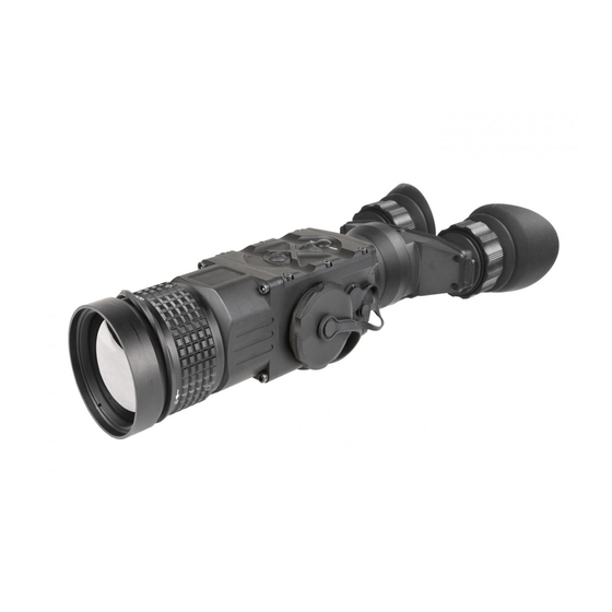
1 GENERAL INFORMATION SYSTEM DESCRIPTION The Cobra consists of next primary parts: a body, a lens assembly and an eyepiece assembly. Figure 1-1 represents two versions of the equipment: one including a 50 mm focal length objective lens, and the other with a 75 mm focal length objective lens. COBRA TB75 COBRA TB50 FIGURE 2-1. - Page 6 The Cobra is powered by two CR123A (2×3V) batteries. Figure 1-2 shows the Cobra. The ITEM NO. column of Table 2-1 indicates the number used to identify items in Figure 1-2. NOTE: Here and below, the example used is the Cobra with a 50mm lens. AGM Global Vision...
- Page 7 FIGURE 1-2. COBRA THERMAL IMAGING BI-OCULAR. SYSTEM DESCRIPTION TABLE 1-1. SYSTEM DESCRIPTION ITEM DESCRIPTION ITEM DESCRIPTION Objective Lens Cap Eyepiece Objective Lens Battery Cap Objective Focus Ring Mini USB Connector with a Cap Body Universal Connector with a Cap Button Control Panel Operation Switch Eyepiece Focus Ring Side Picatinny/Weaver Rail...
-
Page 8: Objective Lens Cap
The PART NO. column indicates the primary number used by the manufacturer, to identify an item. TABLE 1-3. OPTIONAL EQUIPMENT ITEM NO. DESCRIPTION PART NO. AGM WiFi Attachment 6305WIF1 AGM HD Recorder 6305HDR1 AGM Extended Battery Pack 6308EXB1 Professional Titanium Tripod with a Grip 6606TTR1 Hard Case for Storage/Transportation 6610HCS1 AGM Global Vision... -
Page 9: Objective Lens
1.4 KEY FEATURES • High-performance thermal imaging camera • Lightweight and robust design • Easy to operate • Manually adjustable eyepiece and objective lens • Real-time display • Digitally controlled features: • Palette • Enhancement • Settings • Display Brightness •... -
Page 10: Section 2. Operating Instructions
You can use the Picatinny adapter for the Advanced Wireless Remote (C) for mounting the remote control to Picatinny or Weaver rail. Install the adapter onto the rail (D). Insert the remote control into the adapter. AGM Global Vision... - Page 11 FIGURE 2-2. ADVANCED WIRELESS REMOTE CONTROL 2.1.3 INSTALLING ADDITIONAL EQUIPMENT Use the side Picatinny/ Weaver rail to install any additional equipment, such as the Digital Video Recorder or the Extended Battery Pack. 2.1.4 CONNECTING AN ADDITIONAL EQUIPMENT CAUTION: Turn off the Cobra before you begin connecting/disconnecting any external equipment and before removing the batteries.
- Page 12 ITEM NO. columns indicate the numbers used to identify items in the figures. NOTE: Various display symbols indicating the current operating state of the Cobra can be displayed permanently, may appear momentarily, or can be set to appear only when a certain function is activated. FIGURE 2-5. CONTROLS AGM Global Vision...
-
Page 13: Controls And Indicators
TABLE 2-1. CONTROLS AND INDICATORS ITEM CONTROL/INDICATOR FUNCTION Eyepiece Focus Ring Adjusts the eyepiece diopter. The total diopter adjustment range is covered with 2 turns of the ring. Operation Switch Activates the Cobra when turned to ON. Activates Standby mode when turned to STB. Deactivates the Cobra when turned to OFF. - Page 14 Once the MAIN MENU is displayed (Figure 2-7), use buttons (1) and (2) to navigate through items on the menu. Push button (3) to view the settings available for the item selected. MAIN MENU > EXIT PALETTE ENHANCEMENT SETTINGS FIGURE 2-7. MAIN MENU AGM Global Vision...
- Page 15 Navigate through sub-menu items by pushing buttons (1) and (2), except where otherwise indicated. After a menu item is selected, push button (3) to activate the selected function. The function will either be activated or will show <> symbols. When <> symbols are shown on the menu, the left and the right actions are required. Use button (1) to increase (>) the value, and button (2) to decrease (<) the value.
- Page 16 The adjustment range is from -20 to +100 with default value 60. Lower values will create an object image with softer edges. Higher values will make an object sharper, enhance details and will further increase the signal to noise ratio. AGM Global Vision...
- Page 17 SHARPNESS -20 SHARPNESS +100 FIGURE 2-12. SHARPNESS CORRECTION SMART SCENE - Smart Scene Optimization (SSO) – a fine-tuning computational correction that significantly improves an overall visual acuity for targets that have thermal signatures similar to a surrounding background. Higher values provide a more linear automatic gain control behavior and objects with similar, but not the same temperature can be differentiated with greater accuracy.
-
Page 18: Operating Procedures
(such as a welding arc). To prevent inadvertent exposure to these sources, never leave the equipment without the objective lens cap secured. Operating procedures are as follows: 1. Remove the Cobra from the carrying case. 2. Remove the objective lens cap. 3. Point the equipment at an object. AGM Global Vision... - Page 19 4. Activate the Cobra by turning the turn-pull switch ON. After approximately 3 sec, video of the thermal scene should appear. 5. Adjust the Cobra for your eyesight by turning the eyepiece focus rings CW up to the stop, and then CCW until the display and symbols are as clear as possible.
- Page 20 4. Disconnect the cable (if applicable). 5. Place the protective cap on the connector. 6. Remove the batteries. CAUTION: Do not store the Cobra with the batteries still installed. 7. Store the Cobra and all accessories in the carrying case. AGM Global Vision...
- Page 21 3 MAINTENANCE INSTRUCTIONS 3.1 OPERATOR TROUBLESHOOTING The purpose of troubleshooting is to identify the most frequent equipment malfunctions, probable causes, and corrective actions required. Table 3-1 lists the common malfunctions that may be found during the operation or maintenance of the Cobra. Perform the tests/ inspections and corrective actions in the order listed. This table does not list all of the malfunctions that may occur with your device, or all of the tests and corrective actions that may be necessary.
-
Page 22: Maintenance
2. Moisten the cloth with fresh water and gently wipe the external surfaces (except for optical surfaces). 3. Dry any wet surfaces (except for optical surfaces) with another clean, dry, soft cloth. 4. Using a lens brush, carefully remove all loose dirt from optical surfaces (objective lens and eyepiece). AGM Global Vision... - Page 23 5. Dampen a cotton swab with ethanol and lightly and slowly wipe optical surface. Clean the optical surface using circular movements, starting from the center and moving out towards the edge, not touching the lens holder and changing the cotton swab after each circular stroke. Repeat until the optical surface is clean.
-
Page 24: Section 4. Warranty Information
Customer. AGM Global Vision’s liability hereunder for damages, regardless of the form or action, shall not exceed the fees or other charges paid to AGM Global Vision by the customer or customer’s dealer. AGM Global Vision shall not, in any event, be liable for special,... - Page 25 4.1.3 PRODUCT REGISTRATION In order to validate the warranty on your product, the customer must complete and submit AGM Global Vision PRODUCT REGISTRATION FORM on our website (www.agmglobalvision.com/ customer-support). 4.1.4 OBTAINING WARRANTY SERVICE To obtain warranty service on your unit, the End-user (Customer) must notify the AGM Global Vision service department via email.
-
Page 26: Section 5. Specifications
• User-Controlled Manual Non-Uniformity Correction / Flat-Field Correction (UCMNUC/FFC) • Silent Shutterless NUC (SSN) ™ Analog Video Input/ PAL (768×574 pixels) / NTSC (640×480 pixels) Output Format (resolution) *Default setting (may be altered at the customer’s request). AGM Global Vision... - Page 27 TABLE 5-2. OPTICAL DATA ITEM COBRA TB50-336 COBRA TB50-640 COBRA TB75-336 COBRA TB75-640 - ang. X degrees 14.8 Field of View - ang. Y degrees 11.8 Objective Focal Length 50mm 75mm Objective F-number Exit Pupil Diameter 14mm Eye Relief 16mm Focus Method Manual Focusing Range...
-
Page 28: Appendix
The PART NO. column indicates the primary number used by the manufacturer, which controls the design and characteristics of the item in terms of its engineering drawings, specifications, standards, and inspection requirement, to identify an item. FIGURE A-1. COBRA SPARE PARTS LIST AGM Global Vision... - Page 29 TABLE A-1. COBRA SPARE PARTS LIST ITEM DESCRIPTION PART NO. 50mm Objective Lens Cap GOL50OBLCP 75mm Objective Lens Cap GOL75OBLCP 50mm Objective Lens Assembly GOL50OBLAS 75mm Objective Lens Assembly GOL75OBLAS Battery Cap AGMTIDBCP Connector Cap AGMTIDCNCP Operation Switch (not shown) AGMTIDOPSW Eyepiece Assembly AGMTIBIPAS...
- Page 30 AGM Global Vision...
- Page 31 Cobra USER MANUAL...
- Page 32 AGM Global Vision 173 West Main Street PO Box 962 Springerville, AZ 85938 Tel. 928.333.4300 Fax 480.393.4882 info@agmglobalvision.com www.agmglobalvision.com AGMglobalvision.com...
Need help?
Do you have a question about the COBRA Series and is the answer not in the manual?
Questions and answers