Table of Contents

Related Manuals for Mannesmann Rexroth DKR02

Summary of Contents for Mannesmann Rexroth DKR02
- Page 1 Rexroth DKR02, DKR03 and DKR04 Drive Controllers Project Planning Manual SYSTEM200 Rexroth Indramat DOK-DIAX03-DKR********-PR02-EN-P LSA Control S.L. www.lsa-control.com comercial@lsa-control.com (+34) 960 62 43 01...
- Page 2 About this Documentation DKR Drive Controllers DKR02, DKR03 and DKR04 Drive Controllers Title Project Planning Manual Type of Documentation DOK-DIAX03-DKR********-PR02-EN-P Document Typecode • Document Number: 120-0700-B326-02/EN Internal File Reference This document serves the purpose of: Purpose of Documentation • planning the mechanics of the control cabinet, •...
- Page 3 DKR Drive Controllers About this Documentation Supplementary documentation Note: The following documentation is not required in its entirety for the correct use of the drive controllers DKR. Title Type of Document Typecode Part Documentation Number AC Drive Units in Hazardous Areas Instructions for DOK-GENERL-ANTR*EXPLOS-ANxx-EN-P 266 304...
- Page 4 About this Documentation DKR Drive Controllers Changes from previous version Note: The following list may not be absolutely complete. The author reserves the right to make changes to this list as needed. Where? What? Supplementary documentation included General Safety Guidelines update Appropriate use added Record of Revisions added...
-
Page 5: Table Of Contents
2.12 Protection against pressurized systems ..................2-10 Introducing the devices Drive controllers ..........................3-1 General features ........................3-1 Brake resistor ..........................3-5 Technical data DKR02............................4-1 DKR03............................4-2 DKR04............................4-4 DZB01 ............................4-5 Planning the cabinet Ambient conditions......................... 5-1 Cooling method ..........................5-2 Determine energy dissipation .................... - Page 6 Contents DKR Drive Controllers Required distances for cooling with air from inside the cabinet..........5-9 DKR02............................ 5-10 DKR03............................ 5-12 DKR04............................ 5-14 DZB01 ............................ 5-16 Additional dimensions when cooling with a duct................5-17 Leads............................5-20 Measures to avoid sources of interference in the control cabinet..........5-22 Planning the electrical connections Preliminary remark .........................
- Page 7 Type code of the auxiliary bleeders ....................9-4 10 Mounting and installation 10-1 10.1 Adapting the cooling method......................10-1 DKR02 and DKR03........................ 10-1 DKR04............................ 10-3 10.2 Mounting the drive........................10-6 10.3 Drive wiring........................... 10-9 Power connector with double cable ..................10-10...
- Page 8 Contents DKR Drive Controllers Notes DOK-DIAX03-DKR********-PR02-EN-P LSA Control S.L. www.lsa-control.com comercial@lsa-control.com (+34) 960 62 43 01...
-
Page 9: Important Directions For Use
DKR Drive Controllers Important directions for use Important directions for use Appropriate use Introduction Rexroth Indramat products represent state-of-the-art developments and manufacturing. They are tested prior to delivery to ensure operating safety and reliability. The products may only be used in the manner that is defined as appropriate. -
Page 10: Areas Of Use And Application
Important directions for use DKR Drive Controllers Areas of use and application Drive controllers made by Rexroth Indramat are designed to control electrical motors and monitor their operation. Control and monitoring of the motors may require additional sensors and actors. Note: The drive controllers may only be used with the accessories and parts specified in this document. -
Page 11: Safety Instructions For Electric Servo Drives And Controls
DKR Drive Controllers Safety instructions for electric servo drives and controls Safety instructions for electric servo drives and controls Introduction Read these instructions before the equipment is used and eliminate the risk of personal injury or property damage. Follow these safety instructions at all times. -
Page 12: Hazards By Inappropriate Use
Safety instructions for electric servo drives and controls DKR Drive Controllers Hazards by inappropriate use High voltage and high discharge current! Danger to life, risk of severe electrical shock and risk of injury! DANGER Dangerous movements! Danger to life and risk of injury or equipment damage by unintentional motor movements! DANGER... -
Page 13: General Information
DKR Drive Controllers Safety instructions for electric servo drives and controls General information • Rexroth Indramat GmbH is not liable for damages resulting from failure to observe the warnings given in these documentation. • Order operating, maintenance and safety instructions in your language before starting up the machine. -
Page 14: Protection Against Contact With Electrical Parts
Safety instructions for electric servo drives and controls DKR Drive Controllers Protection against contact with electrical parts Note: This section refers to equipment with voltages above 50 Volts. Making contact with parts conducting voltages above 50 Volts could be dangerous to personnel and cause an electrical shock. When operating electrical equipment, it is unavoidable that some parts of the unit conduct dangerous voltages. - Page 15 DKR Drive Controllers Safety instructions for electric servo drives and controls To be observed with electrical drives, power supplies, and filter components: High electrical voltage! High leakage current! Danger to life, danger of injury and bodily harm from electrical shock! ⇒...
-
Page 16: Protection By Protective Low Voltage (Pelv) Against Electrical Shock
Safety instructions for electric servo drives and controls DKR Drive Controllers Protection by protective low voltage (PELV) against electrical shock All connections and terminals with voltages between 5 and 50 Volts on INDRAMAT products are protective low voltages designed in accordance with the following standards on contact safety: •... - Page 17 DKR Drive Controllers Safety instructions for electric servo drives and controls Dangerous movements! Danger to life and risk of injury or equipment damage! ⇒ Personnel protection must be secured for the above listed reason by means of superordinate monitors or DANGER measures.
-
Page 18: Protection Against Magnetic And Electromagnetic Fields During Operations And Mounting
Safety instructions for electric servo drives and controls DKR Drive Controllers ⇒ Disconnect electrical power to the equipment using a master switch and secure the switch against reconnection for: - maintenance and repair work - cleaning of equipment - long periods of discontinued equipment use ⇒... -
Page 19: Protection Against Contact With Hot Parts
DKR Drive Controllers Safety instructions for electric servo drives and controls Protection against contact with hot parts Housing surfaces could be extremely hot! Danger of injury! Danger of burns! ⇒ Do not touch surfaces near the source of heat! Danger of burns! CAUTION ⇒... -
Page 20: Battery Safety
2-10 Safety instructions for electric servo drives and controls DKR Drive Controllers 2.11 Battery safety Batteries contain reactive chemicals in a solid housing. Inappropriate handling may result in injuries or equipment damage. Risk of injury through incorrect handling! ⇒ Do not attempt to reactivate discharged batteries by heating or other methods (danger of explosion and corrosion). -
Page 21: Introducing The Devices
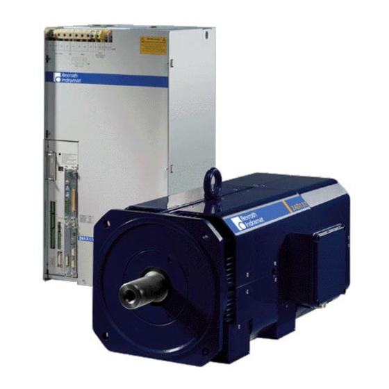
DKR Drive Controllers Introducing the devices Introducing the devices Drive controllers General features DKR3.tif Fig. 3-1: The DKR03 drive controller Drive controllers of the DKR type have been designed for digital intelligent Application range control of the following Rexroth Indramat motors: •... - Page 22 Regenerated braking energy is supplied to the mains again – also in case of emergency stop. DKR02 and DKR03 devices can be ordered with an integrated brake resistor, the DKR04 device can be expanded by an external brake resistor. This allows decelerating a drive even if the mains fails.
- Page 23 DKR Drive Controllers Introducing the devices tz /M a in to r S te rs p lta g Firmware module S l o Command S l o interface card S l o Configuration rating plate S l o S l o Firmware Rating plate, rating plate...
- Page 24 Introducing the devices DKR Drive Controllers Auxiliary plug-in modules with the following features are currently Auxiliary plug-in modules available: • modules with digital I/Os for bidirectional data exchange, • modules for different types of measuring systems: • incremental measuring systems with square-wave signal output •...
-
Page 25: Brake Resistor
Note: Devices of type DKR04.1-WxxxE are ready for operation only with brake resistor DZB01.1-W720N! As an option, devices DKR02.1 and DKR03.1 are available with integrated DKR02.1 and DKR03.1 brake resistor. DOK-DIAX03-DKR********-PR02-EN-P LSA Control S.L. www.lsa-control.com comercial@lsa-control.com (+34) 960 62 43 01... - Page 26 Introducing the devices DKR Drive Controllers Notes DOK-DIAX03-DKR********-PR02-EN-P LSA Control S.L. www.lsa-control.com comercial@lsa-control.com (+34) 960 62 43 01...
-
Page 27: Technical Data
DKR Drive Controllers Technical data Technical data DKR02 Designation Symbol Unit Designation of the drive controller DKR02.1-W200-... DKR02.1-W300-... DKR02.1-F200-... DKR02.1-F300-... 3xAC 400 ... 480, ± 10% Rated power voltage System frequency 50 ... 60 AC 230 V, ± 10% Control voltage Control voltage frequency 50 ... -
Page 28: Dkr03
Max. installation elevation without m/sea lev. 0 ... 1000 nominal data derating Protection category IP 20 per EN60529 / IEC529 Tact frequency of the power section Fig. 4-1: Technical data DKR02 DKR03 Designation Symbol Unit Designation of the drive controller DKR03.1-W100-... - Page 29 DKR Drive Controllers Technical data Auxiliary brake resistor (Option) max. braking energy of the brake resistor Continuous power of the brake resistor Peak power of the brake resistor Cooling method build-in blower Weight Drive controller approx. 49 Accessories kit M1-RAC 3 Ambient conditions Perm.
-
Page 30: Dkr04
Technical data DKR Drive Controllers DKR04 Designation Symbol Unit Designation of the drive controller DKR04.1-W300-... DKR04.1-W400-... DKR04.1-F300-... DKR04.1-F400-... 3xAC 400 ... 480, ± 10% Rated power voltage System frequency 50 ... 60 AC 230 V, ± 10% Control voltage 50 ... 60, ± 2 Hz Control voltage frequency Control voltage power Continuous current of the drive... -
Page 31: Dzb01
DKR Drive Controllers Technical data DZB01 Designation Symbol Unit Designation of the auxiliary brake resistor DZB01.1-W720N Ω Resistor Continuous power Cont Peak power max. braking energy Cooling method build-in blower DC 24 V, ± 20% Voltage of the blower Lü Current of the blower 0,22 Lü... - Page 32 Technical data DKR Drive Controllers Notes DOK-DIAX03-DKR********-PR02-EN-P LSA Control S.L. www.lsa-control.com comercial@lsa-control.com (+34) 960 62 43 01...
-
Page 33: Planning The Cabinet
DKR Drive Controllers Planning the cabinet Planning the cabinet Ambient conditions The nominal data (see chapter 4) are valid for Ambient temperature and installation elevation • ambient temperatures from +5° to +45° C and • installation elevation from 0 to 1000 m above sea level. Note: In case you want to use the drive controller under other ambient conditions than the indicated ones (up to a maximum... -
Page 34: Cooling Method
Planning the cabinet DKR Drive Controllers Case 1: The ambient temperature exceeds the nominal data - or - the installation elevation exceeds the nominal data: 1. Determine the load capacity by means of the above figure. 2. Multiply the nominal data indicated in the Technical Data by the determined load capacity. - Page 35 DKR 02/03 DKR 04 heatsink heatsink external power press. air flow Q loss P V(ext) DKR04 Symbol Unit DKR02 DKR03 max pressure min. air flow 76,1 db(A) 50 Hz noise db(A) 75,5 60 Hz KRDKR Fig. 5-2: Energy dissipated, air flow data and noise emissions The energy dissipated both internally and externally is load-dependent.
-
Page 36: Possible Cooling Method Variants
Planning the cabinet DKR Drive Controllers Possible cooling method variants The design of the devices offers several possibilities to cool the drive controller: • with air from inside the cabinet • with air from outside the cabinet • duct cooling Note: The details on how to adapt the various cooling methods are outlined in section 10.1. - Page 37 DKR Drive Controllers Planning the cabinet Cooling with air from Cooling with air from outside of control enclosure intside of control enclosure air outlet air outlet control control enclosure rear enclosure rear wall or wall or mounting mounting panel panel with vents without vents air inlet...
- Page 38 Planning the cabinet DKR Drive Controllers Cooling with air duct air outlet N L K 220 V Steuerspannun Netz/Mains Motor Aux. Voltage DIAX03 DKR03 air inlet SchDKR Fig. 5-5: Cooling method via duct (the example shown is a DKR03) Cooling with air from outside the cabinet or with a duct affects the protection category of the cabinet because such methods mean that there must be vents in the cabinet.
-
Page 39: Use Of Cooling Units
DKR Drive Controllers Planning the cabinet Use of cooling units The drive may be operated without reduction of drive data up to an ambient temperature of 45°C. Exceeding this may mean that it might be necessary to use a heat exchanger. When using heat exchangers condensed water is produced due to the Avoiding water that drips or is sprayed... - Page 40 Planning the cabinet DKR Drive Controllers correct incorrect Cabinet Cabinet Air inlet Air inlet Air outlet duct Cooling Cooling system system electronic electronic equipment equipment Eb0002f1.fh7 Fig. 5-7: Arranging the heat exchanger on the front of the control cabinet Avoiding moisture condensate When using heat exchangers the drive controller might be damaged by moisture condensate!
-
Page 41: Dimension Sheets
DKR Drive Controllers Planning the cabinet Dimension sheets Damage to devices caused by wrong mounting position! ⇒ In order to avoid damage to the devices caused by wrong mounting position, only install the devices in CAUTION accordance with the indicated mounting positions. Required distances for cooling with air from inside the cabinet min. -
Page 42: Dkr02
220 V Netz/Mains Motor Steuer- air outlet spannung Aux. Voltage (option) air inlet (option) DIAX03 DKR02 air inlet (as delivered) all dimensions in mm MBDKR2 Fig. 5-9: Unit dimensions DKR02 DOK-DIAX03-DKR********-PR02-EN-P LSA Control S.L. www.lsa-control.com comercial@lsa-control.com (+34) 960 62 43 01... - Page 43 5-11 DKR Drive Controllers Planning the cabinet Distances, drill diagram and vents Note: The vents in the back wall of the cabinet or mounting panel are only required if the drive is cooled with air from outside the unit. control enclosure rear wall or mounting panel min.
-
Page 44: Dkr03
5-12 Planning the cabinet DKR Drive Controllers DKR03 Unit dimensions air outlet (as delivered) 190 ± 0,5 max. N L K 220 V Steuerspannun Netz/Mains Motor Aux. Voltage air outlet (option) DIAX03 DKR 03 air inlet (option) 210 ± 0,5 air inlet all dimensions in mm (as delivered) - Page 45 5-13 DKR Drive Controllers Planning the cabinet Distances, drill diagram and vents Note: The vents in the back wall of the cabinet or mounting panel are only required if the drive is cooled with air from outside the unit. Control enclosure rear wall or mounting panel min.
-
Page 46: Dkr04
5-14 Planning the cabinet DKR Drive Controllers DKR04 Note: If the cooling method implementing outside air is used, and the rear wall or mounting panel are "thin", then it is recommended to mount with frame M1-RAC4. This additional frame helps to stabilize the mounting surface. - Page 47 5-15 DKR Drive Controllers Planning the cabinet Distances, drill diagram and vents Note: The vents in the back wall of the cabinet or mounting panel are only required if the drive is cooled with air from outside the unit. control enclosure rear wall or mounting panel 460 ±0,5 (20)
-
Page 48: Dzb01
5-16 Planning the cabinet DKR Drive Controllers DZB01 Unit dimensions Fig. 5-15: Unit dimensions DZB01 DOK-DIAX03-DKR********-PR02-EN-P LSA Control S.L. www.lsa-control.com comercial@lsa-control.com (+34) 960 62 43 01... -
Page 49: Additional Dimensions When Cooling With A Duct
Ø 125 part no.: 238354 flange 2 • all dimensions in mm • ducts must be ordered separately zMSchDKR Fig. 5-16: Additional dimensions when cooling with a duct - DKR02/DKR03 DOK-DIAX03-DKR********-PR02-EN-P LSA Control S.L. www.lsa-control.com comercial@lsa-control.com (+34) 960 62 43 01... - Page 50 5-18 Planning the cabinet DKR Drive Controllers closed mounting panel air inlet bend mounting (without vents) radius clearance with vertikal min. air inlet R=125 min.260 flange 2 min. DIAX03 DKR 04 flange I duct Ø 125 mounting part no.: 238354 clearance with (is not a part of horizontal air inlet...
- Page 51 5-19 DKR Drive Controllers Planning the cabinet 15° 60 +2 MBFL1DKR all dimensions in mm Fig. 5-18: Flange 2 ±0,1 ±0,3 (7,9) 100 ±0,5 91 +0,5 all dimensions in mm MBFL2DKR Fig. 5-19: Flange DOK-DIAX03-DKR********-PR02-EN-P LSA Control S.L. www.lsa-control.com comercial@lsa-control.com (+34) 960 62 43 01...
-
Page 52: Leads
5-20 Planning the cabinet DKR Drive Controllers Leads Failure or malfunction caused by improperly installed leads! ⇒ Observe the following instructions. CAUTION ⇒ Maintain a distance of at least 100 mm between power and control or Lead arrangement signal cables, e. g.; feedback or NC connections - or - ⇒... - Page 53 5-21 DKR Drive Controllers Planning the cabinet • Maximum length of the motor cable is 75 meters Length of the leads • Maximum length of the feedback connection is 75 meters Failure or malfunction caused by clamping points or intermediate coupler units! ⇒...
-
Page 54: Measures To Avoid Sources Of Interference In The Control Cabinet
5-22 Planning the cabinet DKR Drive Controllers Measures to avoid sources of interference in the control cabinet Failure and malfunction caused by interference signals! ⇒ Observe the following instructions, in order to avoid electromagnetic or lead-related interference signals. CAUTION If inductive loads, e.g., chokes, contactors or relays, must be switched with the use of a contact or semi-conductor, then these must be shielded: ⇒... -
Page 55: Planning The Electrical Connections
DKR Drive Controllers Planning the electrical connections Planning the electrical connections Preliminary remark Note: interconnecting diagrams made available Rexroth Indramat exclusively serve to prepare the circuit diagrams of the plant! When wiring the plant, always use the circuit diagrams made available by the manufacturer of the machine! Fundamental guidelines Damage to persons or property caused by... -
Page 56: Positions Of The Connectors, Pin Configurations And Lead Cross Sections
Bb1, UD, TVW, K1NO, K1NC (X7) analog measuring outputs motor feedback AnDKR AK1, AK2, (X3) connection (X4) Fig. 6-1: Front of unit DKR02/DKR03 with connections labeled, names and explanations Note: Except for terminal connectors X5, X6 and X10 the arrangement connections DKR04 devices corresponds to the arrangement on DKR02/DKR03 devices. - Page 57 DKR Drive Controllers Planning the electrical connections RS 232 interface connecting the optional plug-in mudules as per the relvant diagrams analoge 0 VM diagnostics outputs 0 VM ready for power start inhibit +15 VM encoder interface: load with connection of the DSF 0 VM 50 mA encoder (digital servo...
-
Page 58: Mains Connection
Planning the electrical connections DKR Drive Controllers terminal connector designation lead cross sections 10...35 finely stranded cable assembly made by Rexroth Indramat Fig. 6-3: Lead cross sections [mm²] Mains connection Failure or malfunction caused by a FI current limiting type circuit breaker! ⇒... -
Page 59: Ungrounded Three-Phase System
DKR Drive Controllers Planning the electrical connections TT mains power circuit breaker 230 V ±10 % 50...60 Hz autotransformer drops drops off with off if voltage does not AC 230 V need to be matched! AP1DKR power circuit breaker: For primary protection of transformers with a high degree inrush peak... - Page 60 Planning the electrical connections DKR Drive Controllers IT mains power circuit breaker control enclosure grounding potential 230V ±10% 50...60Hz drops off with AC 230 V AP2DKR power circuit breaker: For primary protection of transformers with a high degree inrush peak (e.
- Page 61 DKR Drive Controllers Planning the electrical connections The following two figures show you • the connection to ungrounded three-phase systems with overvoltage suppressor and • two possibilities for triggering the separation of the drive from the network with this setup. main switch drops off if voltage of machine...
- Page 62 Planning the electrical connections DKR Drive Controllers drops off if voltage does not need to be IT mains matched! power circuit breaker 230 V ±10% 50...60 Hz drops off with AC 230 V control enclosure grounding potential bridge removed AP4DKR power circuit breaker: For primary protection of transformers with a high degree...
-
Page 63: Dimensioning
Minimum mains fuse F1, type Minimum lead cross controller section in mm² DKR03.1-100-... 3 x NH25gl DKR03.1-200-... 3 x NH35gl DKR02.1-200-... 3 x NH50gl DKR02.1-300-... 3 x NH63gl DKR04.1-300-... 3 x NH80gl DKR04.1-400-... 3 x NH80gl Fig. 6-8: Minimum data for mains fuses and lead cross sections Calculate the lead cross sections required in terms of the actual motor power and the highest ambient temperatures. - Page 64 6-10 Planning the electrical connections DKR Drive Controllers The nominal current required is not dependent on the mains voltage. There is a thyristor bridge on the mains of the DKR which operates with phase control at a mains voltage of > 400 V. This keeps the DC bus voltage at approximately 520 V.
-
Page 65: Autotransformers
6-11 DKR Drive Controllers Planning the electrical connections Autotransformers Damage to the autotransformer if it is not sized large enough! ⇒ Please note the following guidelines. CAUTION ⇒ Dimension the power S of a possibly required autotransformer in Netz terms of the rated motor power or at least, however, in terms of the actual continuous motor power: NetzDKR DauerMotor... -
Page 66: Isolating Transformers
Type of drive controller Minimum power of the isolating transformer (S ) [kVA] Netz DKR03.1-100-... DKR03.1-200-... DKR02.1-200-... DKR02.1-300-... DKR04.1-300-... DKR04.1-400-... Fig. 6-13: Minimum power of the isolating transformer depending on the drive controller in use ⇒ Make sure that the inductive components of the relative short-circuit voltage u are less than 4 % (calculation: see Fig. -
Page 67: Overvoltage Suppressor
Type of drive controller Fuse F3, Type Overvoltage suppressor F2, Type DKR03.1-100-... ® e. g. DEHNguard manufactured by DKR03.1-200-... DEHN + SÖHNE DKR02.1-200-... D-92306 Neumarkt Tel: +49 (0)9181/906-0 DKR02.1-300-... DKR04.1-300-... 100Agl DKR04.1-400-... Fig. 6-14: Types of fuses and overvoltage suppressors DOK-DIAX03-DKR********-PR02-EN-P LSA Control S.L. -
Page 68: Functions And Allocations Of Individual Interfaces
6-14 Planning the electrical connections DKR Drive Controllers Functions and allocations of individual interfaces X2: Serial interface The serial interface serves for the communication between the drive controller and a PC. It is needed for programming, parameterization and diagnosis during commissioning and service. For this purpose the appropriate software (e. - Page 69 6-15 DKR Drive Controllers Planning the electrical connections RS-485 interface The RS-485 interface enables: • the implementation of a serial bus with up to 31 participants connected via a two-wire line (half duplex mode), i. e., it can be used to start up several DKCs with DriveTop without having to plug into a different socket of the interface cable, •...
-
Page 70: X3: Analog Output And Signal Contact
6-16 Planning the electrical connections DKR Drive Controllers X3: Analog output and signal contact Inside the unit Connection outside the unit Diagnostic output/ channel1; output voltage: DC ±10 V current capacity: 4 mA Diagnostic output/ channel2; output voltage: DC ±10 V current capacity: 4 mA Ground Bb contact 1) -
Page 71: X4: Motor Feedback
6-17 DKR Drive Controllers Planning the electrical connections By means of the inputs AS+ and AS- you can avoid unintended starting of Starting lockout the motor in case of failure. (inputs AS+, AS-) Note: With this function it is impossible to stop axes which are moving! The function "starting lockout"... -
Page 72: X6: Monitoring Motor Temperature And Holding Brakes
6-18 Planning the electrical connections DKR Drive Controllers X6: Monitoring motor temperature and holding brakes temperature motor holding monitoring brake max. core cross section: 2,5 APX6DKR Fig. 6-18: Connector assignment at X6 Both motor temperature and holding brake are monitored and controlled by the drive controller. -
Page 73: X7: Signal Outputs
6-19 DKR Drive Controllers Planning the electrical connections Possible malfunction caused by inappropriate holding brake! ⇒ Maximum permissible braking current: 2 A. Note that the maximum braking current can effect the voltage CAUTION output "DC +24 V" at X8 (see page 6-20). ⇒... -
Page 74: X8: Signal Voltages
6-20 Planning the electrical connections DKR Drive Controllers The TVW contact opens with an overload of the internal optional Temperature pre-warning emergency brake resistor [or the external brake resistor (only DKR4.1)]. (TVW contact) The K1NC contact is closed if the internal mains contactor has dropped Acknowledge power OFF (K1NC contact) off. -
Page 75: X9: Control Inputs For Internal Power Contactors
6-21 DKR Drive Controllers Planning the electrical connections X9: Control inputs for internal power contactors open external closed external inside outside the unit the unit contact effects: contact effects: inhibit to regenerate energy power off ready for power off power on External contact requirements: DC 24 V/625 mA Maximum core cross section: 2,5 mm SBX9DKR... - Page 76 6-22 Planning the electrical connections DKR Drive Controllers Brake resistor connection X10/R1 and X10/R2 Note: Only DKR04.1 devices have terminal connectors for the brake resistor connection (DZB01.1). DZB01.1 is the brake resistor for DKR04.1. The electronic system required to run the DZB01.1 has only been integrated in the “E version”...
-
Page 77: Accessories
DKR Drive Controllers Accessories Accessories Connector kits The following is required to connect the drive: • connector kit S1-DKS 1 (for the connections on the basic unit without feedback connector) and • connector kit S..-DDS 2 (for the connections of all the plug-in modules inserted in the basic unit including the feedback connector). -
Page 78: Connector Kit For All Plug-In Modules Of A Configuration Including The Feedback Connections
Accessories DKR Drive Controllers Connector kit for all plug-in modules of a configuration including the feedback connections Which S..-DDS 2 connector set is required depends on the configuration of the drive. In addition to the connectors for all the plug-in modules, the feedback to drive connector is also included herein. -
Page 79: Fiber Optic Cables
DKR Drive Controllers Accessories Fiber optic cables Drives equipped with SERCOS interface are connected to higher-ranking control units with the use of fiber optic cables. It is necessary, however, to order these fiber optic cables (cable, connector or a cable assembly) separately. Length in meters IKO 985 / . -
Page 80: Mechanical Accessories
Accessories for duct cooling The accessories required with duct cooling depend upon the drive. The accessories needed for DKR02 and DKR03 drives are contained in the accessory kit "M1-RAC3". The conversion accessories for the DKR04 drive are in the accessory kit "M2-RAC2". -
Page 81: Transport And Storage
DKR Drive Controllers Transport and storage Transport and storage Transport Damage to property caused by inappropriate transport! ⇒ Use a suitable mode of transportation. ⇒ Use shock-damped supports if excessive shocks CAUTION could occur during transport. ⇒ Transport those components that could be damaged by any electrostatic loads, plug-in modules for example, in packaging that is capable of conducting such loads. - Page 82 Transport and storage DKR Drive Controllers Notes DOK-DIAX03-DKR********-PR02-EN-P LSA Control S.L. www.lsa-control.com comercial@lsa-control.com (+34) 960 62 43 01...
-
Page 83: Identifying The Merchandise
DKR Drive Controllers Identifying the merchandise Identifying the merchandise General The drive is packaged in a carton with all its accessories at the time of delivery. An envelope is attached to this carton. This envelope contains one copy of the delivery slip. If additional delivery documents are needed, then these must be requested. -
Page 84: Rating Plate And Type Code Of The Drive Controller
PosTSDKR firmware basic unit Fig. 9-2: Positions of the rating plates (DKR02/DKR03) Note: Compare all the information on the rating plate with what is actually assembled into the drive. DOK-DIAX03-DKR********-PR02-EN-P LSA Control S.L. www.lsa-control.com comercial@lsa-control.com (+34) 960 62 43 01... - Page 85 DKR Drive Controllers Identifying the merchandise SYSTEMCONFIGURATION type of the configured DKR03.1-W100N-BE23-00-FW drive controller type of the basic unit DKR03.1-W100-B DSS 2.1M DEA 4.1M type of the plug- slot COVER in module designation COVER type of the DSM 2.3-FW software module type of the configuration TYS-DKR03.1-W100N-BE32-00...
-
Page 86: Type Code Of The Auxiliary Bleeders
Identifying the merchandise DKR Drive Controllers Type code of the auxiliary bleeders Example: D Z B 1 . 1 - W 7 2 Product groupe Line Version Cooling mode air, internal (by build-in blower).….W Brake energy 720 kWs.............720 Nominal voltage, blower DC 24 V..........…..N TLDZB.fh7 Fig. -
Page 87: Mounting And Installation
10.1 Adapting the cooling method DKR02 and DKR03 Drive controllers of type DKR02 and DKR03 are supplied for "Cooling with air from inside the cabinet". If a different cooling method is required, then the drive must be converted before it is mounted into the cabinet. - Page 88 1 LUFTDKR3.FH7 as delivered conversion as mounted (side view) (perspective) (side view) Fig. 10-1: Converting the cooling method to use outside air (DKR02/DKR03) DOK-DIAX03-DKR********-PR02-EN-P LSA Control S.L. www.lsa-control.com comercial@lsa-control.com (+34) 960 62 43 01...
-
Page 89: Dkr04
1 (flange) USchDKR Fig. 10-2: Converting to cooling with duct (DKR02/DKR03) DKR04 Drive controllers of type DKR04 are supplied for "Cooling with air from outside the cabinet". If a different cooling method is required, then the drive must be converted before it is mounted into the cabinet. - Page 90 10-4 Mounting and installation DKR Drive Controllers Conversion to cooling method using air inside of cabinet It is necessary to convert the cooling method, if Conversion criteria • there are no rectangular vents near the controller heatsink in the mounting panel of the control cabinet •...
- Page 91 10-5 DKR Drive Controllers Mounting and installation Conversion to cooling with duct Note: If you want to make use of the possibility “Cooling with duct”, there mustn’t be any vents near the controller heatsink in the mounting panel of the control cabinet. For the conversion to “Cooling with duct”...
-
Page 92: Mounting The Drive
10-6 Mounting and installation DKR Drive Controllers 10.2 Mounting the drive Lethal electric shock caused by live parts with more than 50 V! ⇒ Switch power off to the control cabinet before beginning work. Make sure that the power supply DANGER switch cannot be unintentionally or inadvertently switched back on. - Page 93 M ot St eu er sp X 10 A ux lta ge GEDKR3 Fig. 10-5: An example for mounting the DKR02/DKR03 (Cooling method: with air from inside the cabinet) DOK-DIAX03-DKR********-PR02-EN-P LSA Control S.L. www.lsa-control.com comercial@lsa-control.com (+34) 960 62 43 01...
- Page 94 10-8 Mounting and installation DKR Drive Controllers MontDKR Fig. 10-6: Mounting the DKR04 with mounting frame (Cooling method: with air from outside the control cabinet) DOK-DIAX03-DKR********-PR02-EN-P LSA Control S.L. www.lsa-control.com comercial@lsa-control.com (+34) 960 62 43 01...
-
Page 95: Drive Wiring
10-9 DKR Drive Controllers Mounting and installation 10.3 Drive wiring Note: All of Rexroth Indramat’s terminal connecting diagrams exclusively serve the purpose of generating the circuit diagrams of the machine! The circuit diagrams of the machinery supplied by the manufacturer are to be used when wiring the plant! Lethal electric shock caused by live parts with more than 50 V! -
Page 96: Power Connector With Double Cable
10-10 Mounting and installation DKR Drive Controllers Damage to electronic components caused by electrostatic discharge! ⇒ Before working on electronic components and equipment, touch a grounded object as, for example, CAUTION the doors of the cabinet. This discharges the human body. -
Page 97: Service And Checks
11-1 DKR Drive Controllers Service and checks Service and checks 11.1 Error diagnoses The drive signals drive problems via • the SERCOS interface and • the H1 display on the front of the unit. In order to be able to interpret error messages of the drive controller, you Diagnosis by means of need the documentation with the (sub)title "Troubleshooting Guide". -
Page 98: Repairing And Replacing Units
⇒ Loosen the fixing screws on top and bottom of the device (do not unscrew!). Lift the device off the fixing screws with appropriate hoisting gear (DKR02: approx. 120 kg, DKR03: approx. 49 kg, DKR04: approx. 150 kg) and take it out. - Page 99 DKR02 and DKR03: Verify the conversion criteria by means of the instructions in chapter “Adapting the cooling method“ from page 10-1. DKR04: Verify the conversion criteria by means of the instructions in chapter “Adapting the cooling method“...
-
Page 100: Fault Report
11-4 Service and checks DKR Drive Controllers 11.3 Fault report Fault Report for digital DKR AC Drives This fault report supports clarification of problems and their causes. It is absolutely necessary for finding and eliminating even hidden, sporadic or application-specific problems. - Always include a fault report when sending us a unit. -
Page 101: Index
TVW contact brake resistor 3-5, 6-22 ambient conditions 4-5 technical data 4-5 type code 9-4 unit dimensions 5-16 brake resistor in DKR02 technical data 4-1 brake resistor in DKR03 technical data 4-3 command interface card 3-3 configuration 9-3... - Page 102 12-2 Index DKR Drive Controllers distances, drill diagram and vents 5-11 technical data 4-1 unit dimensions 5-10 DKR03 ambient conditions 4-3 distances, drill diagram and vents 5-13 technical data 4-2 unit dimensions 5-12 DKR04 ambient conditions 4-4 distances, drill diagram and vents 5-15 technical data 4-4 unit dimensions 5-14 drive...
- Page 103 12-3 DKR Drive Controllers Index mains fuse 6-9 motor connection 10-9 see power connection motor feedback 6-17 motor holding brake 6-18 motor power cables 6-1 motor temperature monitoring 6-18 NFD see mains filter noise emissions 5-3 OFF contact see control power contactor ON contact see control power contactor overvoltage 6-4 overvoltage suppressor 6-6, 6-13...
- Page 104 12-4 Index DKR Drive Controllers DOK-DIAX03-DKR********-PR02-EN-P LSA Control S.L. www.lsa-control.com comercial@lsa-control.com (+34) 960 62 43 01...
-
Page 105: Service & Support
13-1 DKR Drive Controllers Service & Support Service & Support 13.1 Helpdesk Unser Kundendienst-Helpdesk im Hauptwerk Lohr Our service helpdesk in the head factory Lohr am am Main steht Ihnen mit Rat und Tat zur Seite. Main is assisting you in all kind of queries. Sie erreichen uns You may contact us +49 (0) 9352 40 50 60... -
Page 106: Kundenbetreuungsstellen - Sales & Service Facilities
Gebiet Südwest Vertriebsgebiet Ost Vertriebsgebiet Nord Germany South Germany South-West Germany East Germany North Rexroth Indramat GmbH Mannesmann Rexroth AG Rexroth Indramat GmbH Mannesmann Rexroth AG Ridlerstraße 75 Vertrieb Deutschland – VD-BI Beckerstraße 31 Vertriebsniederlassung Region Nord 80339 München Geschäftsbereich Rexroth Indramat 09120 Chemnitz Gesch.ber. - Page 107 - service: +34 9 43 31 84 60 satindramat-goimendi@adegi.es Sweden Slowenia Switzerland -East- Switzerland -West- Rexroth Mecman Svenska AB Rexroth Indramat Mannesmann Rexroth Schweiz AG Mannesmann Rexroth Suisse SA Rexroth Indramat Division elektromotorji d.o.o. Gesch.ber. Rexroth Indramat Département Rexroth Indramat Varuvägen 7 Otoki 21 Gewerbestraße 3...
- Page 108 Australia Australia China China Shanghai Mannesmann Rexroth AIMS - Australian Industrial Mannesmann Rexroth Pty. Ltd. Mannesmann Rexroth (China) Ldt. Hydraulics & Automation Ltd. Machinery Services Pty. Ltd. No. 7, Endeavour Way 15/F China World Trade Center Wai Gaoqiao Free Trade Zone...
- Page 109 +55 (0)47 974 66 45 +55 (0)11 4075 90 70 prochnow@zaz.com.br Telefax: +55 (0)11 4075 35 52 awittwer@rexroth.com.br Mexico Mannesmann Rexroth Mexico S.A. de C.V. Calle Neptuno 72 Unidad Ind. Vallejo MEX - 07700 Mexico, D.F. Telefon: +52 5 754 17 11...
- Page 110 13-6 Service & Support DKR Drive Controllers Notes DOK-DIAX03-DKR********-PR02-EN-P LSA Control S.L. www.lsa-control.com comercial@lsa-control.com (+34) 960 62 43 01...
- Page 111 LSA Control S.L. www.lsa-control.com comercial@lsa-control.com (+34) 960 62 43 01...
- Page 112 2 6 6 6 2 6 LSA Control S.L. www.lsa-control.com comercial@lsa-control.com (+34) 960 62 43 01...
Need help?
Do you have a question about the DKR02 and is the answer not in the manual?
Questions and answers