
Subscribe to Our Youtube Channel
Summary of Contents for De Agostini Model Space Idbox pack 10
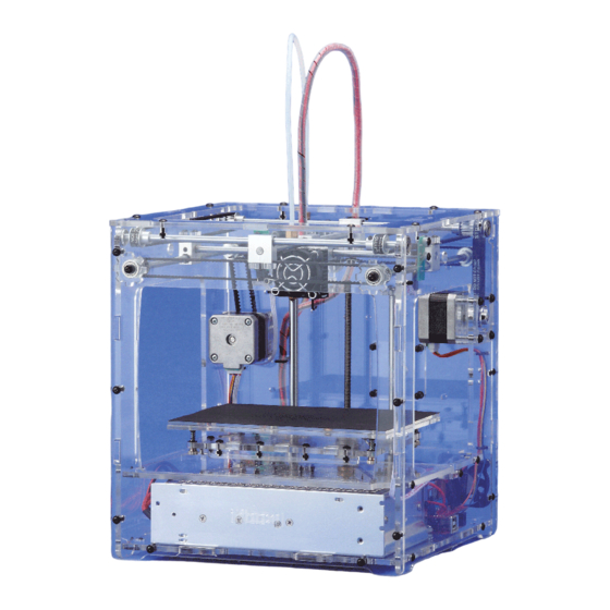
- Page 1 Pack 10 BUILD YOUR OWN Anything you can imagine, you can make! PRINTER Compatible with Windows 7 & 8 Mac OS X 3D technology is now available for you at home!
- Page 2 You will Battersea, London SW8 3HE also see how to set up the software so you can print out your 3D files successfully. Plus, how to connect the printer to your computer. Published in the USA by De Agostini Publishing USA, Inc., 121 E. Calhoun Street, Woodstock, IL 60098 Assembly Guide 263-279 The next five detailed and easy-to-follow stages of construction for your 3D printer.
-
Page 3: Computer Compatibility
User Guide User Guide Section 1: Download, install and configure Repetier-Host for the idbox In this section, you will download Repetier-Host – the software that your computer uses Computer compatibility Please check the to communicate with the idbox. You will then set up Repetier and its bundled ‘slicing’ specification of the PC you software to work with your idbox. want to connect to the idbox to see if it is suitable. - Page 4 User Guide Download and install on a Windows PC 1. On the ‘Download now’ When it has downloaded, In the ‘Select Setup This takes you to the page, click on the link for the click Run at the bottom of the Language’ dialog that Repetier-Host Setup Wizard. latest version of Repetier-Host page.
-
Page 5: Connecting The Power Cable
User Guide From this point on, the User Guide instructions assume that you have finished construction of the idbox. Do not proceed if you have not finished the idbox. Connecting the idbox to your computer and connecting the power cable Before you configure Repetier-Host to work with your idbox, you have to connect the idbox to your computer using the USB cable. Before you plug in the mains cable to the idbox, there are a couple of things that have to be done, so do not plug in until you have done these. - Page 6 User Guide Configuring Repetier-Host to work with the idbox Before you can use Repetier-Host to control the output from your idbox, you have to configure the program so it knows how to communicate with the idbox. It needs to know the idbox’s bed size, the range of the movements its printer head can do and the temperature settings for the nozzle. These settings only need to be entered once. The way to set up Repetier to work with your computer is shown below, first for a Windows computer and then for a Mac. After this, you check that the computer and idbox are connected properly. Configure Repetier-Host for a Windows computer SETTINGS Click the Printer Settings button Connector: Serial Connection...
- Page 7 User Guide 4. Click on the ‘Printer Shape’ tab to SETTINGS X Min: 0 X Max: 150 Bed Left: 0 enter information about the volume of the space the idbox can print in. Where Y Min: 0 Y Max: 130 Bed Front: 0 settings are not shown on the right, the Print Area Width: 150 mm Print Area Depth: 130 mm default values can be used.
-
Page 8: Set The Printable Area
User Guide SETTINGS SET THE PRINTABLE AREA Home X: x min Now click on the Dimension tab to enter information about the volume of the Home Y: y min space the idbox can print in. Use the Home Z: z max X Min: 0 [mm] X Max: 150 [mm] values as shown in the image on the left Y Min: 0 [mm] Y Max: 130 [mm]... - Page 9 User Guide Setting up the slicing software for the idbox To convert 3D data into the commands that control a 3D printer (G-code), you use a program called a slicer. Repetier-Host has different slicers included with it. We will use CuraEngine for Windows and Slic3r for Mac computers. Setting up the CuraEngine slicer for Windows computers 1. Open 2. On the left of the screen, Repetier, select the Print, then Speed and click on and Quality tabs.
- Page 10 Assembly Guide User Guide Click on Speed in the panel on the Infill: 60 mm/s left and enter the values as shown Solid infill: 60 mm/s or % Top solid infill: 50 mm/s or % in the image on the left and under Support material: 60 mm/s SETTINGS below.
-
Page 11: Assembly Guide
Assembly Guide Stage 41 Assembly Area Stage 41: Add the Z-axis and feeder motor drivers, and the feeder motor cable In this stage, you add the Z-axis motor driver to the driver board, then add the feeder motor driver before plugging the feeder motor cable into the driver board. The two motor drivers you add to the seated and that they are plugged in driver board this time are identical to... - Page 12 Assembly Guide Plug the motor drivers into the driver board CAUTION! Make sure that the circular element on the top of the motor Circular element driver is on the left when viewed with the front of the housing facing you. Be careful not to touch this element.
- Page 13 Assembly Guide At the other three cable tie positions Pass the feeder motor cable through Turn the housing so the front is facing you. (outlined in red, above), use the cable ties the hole in the casing to the left of the Untwist the feeder motor cable you’ve just to secure the feeder motor cable and the noise filter.
- Page 14 Assembly Guide Stage 42 Assembly Area Stage 42: Connect up the power supply and fix it to the housing In this stage, you will wire up the power supply, then attach it to the housing. After that, connect up more of the wiring inside the housing. It is vital to get the wires connected properly, so take care as you do it.
- Page 15 Assembly Guide Connect up the nine screw terminals on the power supply Gap when screw is loosened 9 screw terminals There are nine screw terminals on the end of the power supply. Use a size 2 Phillips screwdriver to loosen them all before you start attaching cables. When you insert the Y-shaped end of a cable into a screw terminal, do it so...
- Page 16 Assembly Guide Right Left Turn the housing so its left side is facing you. Place the power supply as shown, so it is Pass the second thick pink cable from the to the right of the housing. Pass the rightmost of the two thick pink power cables from driver board through the hole in the front the driver board through the opening in the front panel of the housing and plug it into the panel and plug it into the power supply’s...
- Page 17 Assembly Guide Hold the power supply in position with one hand so that the four screw holes in its Tighten all four of the screws with a size 1 underside align with the screw holes in the bottom panel (ringed in red). Insert an 8mm Phillips screwdriver.
- Page 18 Assembly Guide The fan power connectors are designed to be put together so the ribs on one side of the smaller connectors fit into the slots on the larger connectors. Slots Ribs Correct Take the connector for one branch of the fan power supply wires, and plug it into the connector for the fan at Incorrect the lower back right of the housing.
- Page 19 Assembly Guide Stage 43 Assembly Area Stage 43: Connect the X-, Y- and Z-axis limit switches to the driver board In this stage, you connect up the three limit switches to the driver board using the two cables supplied with this stage and the one supplied with Stage 3. You will also plug in the thermistor cable to the driver board and tidy up the cables.
- Page 20 Assembly Guide Connect the cables to the limit switches The sides of the X-axis limit Y-axis limit switch connectors are switch different. Make sure you plug them in so the metal parts show. Z-axis limit Metal shows switch base on this side Plug in Connector's metal parts...
- Page 21 Assembly Guide Metal parts facing left X-axis (1st column on the right) Untwist the cable from the X-axis limit switch, if necessary, and plug the connector into the first column of pins on the right. The side of the connector where the metal parts are visible should be facing to the left. Metal parts face left Y-axis (3rd column from right) Untwist the cable from the Y-axis limit switch if necessary, and plug the connector into the third column...
- Page 22 Assembly Guide Secure the limit switch cables to the housing Rear Turn the housing so its rear panel is facing you. Pass cable ties through the two sets of holes (outlined in red) and do up the ties to secure the cables for the X-axis limit switch, as shown above. Trim the excess from the cable ties with scissors. Put the X-axis limit switch cable together Add the Z-axis limit switch cable to the Trim off the excess from the straps of the...
- Page 23 Assembly Guide Connect the thermistor cable to the driver board Thermistor cable Thermistor T0 Pins connector The thermistor, which is in the head block, The pins on the driver board for the has a cable that needs to be connected thermistor are the two on the right (with T0 Plug in connector to the driver board. Locate the thermistor...
- Page 24 Assembly Guide Stage 44 Assembly Area Stage 44: Attach two brackets to the housing and add a linear bush to the modelling table In this stage, you will attach two brackets to the housing, then add a linear bush to the table base using cap bolts (bolts with hexagonal sockets in their heads).
- Page 25 Assembly Guide Attach the brackets to the left and right surfaces of the housing Insert Insert the tab of one of the brackets into Screw the 14mm truss head screw (with Repeat the process for the other bracket the slot (outlined in red) in the left of the washer) into the nut as shown, and tighten on the right of the housing.
- Page 26 Assembly Guide Stage 45 Assembly Area Stage 45: Add a second linear bush to the table This assembly is much the same as part of that in the previous stage (Stage 44), where you added a linear bush to the table base, fastening it in place with four cap head bolts. Remember to make sure the bush is the right way up in its hole in the table.
- Page 27 Assembly Guide Attach the linear bush to the table base Hole for linear bush Screw holes With the dog at the top left, locate the circular Put the shaft of the bush through Hold the bolts in position and turn the hole surrounded by four screw holes at the top the hole and put a 15mm M3 cap table over. Put an M3 flat washer and...
- Page 28 User Guide BUILD YOUR OWN PRINTER www.model-space.com...
Need help?
Do you have a question about the Model Space Idbox pack 10 and is the answer not in the manual?
Questions and answers