Table of Contents
Advertisement
Quick Links
- 1 Technical Characteristics for the Version with the Petrol Engine
- 2 Technical Characteristics of the Tractor-Driven Version
- 3 Technical Characteristics of the Version with the Hydraulic Engine
- 4 Getting the Machine Ready for Work
- 5 Starting up the Machine
- 6 Routine Maintenance Schedule
- 7 Start-Up after Long-Term Storage
- 8 Fault Finding
- Download this manual
Advertisement
Table of Contents

Subscribe to Our Youtube Channel
Summary of Contents for Peruzzo TB100
- Page 1 Model WOOD CHIPPER • Hydraulic engine version: Cod. 01413000 • Tractor-driven version: Cod: 01414000 CHIPPER TB100 • Petrol engine version: Cod: 01415000 OPERATION AND MAINTENANCE INSTRUCTIONS (ENGLISH)
-
Page 2: Table Of Contents
TB 100 Introduction ....................3 Purpose ......................3 Technical characteristics for the version with the petrol engine...... 4 Technical characteristics of the tractor-driven version ........5 Technical characteristics of the version with the hydraulic engine....6 Noise ......................6 Lifting points .................... -
Page 3: Introduction
This manual explains the proper operation of your machine. Read these instructions thoroughly before operating and maintaining the machine. Failure to do so could result in personal injury or equipment damage. Consult your PERUZZO supplier, if you do not understand the instructions in this manual. -
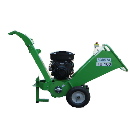
Page 4: Technical Characteristics For The Version With The Petrol Engine
TB 100 Technical characteristics for the version with the petrol engine Discharge chute STOP button Fuel tank Infeed chute Stand Engine controls Cutter unit TECHNICAL SPECIFICATION Petrol engine Chipping Capacity 4 to 6 m cuttings per hr depending on material Guaranteed wood diameter 80 mm Permitted wood diameter... -
Page 5: Technical Characteristics Of The Tractor-Driven Version
Technical characteristics of the tractor-driven version Discharge chute Drive belt cover Infeed chute Cutter unit A tree-point linkage TECHNICAL SPECIFICATION TB100 Tractor Chipping Capacity 4 to 6 m cuttings per hr depending on material Guaranteed wood diameter 80 mm Permitted wood diameter... -
Page 6: Technical Characteristics Of The Version With The Hydraulic Engine
Technical characteristics of the version with the hydraulic engine. Discharge chute Control lever Infeed chute Attachable loader (optional) TECHNICAL SPECIFICATION TB100 Hydraulic engine Chipping Capacity 4 to 6 m cuttings per hr depending on material Guaranteed wood diameter 80 mm... -
Page 7: Lifting Points
TB 100 Minimise noise by slowing to idle, or by stopping the engine whenever chipping is not in progress. CAUTION! Operators must wear appropriate ear protection. Bystanders must be kept away from machine’s proximity. Lifting Points Ensure the infeed chute is folded in and secured for transport. -
Page 8: Safety
TB 100 Safety ENSURE: 3.1.1 All Operators must be fully trained in the use of the machine. 3.1.2 The Operating Manual is read and understood. 3.1.3 The enclosed OSH guidance notes are read and understood. 3.1.4 Appropriate Personal Protective Equipment (PPE) is worn, including non-snag clothing, gloves, eye and hearing protection. - Page 9 TB 100 ALWAYS: 3.3.1 Check the machine before starting up (see Section 4 Preparation and Section 5.1 Operation: Pre-work checks). 3.3.2 Be aware of potential hazards in the work area, i.e. uneven ground, tree roots, trip/slip hazards, obstructions and type of materials being fed into the machine. 3.3.3 Feed from the side.
- Page 10 TB 100 Fig. 3.4.3 Infeed chute height Infeed chute height 600 mm 3.4 Safety controls and switches 3.4.1a Emergency Stop (Fig 3.4.1a) In the event of an emergency, push the STOP button. This will lock in position to stop the engine and the machine. 3.4.1c Emergency Stop (Fig 3.4.1c) In the event of an emergency, push the lever shown on the figure in order...
-
Page 11: Symbols On The Machine
TB 100 Symbols on the machine These relate to operator safety, correct use and maintenance of the machine. Check that all personnel understand and are familiar with the meanings before operating the machine. Read the Operating Manual Debris expulsion hazard. before starting up the Maintain a safe distance. - Page 12 TB 100 Make sure that both the machine data plate and the hazard warning stickers are clean and properly maintained at all times. Ask the manufacturer for the replacements, if required. Place the replacements in the original positions. It is strictly prohibited to have the hazard warning stickers mispositioned or removed altogether from the machine.
-
Page 13: Getting The Machine Ready For Work
TB 100 4.0 Getting the machine ready for work Fig. 4.1b Tractor coupling and PTO Upper link pin Fig. 4.1a Support and discharge chute STOP button PTO shaft Lower link pin Support 4.1a Initial fuelling and parking 4.1.1a Position the machine on the level ground and ensure the stand is secure (Fig 4.1a). - Page 14 TB 100 4.1.8b Connect the drive shaft to the tractor's PTO and then to the machine, whilst making sure that the direction of rotation is identical, as indicated on the shaft, until the buttons spring out into their correct locations. Secure all connection points with the safety chains.
-
Page 15: Pre-Work Checks
TB 100 5.0 Pre-work checks: Fig. 5.1.1 Support Fig. 5.1.2a Engine oil and fuel Fuel intake Support and Dipstick Fuel tap Fig. 5.2a Engine controls Fig. 5.3a Unblocking Air valve the rotor Start-up/stop Hole for rotor unblocking bar Throttle 5.1.1 Check the machine is stable with the support stand lowered and the pin in place (fig 5.1.1). -
Page 16: Starting Up The Machine
TB 100 5.2a Starting up the machine: 5.2.1a Check that all other personnel are clear of the machine. 5.2.2a Check that the machine STOP button is pulled out to start. 5.2.3a Turn the engine start switch to position I. (Fig. 5.2a) 5.2.4a Open the fuel tap by putting the vane to vertical. -
Page 17: Routine Maintenance Schedule
TB 100 6.0 Routine maintenance schedule Where applicable: (a) refers to the Engine Driven version; (b) refers to the Tractor driven version; (c) refers to the version with the hydraulic engine Note: Belt guard requires either a spanner or a hexagon key for removal. CAUTION! Always press the STOP button, switch the engine to position 0 and check for any rotation before carrying out any maintenance. - Page 18 TB 100 6.1 Lubrication points (see 6.14) Fig. 6.1a Lubrication points - petrol engine version 6.1.2 6.1.1 6.1.3 Fig. 6.1b Lubrification points - tractor driven version; hydraulic engine version 6.1.5 6.1.2 6.1.1 6.1.4 Machine lubrication points 6.1.1 Cutter bearing (remove guard) 1 nipple 6.1.2 Cutter bearing (non-drive end)
- Page 19 TB 100 6.2a Engine oil Fig. 6.2 Fuel intake and engine oil 6.2.1 Check daily (Fig. 6.2). dipstick Refer to the engine manual to refill. Fuel intake Oil intake Engine oil filter Refer to the engine manual for replacement. 6.3a Fuel level 6.3.1 Check daily before work and fill up, Dipstick as required (Fig.
- Page 20 TB 100 Replacement Fig. 6.7 6.5.5a Release the pulley bolt and slacken the tensioning screw to allow the drive belts to be removed (see section 6.5.3. - 6.5.4) 6.5.6 Fit the brand-new belts, ensuring they lie snugly in the pulley grooves. 6.5.7 Tension the belts, tighten the pulley.
- Page 21 TB 100 6.7.4b Place the stand under the cassette. 6.7.5b Lower the machine onto the cassette stand. 6.7.6b Remove 2 front bolts and 2 rear bolts. 6.7.7b Carefully raise machine release the cassette. 6.7 Blade servicing CAUTION! Take proper care. The blades are extremely sharp.
- Page 22 TB 100 Blade regrinding 6.12 Battery (if fitted) (Fig 6.12) Both edges of each blade must be ground First 50 hours and weekly on the front at the 27˚ angle and on the 6.12.1 Check the electrolyte level and top it back at the 10˚...
-
Page 23: Fault Finding
TB 100 6.14 Fault finding Fault Check Action Engine will not start STOP button Pull out to release Engine stop switch Push to I - start position Fuel Fill tank - check tap on Oil pressure Check oil level Drive guard Fit to engage cut-out switch Engine not at correct speed Engine throttle Check operation... -
Page 24: Warranty
After the delivery, check that the machine has not been damaged during transport. Any claims should be sent to “PERUZZO s.r.l.” in writing, no later than 8 (eight) days after receipt of the machine. The Warranty provides for only one-off exchange or repair of parts deemed to be faulty after close examination by “PERUZZO s.r.l.”... - Page 25 TB 100 Peruzzo srl Via Valsugana, 30 Curtarolo (PD) tel . 049.9620477 fax 049.9620435 P.iva 00712120286 peruzzo@peruzzo.it www.peruzzo.it PAG. 25 Cod. 29050055 Rev.01 Edit: 09/2015...
Need help?
Do you have a question about the TB100 and is the answer not in the manual?
Questions and answers