Table of Contents
Advertisement
I
n
s
t
a
l
l
a
t
I
n
s
t
a
l
l
a
t
1.
2.
Installation of components (powerbox, server, hub, monitor, capture box, 3G router)
3.
4.
5.
Updating the software a basic configuration
6.
Filling the Warranty certificate
Issue date: 15.03.2014
i
o
n
o
f
M
O
i
o
n
o
f
M
O
D
F
u
n
t
o
r
D
F
u
n
t
o
r
NM_FUNTORO_MOD SYSTEM_003_15032014_EN
o
s
y
s
t
e
m
o
s
y
s
t
e
m
Page 1 of 58
Advertisement
Table of Contents

Summary of Contents for Molpir MOD Funtoro FMS5711
- Page 1 Preparation Installation of components (powerbox, server, hub, monitor, capture box, 3G router) Cabling installation Checking the installation Updating the software a basic configuration Filling the Warranty certificate Issue date: 15.03.2014 Page 1 of 58 NM_FUNTORO_MOD SYSTEM_003_15032014_EN...
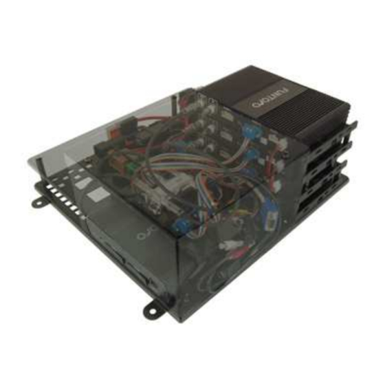
- Page 2 1. Preparation 1.1. components of MOD Funtoro system 1.1.1 MOD system server FMS5711 1.1.2 MOD system Hub FMS5718-01 1.1.4 1.1.3 MOD system Monitor 10“ FMS5722 MOD system Monitor 7“ FMS5723 1.1.5 MOD system Capture Box FMS5713 Issue date: 15.03.2014 Page 2 of 58 NM_FUNTORO_MOD SYSTEM_003_15032014_EN...
- Page 3 1.2. Tools required Except the ordinary tools, use crimping pliers for cable lugs, crimping pliers for connecting hub connectors. Avoid vehicle battery draining during the installation! 1.2.3 Insulation tape 1.2.5 Philips 1.2.4 1.2.1 1.2.2 screwdrivers Drills bits Battery Crimping pliers screwdriver 1.2.7 1.2.8...
- Page 4 1.4. installation material - cable ties, cable protection hoses, semicircular cable ducts (as needed) 1.4.2 1.4.1 Adhesive fastener Cable ties UVPS19HLK 1.4.1 – Cable ties Int.code length(mm) width(mm) color 502111 black 503140 black 502165 black 502200 black 503300 black 1.4.4 1.4.3 FMS208150 FMS208175...
- Page 5 1.4.5 – Spiral hose for wires protection Int.code Ø (mm) size (mm) 070494 1.4.6 Corrugated protection hose 1.4.6 – Corrugated protection hose Int.code Ø out. Ø in. Int.code Ø out Ø in. 1926653 1926666 18,8 15,2 1926654 1926667 21,0 16,8 1926656 1926669 24,0...
- Page 6 1.5. In the Warranty card form fill in basic installation data and information like Serial Number of the server, number of hubs, monitors connected to the respective HUBs, vehicle identification,.. Issue date: 15.03.2014 Page 6 of 58 NM_FUNTORO_MOD SYSTEM_003_15032014_EN...
- Page 7 1.6. Check the completeness of supplied material according to packing list 1.7. Check the integrity of the arretation elements of the cables 1.8. Mark numbers on all network GigaLAN cables connectors (light grey cables with rectangular connectors with 10 female PINs) with black permanent marker on both ends of the cable Figure 1.8.1 Figure 1.8.2...
- Page 8 FUNTORO Europe/MOLPIR prior the installation. In the case for installation are not used installation kits developed and supplied by FUNTORO Europe/MOLPIR or are used own or third party installation kits for Server, HUBs, monitors...
- Page 9 Figure 3.1.2 On the cables join (FMS-CA02-XXXXX with FMS-CA04-XXXXX) from hub to monitor use the secondary lock (068988-M) and fasten it with the cable tie (1.4.1.). FMS-CA02-XXXXX FMS-CA04-XXXXX Figure 3.1.3 068988-M FMS-CA04-xxxxx 068988-M FMS-CA04-xxxxx FMS-CA02-xxxxx FMS-CA02-xxxxx 068988-M FMS-CA04-xxxxx FMS-CA02-xxxxx FMS-CA02-xxxxx 068988-M FMS-CA04-xxxxx FMS-CA02-xxxxx...
- Page 10 Figure 3.1.5 CAUTION! Each wire coming out of Hub has to be firmly fixed with cable tie to the HUB bracket FMS037-Hxxxx !! – NOT TO THE SEAT OR VEHICLE STRUCTURE / BODY !! (fig. 3.1.5) Fix cables with Cable ties (Figure 1.2.7) or by fasteners (Figure 1.2.6) in such intervals, that cables don’t cause rattle noise while driving and free parts don’t suffer from vibrations Carrefuly crimp power wires (cable lugs, connector pins), use only recomended...
- Page 11 FMS037-S01 (vertical panel) Figure 3.2.1 Issue date: 15.03.2014 Page 11 of 58 NM_FUNTORO_MOD SYSTEM_003_15032014_EN...
- Page 12 Real Device Rate Function Fuse connection HUB 1 Switched power supply K1/1 HUB 2 Switched power supply K1/4 HUB 3 Switched power supply K1/7 HUB 4 Switched power supply K1/10 HUB 5 Switched power supply K1/13 HUB 6 Switched power supply K1/16 HUB 7 Switched power supply...
- Page 13 FMS037-S02 (horizontal panel) Figure 3.2.3 Issue date: 15.03.2014 Page 13 of 58 NM_FUNTORO_MOD SYSTEM_003_15032014_EN...
- Page 14 Real Fuse connection Amp Function Pin + Pin - Device HUB 1 Switched power supply K1/1 K1/2 HUB 2 Switched power supply K1/4 K1/5 HUB 3 Switched power supply K1/7 K1/8 HUB 4 Switched power supply K1/10 K1/11 HUB 5 Switched power supply K1/13 K1/14...
- Page 15 FMS037-S03 Figure 3.2.5 Issue date: 15.03.2014 Page 15 of 58 NM_FUNTORO_MOD SYSTEM_003_15032014_EN...
- Page 16 Real Fuse Device Function Pin + Pin - connection HUB 1 Switched power supply K1/1 K1/2 Switched power supply HUB 2 K1/4 K1/5 Switched power supply HUB 3 K1/7 K1/8 Switched power supply HUB 4 K1/10 K1/11 Switched power supply HUB 5 K1/13 K1/14...
- Page 17 NUMBERING OF HUBS FOR POWER SUPPLY AND NUMBERING FOR NETWORK GIGALAN MAY NOT MATCH Figure 3.6.2 3.7. Be sure that the GigaLAN cable from Gigaport 1 of the server is connected to a first hub to its Input port (Gigalan In connector is located on the same side as the connectors for connecting monitors).
- Page 18 3.8. Connecting GPS receiver Connect GPS receiver to the COM port connector of the ports wire harness of MOD server port COM2 (FMS-CA03-00300) according to the figure 3.9.1. Connect its USB connector with any USB connector of the wire harness FMS-CA03-00300 to power GPS receiver.
- Page 19 3.9. Engaging GPS receiver: Plug the wiring FMS-CA03-00300 into 2 MOD port (according the figure 3.9.1) and the other part connect to: - 9-pin connector RS-232 with 9-pin connector RS-232 on GPS receiver - USB connector with any USB connector on GPS receiver 15 PIN VGA 9 PIN RS232 FMS-CA03-00300...
- Page 20 Figure 3.9.3 CAUTION! Each wire coming out of the Server has to be firmly fixed with cable ties to Power Box FMS037-Sxx frame !! – NOT TO THE VEHICLE STRUCTURE / BODY !! (fig. 3.9.3) 4. Checking the installation 4.1. after turning on and the time of server booting (cca 2 min.) chceck the status LED on the server port Gigaport 1 - green LED should glow continuously, orange flash...
- Page 21 Figure 4.3.1 Issue date: 15.03.2014 Page 21 of 58 NM_FUNTORO_MOD SYSTEM_003_15032014_EN...
- Page 22 Figure 4.3.2 4.4. previous procedure repeat with all fuses, that are connected to other hubs (P2 ~ P12) 4.5. If in the vehicle is not seats numbering, use the numbering as shown in the warranty card (figure 4.3.1) 5. Updating software and basic configuration 5.1.
- Page 23 5.1.4. server will boot from USB flash memory and automatically turns on the process of recording the firmware. During this the LED „SYSTEM“ flashes continuously and LED on the USB and LED „STORAGE“ on the front panel of server is flashing (Figure 5.1.4.1) Figure 5.1.4.1 5.1.5.
- Page 24 switch “S1“, you have to wait, until it finishes booting (Figure 5.2.1.1) obrázok 5.2.1.2 and all monitors change to Stand-by – switch will be red (Figure 5.2.1.2) IF YOU HAVE ANY DOUBTS ABOUT THE CORRECT PROCESS OF FIRMWARE UPGRADE OR THIS PROCESS WAS ANYHOW INTERRUPTED, THEN REPEAT THE WHOLE PROCESS SINCE POINT 5.1.1 Figure 5.2.1.3 5.2.2.
- Page 25 Figure 5.2.4.1 5.2.4. after the monitors upgrade, on all monitors will automatically perform a re-boot (Figure 5.2.4.1) Figure 5.2.5.1 5.2.5. the main menu of the system will show up (Figure 5.2.5.1) Figure 5.2.6.1 5.2.6. remove USB memory from the server (Figure 5.2.6.1) 5.2.7.
- Page 26 5.3. basic system configuration For the option of recording the operation system status and subsequent analysis, quick elimination of possible malfunctions, it is necessary in any system to enter identification of the vehicle type, number of monitors in the seats, the date and time and to assign the MOD system multiple monitor seats in the vehicle.
- Page 27 Figure 5.3.1.3.1 5.3.1.3. hold and three times after each other press (Figure 5.3.1.3.1) Figure 5.3.1.4.1 5.3.1.4. software keyboard will show up. Enter password (normally 1359) and confirm by pressing (Figure 5.3.1.4.1) Figure 5.3.1.5.1 5.3.1.5. diagnostical menu will show up (obrázok 5.3.1.5.1) Issue date: 15.03.2014 Page 27 of 58 NM_FUNTORO_MOD SYSTEM_003_15032014_EN...
- Page 28 Figure 5.3.1.6.1 5.3.1.6. press icon „System“ (Figure 5.3.1.6.1) Figure 5.3.1.7.1 5.3.1.7. press icon (Figure 5.3.1.7.1) SETTING THE UTC (TIME AND DATE) – INFO Figure 5.3.2.3.2 Figure 5.3.1.8.1 5.3.1.8. pressing increases the value. Pressing decreases the value. where 1 column means – year, 2 column means – month, 3 column means – day Issue date: 15.03.2014 Page 28 of 58 NM_FUNTORO_MOD SYSTEM_003_15032014_EN...
- Page 29 Figure 5.3.1.9.1 5.3.1.9. confirm change – press (5.3.1.9.1) Figure 5.3.1.9.2 by pressing we return to the diagnostical menu 5.3.2 time setting Figure 5.3.2.1.1 5.3.2.1 press icon „System“ Issue date: 15.03.2014 Page 29 of 58 NM_FUNTORO_MOD SYSTEM_003_15032014_EN...
- Page 30 Figure 5.3.2.2.1 5.3.2.2 press icon SETTING A SHIFT OF LOCAL TIME COMPARED TO UTC! Figure 5.3.2.3.1 5.3.2.3 pressing increases the value. Pressing decreases the value where 1 column means – time zone (setting a shift of local time compared to UTC [Central European Time UTC+1, Central European Summer Time UTC+2]) 2 column means –...
- Page 31 Sometimes also called Zulu time, marked with the letter Z after the time data. UTC je the basis for civil time, different time zones are defined by their derivations from UTC. UTC is the basis of the measurement system as the sucessor to GMT (Greenwich Mean Time) and in informal expression is sometimes confused with it.
- Page 32 Figure 5.3.2.4.1 5.3.2.5 if we want to return to diagnostical menu on next screen 5.3.3. setting the identification of vehicle/system Figure 5.3.3.1.1 5.3.3.1 press icon „System“ Figure 5.3.3.2.1 5.3.3.2 press icon Issue date: 15.03.2014 Page 32 of 58 NM_FUNTORO_MOD SYSTEM_003_15032014_EN...
- Page 33 ENTER THE VEHICLE REGISTRATION NUMBER. IF A LICENSE NUMBER IS ASSIGNED INITIAL CHARACTERS PRODUCER ax. 10 characters) PRODUCTION NUMBER OF VEHICLE (m Figure 5.3.3.3.1 5.3.3.3 it displays a screen with software numeric keypad, to switch to the character keypad press icon (5.3.3.3.1) Figure 5.3.3.4.1 5.3.3.4...
- Page 34 5.3.4 setting the number of monitors in system Figure 5.3.4.1.1 5.3.4.1 press icon „System“ (5.3.4.1.1) Figure 5.3.4.2.1 5.3.4.2 press icon (5.3.4.2.1) Figure 5.3.4.3.1 5.3.4.3 Screen displays a software numeric keypad, where you insert the number installed monitors in vehicle (5.3.4.3.1) Issue date: 15.03.2014 Page 34 of 58 NM_FUNTORO_MOD SYSTEM_003_15032014_EN...
- Page 35 Figure 5.3.4.4.1 5.3.4.4 confirm change (5.3.4.4.1) Figure 5.3.4.5.1 5.3.4.5 if we want to return to diagnostical menu on the next screen (5.3.4.5.1) 5.3.5 Setting the seat number Figure 5.3.5.1.1 5.3.5.3 In the main menu press "Seat No" (5.3.5.1.1) Issue date: 15.03.2014 Page 35 of 58 NM_FUNTORO_MOD SYSTEM_003_15032014_EN...
- Page 36 FOR ASSIGNING A MONITOR TO PARTICULAR SEAT, USE ORIGINAL PRODUCTION NUMBERING (ON THE SEATS, ON THE SHELVES FOR LUGGAGE, ETC.). IF NUMBERING IS MISSING, PLEASE USE THE FOLLOWING NUMBERING SCHEME FOR: Two and more rows of seats One row of seats Figure 5.3.5.2.1 5.3.5.2 enter seat numer where you are sitting while working with a monitor in...
- Page 37 Figure 5.3.5.4.1 5.3.5.4 It will show (5.3.5.4.1) 5.3.6 Bulk appearance of numbers of all seats Figure 5.3.6.1.1 5.3.6.1. while monitor is Stand-by hold and three times press ON THE MONITOR, TO WHICH WAS NOT ASSIGNED SEAT NUMBER YET, IT IS NOT POSSIBLE TO START THE FUNCTION OF BULK SEAT NUMBERS ASSIGNEMENT IN MENU „DRIVER CONSOLE“...
- Page 38 Figure 5.3.6.3.1 5.3.6.3. this monitor goes into „Driver Console“ and displays its menu. Press icon „Tools“ (Figure 5.3.6.3.1) Figure 5.3.6.4.1 5.3.6.4. Press icon „Seat Number“ (Figure 5.3.6.4.1) Figure 5.3.6.5.1 5.3.6.5. Press icon „YES“ (Figure 5.3.6.5.1) Issue date: 15.03.2014 Page 38 of 58 NM_FUNTORO_MOD SYSTEM_003_15032014_EN...
- Page 39 Figure 5.3.6.6.1 5.3.6.6. all remaining monitors in system will turn on and on all monitors will display a software numeric keypad. Gradually on all monitors we set the number of seat corresponding to a particular monitor. After entering number on each monitor, confirm – press (5.3.6.6.1) WHILE ENTERING(ASSIGNING) MONITOR NUMBERS TO SEATS, PLEASE PAY ATTENTION TO ENTERING THE CORRECT DATA.
- Page 40 Figure 5.3.6.8.1 5.3.6.8. When all monitors have assigned the seat numbers on the monitor with „Driver Console“ in the main manu press icon „Reboot“ (5.3.6.8.1) Figure 5.3.6.9.1 5.3.6.9. all the monitors (except „Driver Console“) will be booting (figure 5.3.6.9.1) Figure 5.3.6.10.1 5.3.6.10.
- Page 41 Figure 5.3.6.11.1 5.3.6.11. turn off monitor with „Driver Console“ by pressing 5.3.6.12. turn off MOD system with the main switch „S1“ After turning on MOD system FUNTORO is ready for normal operation Issue date: 15.03.2014 Page 41 of 58 NM_FUNTORO_MOD SYSTEM_003_15032014_EN...
- Page 42 5.3.7 Chart of cabling Internal Code Cable Type Length FMS-CA01-00500 GigaLan 500mm FMS-CA01-02000 GigaLan 2000mm FMS-CA01-03000 GigaLan 3000mm FMS-CA01-03500 GigaLan 3500mm FMS-CA01-04500 GigaLan 4500mm FMS-CA01-05000 GigaLan 5000mm FMS-CA01-06000 GigaLan 6000mm FMS-CA01-07000 GigaLan 7000mm FMS-CA01-08000 GigaLan 8000mm FMS-CA01-10000 GigaLan 10000mm FMS-CA01-12000 GigaLan 12000mm FMS-CA01-15000...
- Page 43 FMS-CA06-03000 GigaLan 3000mm FMS-CA06-05000 GigaLan 5000mm FMS-CA06-07500 GigaLan 7500mm FMS-CA06-10000 GigaLan 10000mm FMS-CA07-15000 15000mm FMS-CA08-01600 1600mm FMS-CA09-00150 150mm FMS-CA10-00150 150mm FMS-CA11-00150 150mm FMS-CA12-00150 150mm FMS-CA13-00300 300mm FMS-CA14-00200 200mm FMS-CA15-01600 1600mm FMS-CA16-00200 200mm FMS-CA17-02000 2000mm FMS-CA18-00300 300mm FMS-CA19-00400 400mm FMS-CA20-00600 napájanie 600mm FMS-CA21-00600 napájanie...
- Page 44 Figure 5.3.8.2.1 5.3.8.2. in main menu press "Version" (5.3.8.2.1) Figure 5.3.8.3.1 5.3.8.3. in the second line from the top we can find the software version number (in this case 02.01.17) Figure 5.3.8.3.1 Issue date: 15.03.2014 Page 44 of 58 NM_FUNTORO_MOD SYSTEM_003_15032014_EN...
- Page 45 6. Instructions for filling out the waranty card The condition for recognition of European warranty is filling out the warranty card on webpage Funtoro at: http://www.funtoroeurope.com/extranet/prihlasenie Enter your „Login“ Enter your „Password“ Figure 1 WARNING! If you don’t make any change, system is set so, that after 30 minutes you will have to repeatedly enter „Login“...
- Page 46 Open window and enter number from the box Figure 4 Open the window „Server PN“ and fill out the offered data, which has to match with the label on the carton of the supplied server (see fig.n. 4) Window „Cable no. connected to port GIGABIT1“...
- Page 47 In the window „SSD disc capacity“ enter in GB the capacity of installed SSD disc into server If you don’t know the capacity of installed SSD disc, you will find out, when connected to capacity read from properties Figure 8 In the window „Software version“...
- Page 48 In the window „Amount of hubs“ enter the number of Hubs used in system Figure 11 Figure 12 Issue date: 15.03.2014 Page 48 of 58 NM_FUNTORO_MOD SYSTEM_003_15032014_EN...
- Page 49 In the window „Amount of monitor“ enter the number of types of monitors used in system Figure 13 Open „Monitor PN“ and enter number from monitor box Figure 14 In the window „Amount of monitors“ enter number of monitors from particular type Figure 15 In case we use more types of monitors, windows for other types fill according fig.14 and 15) Open „Capture Box type“...
- Page 50 Into window „Amount of capture boxes“ enter number of Capture boxes used in system Figure 17 Choose one of the options according condition Figure 18 *example: middle trunk Here describe *, where in bus is near left rear tire located server FMS5711 (or the whole Power Box FMS037-Sxx) Figure 19 Choose one of the options...
- Page 51 Choose one of the options Figure 21 Choose one of the options Figure 22 Choose one of the options Figure 23 Issue date: 15.03.2014 Page 51 of 58 NM_FUNTORO_MOD SYSTEM_003_15032014_EN...
- Page 52 Write all not mentioned external devices connected to the system as e.g..: camera, SAT receiver, DVD, Audio..obrázok 24 Here is place for notes to figures, or other important installation details *examples * SAT receiver in trunk above the passangerr seats behind the driver * GPS antenna on the dashboard at windshield...
- Page 53 In the window „Year of production“ enter date from production label of vehicle Figure 27 In the window „VIN no“ enter the VIN data from production label of the vehicle Figure 28 Issue date: 15.03.2014 Page 53 of 58 NM_FUNTORO_MOD SYSTEM_003_15032014_EN...
- Page 54 In the window „License plate“ enter vehicle registration number Figure 29 In the window „Operator“ enter the name of the company (operator), that will operate the vehicle Figure 30 In the window „Address“ enter street from the adress of operator Figure 31 Issue date: 15.03.2014 Page 54 of 58...
- Page 55 In the window „City/town“ enter city from the adress of operator Figure 32 In the window „ZIP code“ enter ZIP code from the address of operator Figure 33 In the window „Country“ enter country from the adress of operator Figure 34 Issue date: 15.03.2014 Page 55 of 58 NM_FUNTORO_MOD SYSTEM_003_15032014_EN...
- Page 56 In the window „Phone no“ enter phone number of the operator Figure 35 In the window „E- mail“ enter e-mail of the operator Figure 36 In the window „Operator“ enter name of installation center Figure 37 Issue date: 15.03.2014 Page 56 of 58 NM_FUNTORO_MOD SYSTEM_003_15032014_EN...
- Page 57 In the window „Address“ enter the street of installation center Figure 38 In window „City/town“ Figure 39 enter the city of installation center In the window „ZIP code“ enter the ZIP code from address of installation center Figure 40 In the window „Country“...
- Page 58 In the window „E- mail“ enter e-mail of the installation center Figure 43 In the window „Date of installation“ enter the last day of installation Figure 44 In the window „Place of installation“ enter place of installation Figure 45 inštalácie In the window „Date of registration“...
Need help?
Do you have a question about the MOD Funtoro FMS5711 and is the answer not in the manual?
Questions and answers