Table of Contents
Advertisement
Quick Links
Advertisement
Table of Contents

Subscribe to Our Youtube Channel
Related Manuals for Softing IT Networks Fiber Xpert OTDR 5000


Summary of Contents for Softing IT Networks Fiber Xpert OTDR 5000
- Page 1 ✗ Fiber pert OTDR 5000 MANUAL...
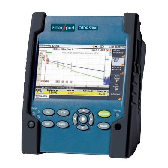
- Page 2 OTDR 5000 SOFTING IT NETWORKS GMBH FIBERXPERT OTDR 5000 Handheld OTDR designed for the construction, turn-up and maintenance of fiber networks User Manual...
- Page 3 European Union, all equipment purchased from Softing IT Networks GmbH after 2005- 08-13 can be returned for disposal at the end of its useful life. Softing IT Networks GmbH will ensure that all waste equipment returned is reused, recycled, or disposed of in an environmentally friendly manner, and in compliance with all applicable national and international waste legislation.
-
Page 4: Table Of Contents
OTDR 5000 TABLE OF CONTENTS ABOUT THIS GUIDE Purpose and scope Assumptions Technical assistance Conventions xvii CHAPTER 1 FiberXpert OTDR 5000 Overview Unpacking the instrument About the FiberXpert OTDR Main features Hard keys and Indicators Front panel hard keys Front panel indicators Power Supply CHAPTER 2 Safety information... - Page 5 Switching off the FiberXpert OTDR Resetting the FiberXpert OTDR First start: configuring your regional settings CHAPTER 4 Configuring the FiberXpert OTDR 5000 Displaying the System Settings Defining screen Backlight Contrast Screen Saver Defining the Audio parameters Defining the Automatic shutdown CHAPTER 5 Principle of Measurement Principle of reflectometry measurements...
- Page 6 OTDR 5000 CHAPTER 8 Configuring the reflectometry test Configuring the test in Expert OTDR Configuring the Acquisition parameters Parameters Launch cable parameters Configuring the Alarms parameters Configuring the Analysis parameters Parameters Measurement Configuring the Link parameters Configuring the file storage parameters Configuration in Test Auto mode Saving OTDR configuration in a file Loading an existing OTDR configuration...
- Page 7 Advanced functions in Expert OTDR mode Automatic measurement and detection Addition of events Manual measurements . Measurements of slope Measurement of ORL Measurement of Reflectance Splice measurements Memorization of the position of events . . Overlay trace function Overlaying several traces stored in memory Display of traces in overlay Adding traces in overlay .
- Page 8 Storing and reloading results File Setup Storing results. Loading results. CHAPTER 11 Scope Scope feature Overview Installation of tips Configuring the Softing IT Networks GmbH Scope Scope connection Configuring the Scope Test File Fiber Link Description Adding a new profile About page...
- Page 9 Loading a picture File menu Saving the test result in a jpg file CHAPTER 12 Transferring the FiberXpert OTDR 5000 Interface Establishing connection Connecting the FiberXpert OTDR 5000 and the PC Configuring the FiberXpert OTDR 5000 Transferring the Interfacen Virtual control buttons bar Equivalence between the keyboard and FiberXpert OTDR 5000 CHAPTER 13...
- Page 10 OTDR 5000 Sorting files Transferring files between two Platforms Establishing connection between two devices Transferring files Cancelling the connection Transferring files to a PC with the USB cable Establishing connection FiberXpert OTDR 5000 <-> PC Transferring files onto the PC Cancelling the connection Transferring files to/from a PC with a FTP server Direct connection...
- Page 11 Characteristics of reflectometry measurements Manual Measurement Typical specifications Ranges . . . Class of the lasers of the OTDR modules . OTDR modules measurement . . . Technical specifications of the Power meter function on module Technical specifications of the Source function on module Display specifications Screen Memory...
- Page 12 Installing a new version of the software Downloading from Internet Installation from a USB memory stick Launching the upgrade Checking new upgrade on Softing IT Networks GmbH Server Upgrading from the boot Install Option Enter Manually the Licence Import the license from the USB memory stick...
-
Page 13: Guide
ABOUT THIS GUIDE The FiberXpert OTDR 5000 of Softing IT Networks GmbH provides a handheld OTDR for the construction, turn-up and maintenance of fiber networks. The topics discussed in this chapter are as follows: – “Purpose and scope” – “Assumptions”... -
Page 14: Purpose And Scope
We are assuming that you have basic computer and mouse/track ball experience and are familiar with basic telecommunication concepts and terminology TECHNICAL ASSISTANCE If you need assistance or have questions related to the use of this product, call or e-mail Softing IT Networks GmbH’s Technical Assistance Center for customer support. Table 1... -
Page 15: Conventions
CONVENTIONS This guide uses naming conventions and symbols, as described in the following tables. Table 2 Typographical conventions Description Example User interface actions appear in this typeface. On the Status bar, click Start. Buttons or switches that you press on a unit appear Press the ON switch. -
Page 16: Fiberxpert Otdr 5000 Overview
1 Remove the FiberXpert OTDR 5000 and its accessories from the packing case. 2 Check that the module and accessories ordered are all there. If any part is missing or damaged please contact your local Softing IT Networks GmbH agent. The FiberXpert OTDR 5000 is delivered as standard with:... -
Page 17: About The Fiberxpert Otdr
About the FiberXpert OTDR 5000 The architecture of the FiberXpert OTDR 5000 is made of one Platform, to which a module is added to perform tests on fiber networks. The module is fitted to the FiberXpert OTDR 5000 The FiberXpert OTDR 5000 employs multi-tasking for the simultaneous performance of several operations: –... - Page 18 OTDR 5000 Fig. 1 FiberXpert OTDR 5000 with module TFT 5’’ Color Touchscreen Indicators Hard keys Loudspeaker Fig. 2 FiberXpert OTDR 5000: Front view RJ45 USB host Power Mini USB AC/DC Headset Meter Device Input jack Fig. 3 FiberXpert OTDR 5000: Connectors View...
-
Page 19: Hard Keys And Indicators
Fig. 4 Hard keys and Indicators HARD KEYS AND INDICATORS Front panel hard keys Table 2 Hard keys description HARD KEY FUNCTION Main on/off switch This button calls up the file explorer. It allows to: – choose the storage medium: internal memory, USB memory key. –... -
Page 20: Front Panel Indicators
OTDR 5000 Front panel indicators The FiberXpert OTDR 5000 is equipped with three indicators, lit into a different color according to the status of the unit. Table 3 Indicators Status On indicator The instrument, though connected to an external power source, is switched Blinking green off. - Page 21 Power supply plug Interchangeable plugs UK adaptable EUROPE JAPAN AUSTRALIA plug adaptable adaptable adaptable plug adaptable plug (installed by plug plug default)
-
Page 22: Safety Information
Do not use any mains adaptor or battery other than those supplied with the instrument, or supplied by Softing IT Networks GmbH as an option for this instrument. If another adapter or battery is used, it may damage the FiberXpert OTDR 5000 itself. -
Page 23: Laser Safety
– The proper operation of the instrument and its accuracy of measurement are dependent on the cleanliness of the environment and the optical connectors as well as the care taken in its manipulation. – The optical connectors must therefore be clean and dust-free. If the optical connection is not being used, protect the connections of FiberXpert OTDR 5000 using the protective caps. -
Page 24: Starting Up
OTDR 5000 3-STARTING UP Setting the adaptable plug to the mains adapter The FiberXpert OTDR 5000 is supplied as standard with a mains adapter and 5 country adaptable plugs (Europe / UK / US / Australia/Japan). To set the correct plug to the mains adapter: 1 Make flush the connector onto the mains adapter with the adaptable plug slots. -
Page 25: Charging The Battery
First use At the delivery, the battery is already set into the Unit, but its charge level is not «recognized» by the equipment. The icon is displayed on the upper banner of the screen. To get a valid indication of the battery, and be able to use correctly the Platform: 1 Charge fully the battery 2 Once fully charged, discharge the battery by keeping the Unit switched on, but not plugged to mains. -
Page 26: Switching The Fiberxpert Otdr 5000 On And Off
OTDR 5000 Once the battery is fully charged, the Charge indicator is lit in solid green. When the Charge indicator is blinking red, this mean the power supply is not compatible with the battery used. Charge is disabled. Charging the battery The battery capacity is superior to 75% The battery capacity is set between 50% and 75% The battery capacity is set between 25% and 50%... -
Page 27: Resetting The Fiberxpert Otdr
Switching off While the FiberXpert OTDR 5000 is operating, press the ON/OFF button to switch it off. NOTE When the instrument is switched off using the ON/OFF button, current results and configuration are saved. Next time the ON/OFF key is pressed, they are recalled. - Page 28 OTDR 5000 1 Click on Language and select the language to be used for the equipment. 2 Click on Date and enter the current date, using the numeric keypad displayed using the menu key Edit Number. 3 Click on Time and enter the current time, using the numeric keypad displayed using the menu key Edit Number.
-
Page 29: Configuring The Fiberxpert Otdr 5000
4-CONFIGURING THE FIBERXPERT OTDR 5000 This chapter describes the operations for configuring the instrument. The topics discussed in this chapter are as follows: – “Displaying the System Settings screen” – “Defining the screen parameters of the FiberXpert OTDR 5000” – “Defining the Audio parameters of the FiberXpert OTDR 5000” –... -
Page 30: Contrast
OTDR 5000 NOTE If you are in the Regional Settings page, and you press Exit, then the System Settings page automatically displays. Defining the screen parameters of the FiberXpert OTDR 5000 In the System Settings page, the following parameters can be defined: Backlight 1 Click on Backlight 2 Define the backlight level of the screen, using the left and right direction keys, or clicking... -
Page 31: Screen Saver
Fig. 10 Example of outdoor contrast Screen Saver Click on Screen Save if you wish to activate a screen saver to the equip- ment, to extend the life of the battery, in case the FiberXpert OTDR 5000 is not used for some time. Instead of the normal screen, a small animated picture of the Unit is displayed on the blackened screen. -
Page 32: Defining The Automatic Shutdown
OTDR 5000 Defining the Automatic shutdown of the FiberXpert OTDR 5000 The automatic shutdown function switches off the FiberXpert OTDR 5000 automatically if no operation has been performed and no key actuated for a period selected from this menu. Work in progress is automatically saved. The function for automatically switching off the FiberXpert OTDR 5000 is available only on battery operation, to save the battery 1 In the Utility box, click on Auto off parameter. -
Page 33: Principle Of Measurement
5-PRINCIPLE OF MEASUREMENT This chapter gives the principles of the measurements made by the optical modules. The topics discussed in this chapter are as follows: – “Principle of reflectometry measurements” – “Principle of optical power and attenuation measurements” Principle of reflectometry measurements Optical time domain reflectometry consists in injecting a light pulse into one end of the optical fiber to be analyzed and observing, at the same end, the optical intensity passing through the fiber in the opposite direc- tion to the propagation of the pulse. -
Page 34: Validity Of Measurement Itu-Reflectance
OTDR 5000 Validity of Measurement ITU-T ITU-T in recommendations G.650, G.651 and G.652, give backscatter measurement as an alternative method for measuring attenuation, the method of reference being the cut fiber. The field of application of backscatter is not limited, but the conditions for application of this method are nevertheless stipulated: –... -
Page 35: Principle Of Optical Power And Attenuation Measurements
PRINCIPLE OF OPTICAL POWER AND ATTENUATION MEASUREMENTS Power measurements A power meter, is all that is needed to measure emitted or received power: – to measure emitted power, connect the power meter directly to the output of the optical emitter; –... - Page 36 OTDR 5000 Accuracy of measurements – A high degree of accuracy is often required. It is then necessary to perform a preliminary calibration without the fiber under test to eliminate the losses due to connections as far as this is possible. To do this, use the «Reference Value» function.
-
Page 37: Starting Up
Always inspect and clean the connector end face of the optical fiber cable and the test port before mating both together. Softing IT Networks GmbH is not responsible for damage and reduced performance caused by bad fiber handling and cleaning. -
Page 38: Connecting Fiber Optic Cable To Test Port
Fig. 13 PC/APC bad connection Warning Softing IT Networks GmbH declines responsibilities of connector damages if a poor quality connector is used or APC to PC connections made. Test port connector repair will be charged Warning... -
Page 39: Adapter Types
Fiber Optic modules may come equipped with a universal connector and adapter selected at time of order. Adapter types Softing IT Networks GmbH offers 4 different adapters, all compatible with this connector, allowing the user to switch from one adapter to another according to which fiber type he intends to work with. - Page 40 OTDR 5000 Changing the adapter on a LA OTDR Module The LA modules are equipped with specific connector and adapters: 1 Unscrew the two screws of the adapter currently mounted onto the connector. 2 Remove the adapter 3 Set the new adapter vertically on the optical connector, making flush the «mark» on the adapter with the mark on the connector.
- Page 41 7-ACTIVATING OTDR FUNCTION Once the OTDR module is correctly set onto the equipment and FiberXpert OTDR 5000 is switched on, the desired OTDR function must be selected before any OTDR configuration, or measurement. The topics discussed in this chapter are as follows: SELECTING THE OTDR EXPERT FUNCTION Principle of the OTDR Expert The OTDR Expert is used to...
- Page 42 OTDR 5000 8-CONFIGURING THE TEST IN EXPERT OTDR Once the Expert OTDR icon is selected, the Results page automatically displays. In Expert OTDR, the parameters for acquisition and for file storage can be configured. 1 To call up the test configuration window, press the SETUP button. Dialog boxes and menu keys on the same screen enable selection of –...
- Page 43 Acquisition Select the kind of acquisition to be performed: Manual The acquisition parameters Pulse / Range / Resolu- tion can be set by user. Auto The acquisition parameters Pulse / Range / Resolu- tion are defined automatically and cannot be modi- fied The Measurement time will be set to Auto, but can be modified (see “Time”...
- Page 44 OTDR 5000 Predefined Select one of the acquisition times predefined: 10 seconds / 20 seconds / 30 seconds / 1 minute / 2 minutes / 3 minutes. Configuring the Alarms parameters In the Setup page, press Alarms softkey (if one parameter is selected in the current screen, press Top Menu soft key to display the right menu keys and click on Alarms).
- Page 45 Table 2 Multimode Modules (not available in SmartOTDR) Default TIA-568C ISO/IEC 11801 Splice Loss > 0.20 dB > 0.30 dB Connector Loss > 0.50 dB > 0.75 dB Slope 850 nm > 3.50 dB/km > 3.50 dB/km Slope 1300 nm >...
- Page 46 OTDR 5000 Predefined It is possible to choose one of the predefined values given for certain cables. The corresponding indices given in the table below are repeated on the screen. Wavelength (nm) 1310 SM 1360 - 1510 SM 1550 SM 1625 - 1650 SM Generic G652 G657 1.46750...
- Page 47 Fig. 17 Predefined index values (Multi Mode) Scatter coefficient User Selects for each wavelength, the backscatter coeffi- cient of -99 dB to -50 dB by increments of 0.1dB. Modification of the backscatter coefficient K changes the measurements of reflectance and ORL. Backscatter coefficients are selected automatically for each wavelength.
- Page 48 OTDR 5000 Splitters types Splitter 1: define the splitter type among the list: – 1x2 / 1x4 / 1x8 / 1x16 / 1x32 / 1x64 – 2x2 / 2x4 / 2x8 / 2x16 / 2x32 / 2x64 Splitter 2 and Splitter 3: define the splitter type among the list: –...
- Page 49 Configuring the Link parameters In the Setup page, press Link softkey (if one parameter is selected in the current screen, press Top Menu soft key to display the right menu keys and click on Link). NOTE The softkey Copy File/Link to all is displayed when one parameter is selected in the Link or File Setup page and when the Powermeter or Source function is active.
- Page 50 OTDR 5000 Fiber N Fiber N+1 Color Code <Fiber Name> Fiberx24 Fiberx24 Fiberx25 Fiberx25 <Fiber Code> Bl/Aq- 1/24 Gold/Bl Fig. 18 Example of incrementation of fiber code Change Fiber Nbr Increment the fiber number is automatically incremented at each new file-save. Decrement the fiber number is automatically decremented at each new file-save User defined...
- Page 51 Comment In contrast to the other data in this menu, the comment is specific to a fiber. This line is thus used to enter a new comment and not to display it. The comment appears at the top of the screen, with the other parameters of the fiber.
- Page 52 OTDR 5000 or, Press Default Filename to apply the name by default to the file: Fiber[Cable_Id][Fiber_Num]_[Lambda]_[Direc- tion][Pulse] The name of the file is displayed in grey under Filenaming parameter File Content In this parameter, select the file content for traces saving: One Trace in case of traces in overlay, each trace is saved in a distinct file (.sor extension).
- Page 53 ALARMS Alarms Thresholds None ANALYSIS Parameters Section Attenuation dB/km Index of Refraction G652 G657 Scatter Coefficient Auto Results on trace Graphics OTDR Connector Meas. Number of Splitters Splice None Auto Measurement Reflectance All Ghost No Fiber End Auto Bend Auto LINK Link Description Change Fiber Nr...
- Page 54 OTDR 5000 Directory into which file will be saved Fig. 20 Save Configuration file - Edition keypad 5 Press Enter to validate. A sound is emitted to indicate the file is saved. The configuration file is saved with the extension .fo_cfg (icon ) and can be recalled at any time from the Explorer page.
- Page 55 From the Setup page 1 Select one header in either Setup page (Acquisition, Link, File...) 2 Press Load Config. menu key. The file Explorer page displays 3 Select the configuration file desired 4 Press Load Config. to load the configuration file for acquisition in OTDR Expert mode. A sound is emitted to confirm the loading.
- Page 56 OTDR 5000 LAUNCHING A REFLECTOMETRY TEST AND DISPLAYING RESULTS Once the configuration for acquisition and file storage has been defined, the instrument is ready to launch an OTDR measurement. Pressing the START/STOP key is all that is needed to start or stop an OTDR measurement on the FiberXpert OTDR 5000.
- Page 57 – One of the connectors is dirty or badly connected. Replace the launch cable, make the connection again properly or clean the connector of the OTDR or of the jumper. – No fiber is connected. If the state of the connection is bad, it is still possible to carry out a measurement, but the results will not be very reliable.
- Page 58 OTDR 5000 The acquisition is carried out with the parameters previously selected in the Acquisition menu. It may be stopped at any time using the START/ STOP key. 1 Press the START/STOP key to start the acquisition. The red indicator goes on to show that the product is in process of acquisition and the screen displays the trace in process of acquisition.
- Page 59 Before launching a new OTDR acquisition, make sure the trace(s) displayed have been previously saved if necessary, as the new acquisition will automatically delete the displayed results. 1 On Results page: in Expert OTDR mode, press the softkey Quick Setup: the acquisition parameters that can be modified display under the results trace.
- Page 60 OTDR 5000 Actions on trace during acquisition During an acquisition, several actions are available on results in progress. Positioning Cursors A and B 1 Select Cursor A or Cursor B and: – Set both cursors A & B to control distance between two points. –...
- Page 61 Fig. 25 Example of acquisition in Real Time Zooming on the fiber end (in Real Time mode only) During a real time acquisition, you can reach the end of the fiber under test at any time: 1 Press Zoom to End menu key. The display automatically reaches the end of the fiber under test.
- Page 62 OTDR 5000 Results display The traces acquired or recalled from a memory are displayed on the Results page. According to the mode of acquisition (Expert OTDR or Smart Test), the results page offers similar functions, but also different functions. Fig. 27 Example of results trace with Smart Test Fig.
- Page 63 The trace can also be displayed with a dotted vertical line on the end of fiber. The icon is displayed on trace if the Receive Cable Start parameter has been defined in the Setup menu. The results of the measurements of attenuation, reflectance and slope can be marked on the trace.
- Page 64 OTDR 5000 – In ExpertOTDR mode, once Trace is selected, press validation key ( or ENTER) to pass from Trace + results table on 1 line to Trace + results table on 4 lines, and vice-versa The table with one line displayed under the trace gives the type and characteristics of the event nearest to the cursor.
- Page 65 The event underlined in yellow is the one the nearest of the cursor set on trace. To visualize an event, click on this event on the table to set the cursor on it onto the trace. Detailed description of an event Click on one event icon in the results table to display the event type and the alarm threshold defined for this event (if Alarms have been defined in the Setup page).
- Page 66 OTDR 5000 Positioning the cursor 1 Press the key to active the cursor. 2 Touch the screen on the required location on trace where the active cursor must be set. You can also use the direction keys and to move the selected cursor along the trace Above the trace is shown the 2-points loss measurement between the two cursors, together with the distance between the two cursors.
- Page 67 – If the Zoom/Shift key is selected, and the Zoom function valid, the upper banner indicates that to get an automatic or full zoom, you must press validation key ( or ENTER). Zoom function The Zoom function is used to analyze part of the trace in greater detail. The zoom is centered on the active cursor.
- Page 68 OTDR 5000 Specific functions of the zoom with a touchscreen With the touchscreen, once the Zoom function is selected on menu key Zoom, you can: – maintain your finger pressed on screen and shift the traces horizontally or vertically – position your finger on a cursor and move it on trace maintaining your finger pressed and moving it toward left or right –...
- Page 69 Fig. 34 Summary page & Alarms table In the lower part of the screen, the Alarms table, gives the summary of the alarms detected (Reflectances, Splices, Splitters, Connectors, Bends...). Select one event in the Alarm table and click on Event Diagnosis menu key or directly on the event icon in the Alarm table to get a detailed description of the event.
- Page 70 OTDR 5000 Selecting one trace from overlaid traces To make actions on a trace in overlay (move on events, set a cursor...), it must first be swapped with the active trace. To do this: 1 Press the Trace key 2 Press the direction keys and , as many times as necessary, until the active trace is displayed in green.
- Page 71 1 Press the Advanced key 2 Press the Modify meas.key, 3 Select Delete. 4 Press validation key ( or ENTER) The following procedure is then recommended: 1 By default, the instrument locates the events and proceeds to the measurements. 2 Addition of events in the cases of splices showing low attenuation and of close events. The FiberXpert OTDR 5000 then automatically measures the slope before and after the markers selected and measures the attenuation of the splice.
- Page 72 OTDR 5000 Hints on the positioning of markers – Do not add markers (with the Set Event key) after a manual measurement, as all the results will be recalculated automatically by the instrument. – If two markers are too close together, they will appear on the trace and the table but no measurement will be carried out on the second marker: to obtain results for this marker, a manual measurement is necessary.
- Page 73 Slope Fig. 38 Manual Measurement results Result of slope measurement The result is displayed on the screen between the two slope indicators [and]. The measurement results are also available in the table: 1 Press Exit to return to the initial results page. 2 Select Trace using Trace/Summary soft key 3 Press validation key ( or ENTER) to display results table under the trace.
- Page 74 OTDR 5000 Fig. 39 Result of ORL measurement ORL on a saturated trace If saturation occurs during an ORL measurement, the result is given with the sign <. This means that the actual ORL value is less than the value displayed. Measurement of Reflectance It is possible to carry out a reflectance measurement of a Fresnel for a reflective event.
- Page 75 Splice measurements There are two methods of carrying out manual measurements of splices on the trace: the two-cursor method and the five-cursor method. The five-cursor method is the more accurate, as it takes into account the difference of level between the slope before the splice and the slope after the splice. This method should be used whenever possible.
- Page 76 OTDR 5000 Memorization of the position of events To memorize the position of events with a view to repeating the measure- ments at the same place during a future acquisition or on another trace, press the Advanced key, then select Lock Evts.
- Page 77 Overlaying several traces stored in memory If an event is added (with the Set Events key) after manual measure- ments have been performed, then all the events on the trace will be converted into AUTO markers and an automatic measurement will be performed using these events. The previous manual measurements will be lost.
- Page 78 OTDR 5000 Swapping overlay traces Measurements can only be made on the active trace and not on overlaid traces. To make measurements on a trace in overlay, it must first be swapped with the active trace. 1 Press the Trace key, 2 Press the and direction keys, as many times as necessary, until the active trace is displayed in green.
- Page 79 Removing To change one reference trace into a «standard» trace, select it using the Trace/Event key, the reference and in the Advanced > Overlay menu, click once again on Set curve As Reference. trace(s) To change all the reference traces displayed into «standard» traces, whatever is the active trace, go in the Advanced >...
- Page 80 OTDR 5000 Saving the trace(s) and generating a report Once the results page is displayed, the trace(s) can be saved and a report can be generated directly from the results screen. The traces saving and report generation can have already been performed automatically if the parameter Auto Store was defined on Yes in the Setup screen with the appropriate Save Mode (file only or file + txt or + pdf).
- Page 81 NOTE The sor file and the txt or pdf file will have the same name. The icon displays during saving process. Once saving is completed, a sound is emitted onto the Platform. NOTE The file and the report are saved in the last storage media and directory selected. Saving and report for traces in overlay If several traces are displayed in overlay in the results page, one or several file(s)/report(s) is/ are generated:...
- Page 82 OTDR 5000 Fig. 43 PDF report...
- Page 83 10-POWER METER AND SOURCE OPTIONS OF THE OTDR MODULES A variety of options are available when ordering an OTDR Module. Option: The topics discussed in this chapter are as follows: – “Connection to the power meter” – “Configuring the Power meter” –...
- Page 84 OTDR 5000 The effect of this action will to be to bring the power meter into use. CAUTION The Powermeter icons of the singlemode port and the one of the Multimode port cannot be selected at the same time. When one is selected, it automatically deselects the other one. Configuring the measurement parameters of the power meter The measurement parameters can be accessed with the SETUP key.
- Page 85 Beep on Select if a sound must be heard when a modulation occurs (Yes / No) modulation Unit Unit of power displayed: Watt, dBm for displaying absolute power dB for displaying a result relative to a reference (link loss) Reference If dB units were chosen in the previous line, selection of the reference value for the level wavelength selected.
- Page 86 OTDR 5000 Select the parameter Fiber Number/Fiber Code and modify the parameter using the left and right direction keys. The fiber number can be automatically incremented/decremented at each new file save if it has been configured in the File Setup page (see NOTE The Fiber Code and the fiber number concatenated with Fiber Name are interdependent: they are incremented or decremented at the same time.
- Page 87 If this option is validated, it is possible, after selecting the extremity to be edited in the Cable Structure menu, to modify the values specific to the cable (cable name, color coding, content of the coding), for each of these extremities. To display/modify the data specific to the fiber (name and code), it is necessary to change direction temporarily.
- Page 88 OTDR 5000 Modifications made to the one are not automatically applied to the other. Thus, after the values relating to the origin have been modified, it is normal not to find these same values entered for the extremity. View If extremities are declared as different, this parameter allows to navigate between the extremity Extremity and Origin parameters.
- Page 89 – Code 1...23 Use the arrow to modify the codes if necessary. Operator Use the arrow to enter the name of the operator carrying out the measurement. Comment In contrast to the other data in this menu, the comment is specific to a fiber. This line is thus used to enter a new comment and not to display it.
- Page 90 OTDR 5000 Press Default Filename to apply the name by default to the file: Fiber[Cable_Id][Fiber_Num]_[Lambda]_[Direction] The name of the file is displayed in grey under Filenaming parameter Save Mode When a trace or more is displayed, in the parameter Save Mode, you can select three types of methods for storing traces: File Only only the trace(s) is/are stored in one/several file(s), with its extension (.sor, .msor)
- Page 91 Table of results For one and the same fiber, the power meter displays a table of 9 results corresponding to the different possible wavelengths. The table shows the power measured in dBm, the relative power (in dB) and the reference level in dBm (if units = dB), together with the mode. –...
- Page 92 OTDR 5000 – 270 Hz / 330 Hz / 1 kHz / 2 kHz – Auto (the sources emit on determined frequencies to enable the power meter to detect the wavelength used automatically) – TwinTest (cyclical emission on all available wavelengths for a few seconds on each wavelength), –...
- Page 93 It is important to set the zero of the power meter before making any measurements where accuracy is required, as the noise from the ger- manium photodiode fluctuates over time and with variations in temperature. Carrying out the reference Using two FiberXpert OTDR 5000 platforms with an OTDR module including a laser source option and a Power meter option, an insertion loss measurement in continuous wave can be performed.
- Page 94 OTDR 5000 Use the arrow keys or touchscreen to select the Powermeter function in Home page. Press RESULTS key In the Results page, press Pow.Reference > Standard Ref. The actual power level is set as the new reference level for the selected wavelength. Then, the displayed value is around 00.00 dB.
- Page 95 11-SCOPE The scope function is a hot-plug feature enabled directly when inserting a Softing IT Networks GmbH microscope supplied as an option: The topics discussed in this chapter are as follows: – “Scope feature” – “Installation of tips” – “Configuring the Microscope”...
- Page 96 Various tips, patchcords and bulkheads types, are available Configuring the Microscope Scope connection 1 Plug in your Softing IT Networks GmbH scope into a USB port of the FiberXpert OTDR 5000. 2 Push the button Home 3 Validate the Scope function 4 Connect probe with the fiber being inspected.
- Page 97 Profiles contain the analysis parameters by which PASS/FAIL criteria are determined. Once the line is selected, you can also add a new profile, clicking on the Add Button On the line Tip, select the tip set onto the microscope to connect fiber for inspection. Capture This parameter allows to select the action of the Quick Capture button onto the Scope button...
- Page 98 OTDR 5000 On the line Fiber Number, use the numeric keypad, which will display by clicking on the right arrow key, to enter the fiber number. On the line Change fiber Nbr, select if the fiber number must be modified after each results saving: No: the fiber number is not modified at each saving Increment;...
- Page 99 Starting up with the scope Once the FiberScope icon is validated: 1 Press RESULTS hard key Sharpness level Fig. 55 Example of the result using the microscope Use the Focus Control button onto the microscope to adjust the image quality and sharpness. NOTE To switch from Scope page to FO results page and vice-versa, press the RESULTS hard key for about 2 seconds (a beep is emitted).
- Page 100 OTDR 5000 Launching a test of the connector and fiber end-face Once the display is correctly adjusted (magnification, sharpness...), a test of fiber connector can be launched. To launch the test: 1 Press Test key to launch the test of plugged fiber connector. The test is completed: –...
- Page 101 Overlay The Overlay key allows, when selected, to display the limits of each zone and to display with colors the defaults on the image. When the key is deselected, the zones and defaults are not graphically identified. This function is also available in Mosaic Mode. Mosaic Mode It is possible to display only one picture in full screen (640 * 390 pixels) or up to four pictures (320*180 pixels each, including the live camera picture) in mosaic mode.
- Page 102 OTDR 5000 High mag./ allows to modify the live display from high to low magnification and vice-versa Low mag. Picture selected: Image Comment allows to add a comment to the selected picture Save allows to save the selected picture in the directory Scope, in the disk of the Unit. Press Save key, enter a name for the jpg file and validate.
- Page 103 File menu Saving the test Once the test has been performed, and the result is displayed on the FiberXpert OTDR 5000 result in a jpg screen: file 1 Press FILE key 2 Click on Save key to save a jpg file of the test result on the disk of the FiberXpert OTDR 5000.
- Page 104 OTDR 5000 12-TRANSFERRING THE FIBERXPERT OTDR 5000 INTERFACE The FiberXpert OTDR 5000 can be used in combination with a PC in order to transfer the Unit Interface onto a PC, or to access the internal memory or USB memory stick contents on the PC. Topics described in this chapter are as follows: –...
- Page 105 Configuring the FiberXpert OTDR 5000 1 In the Home page of the FiberXpert OTDR 5000, validate the Settings icon. 2 In the System Settings page, in the I/O Interfaces box, configure the following parameters: Remote Screen Remote = Session or Permanent must be confirmed in both cases, in the Interface E/S window. screen the screen cannot be remote on to a PC or on to another FiberXpert OTDR 5000.
- Page 106 OTDR 5000 NOTE Once the FiberXpert OTDR 5000 is connected to the network, the icon indicates the connection is working. Proxy > Use proxy 1 Select No if no proxy is used. 2 If Manual has been selected, enter the Proxy Address. 3 If Auto has been selected, enter the Pac Address.
- Page 107 Click to install TightVNC software on your PC (not mandatory) Fig. 61 VNC window You can use keyboard mouse of the PC to control the FiberXpert OTDR 5000 NOTE Once Remote screen is accessible via VNC, the icon displays on the upper banner of the screen until the connection is cut or the FiberXpert OTDR 5000 is switched off.
- Page 108 OTDR 5000 Equivalence between the keyboard and FiberXpert OTDR 5000 The PC keyboard can replaced all the buttons and keys of the FiberXpert OTDR 5000 except the ON/OFF button: – The menu keys to the right of the screen are replaced by the function keys F1 to F6. –...
- Page 109 13-WEB BROWSER The FiberXpert OTDR 5000 allows to access to internet, using the Web Browser installed on the equipment. The topics discussed in this chapter are as follows: – “Configuring the Web access” – “Starting the web browser” – “Creating bookmarks” –...
- Page 110 OTDR 5000 Fig. 64 Web Browser page Opening an internet page Once the Web Browser is displayed, you must enter the internet address. 1 Set the cursor in the address bar: a Use the mouse connected via USB port on the FiberXpert OTDR 5000 or the mouse of the PC if the screen is deported via VNC application on the PC, or use the touchscreen.
- Page 111 Creating bookmarks Once a page is opened, you can apply it a bookmark, in order to get a shortcut toward this page. Once the internet page for which a bookmark must be created is opened: 1 Click on to open the dialog box for bookmarks creation.. A new tools bar is displayed on the right of the screen.
- Page 112 OTDR 5000 Click on the menu key to go back to the web browser. NOTE The web browser will open a PDF document, not a URL including a PDF file. The PDF is also automatically saved on the disk of the Platform. Leaving the web browser Depending on how long you want to leave the web browser and on your connection mode, you may:...
- Page 113 14-FILE MANAGEMENT The files management with the FiberXpert OTDR 5000 can be performed, whether a module is set onto the FiberXpert OTDR 5000 or not. The topics discussed in this chapter are as follows: – “File Explorer Overview” – “Directories and Files selections” –...
- Page 114 OTDR 5000 2 Click on the arrow at the left of the directory name, or press validation hard key, display the sub-directories if any. Access to Selected directory sub-directory Sub-directory Fig. 68 Directory selection Files selection To select one or several files from the explorer page: 1 Press on files that must be selected.
- Page 115 1 Select the directory / the file(s). 2 Press Edit menu key 3 Press Copy to keep the directory / file(s) to their initial location. or, Press Cut to delete the directory / file(s) from their initial location 4 On the left of the screen, select the directory; or select the new storage media. 5 Click on Paste menu key.
- Page 116 OTDR 5000 3 If you want to create a sub-directory, select the directory into which it must be created. 4 Press the right menu key Create Directory. The edition keypad displays 5 Enter a name for this directory 6 Press Enter key to validate the new directory Opening files Once a file is selected, press Load menu key.
- Page 117 Sorting files Whether files are selected or not, the key Sort allows to access to a sub-menu allowing to sort the file according to pre-defined parameters: – Sort by name: the files display in an ascending order (from A to Z). If you click once again on the key, the files display in a descending order (from Z to A).
- Page 118 OTDR 5000 2 Once connection is established, confirm that you wish to activate the USB link in the pop- up window on the FiberXpert OTDR 5000. Fig. 72 Confirmation of files export via USB cable Transferring files 1 On the distant Unit, open the File Explorer page The usbflash driver appears on the left side of the screen.
- Page 119 Transferring files to a PC with the USB cable If some Results traces or other kinds of file need to be transferred to the PC, this can be easily done using a USB cable. Establishing connection 2000 1 Connect the FiberXpert OTDR 5000 to a PC, plugging the USB cable on the mini USB port of the Unit toward a USB port on the PC.
- Page 120 OTDR 5000 3 Click on the message and select «Open folder to view files» in the dialog box Softing IT Networks GmbH DISK (F:) («F:» is an example, it can be different according to your PC and to the USB port used). Fig.
- Page 121 Cancelling the connection Once all desired files have been transferred onto the PC, connection between FiberXpert OTDR 5000 and PC can be removed: 1 On the PC, use the appropriate method to safely remove the USB cable from the USB port. The screen displays the results trace of the active function, or returns to the Home page if no function is active.
- Page 122 OTDR 5000 Fig. 78 Internet Protocol h Click on Ok and close all the dialog boxes opened onto the PC. 3 On the FiberXpert OTDR 5000 Unit, in the System Setup page, under I/O interface > Ethernet, select Dynamic. IP Address of the Unit Fig.
- Page 123 use Dynamic attribution mode (DHCP). In this case, the address of the FiberXpert OTDR 5000 (10.33.18.235 in the example) is displayed but cannot be altered. 4 Wait for about ten seconds while the connection is established. 5 On the PC, make sure that the connection is operational by selecting Start > Execute... and typing ping followed by the address of the FiberXpert OTDR 5000.
- Page 124 OTDR 5000 Creating a screenshot You can create captures of what is displayed on the screen, directly from the FiberXpert OTDR 5000. Configuring the parameters of screenshots To configure the screenshot and choose the format of the generated file: 1 Press HOME hard key 2 Select the Settings icon to reach the System Settings page.
- Page 125 Logo to be displayed on the upper right of the page: a Press to open the edition keypad b Enter the path of the logo file with its extension (example: disk/Softing IT Networks GmbH logo.jpg) c Press Enter to validate.
- Page 126 OTDR 5000 Creating the report 1 Open the file to be saved in a report in JPG, PNG or PDF format 2 If necessary, make the modifications on the file/trace (see user manual part of the OTDR Modules for OTDR trace files). 3 Set the trace view as wished.
- Page 127 Fig. 83 Example of report (in pdf) Merging pdf or txt files In the Explorer page, two pdf/txt files or more, generated via the results traces can be merged in one pdf file. – The pdf files that can be merged are those generated via the Fast Report key on trace results page or via the Export key on the upper banner (or left and right arrow keys) –...
- Page 128 OTDR 5000 The file is automatically saved in the same directory as the one where files have been selected. It gathers all results from pdf/txt files selected (and traces for pdf file), in one single pdf file of several pages (1 results screen per page, if the results table does not exceed one page). NOTE Once merged file is saved, it can be renamed in the Explorer Storage media...
- Page 129 The USB memory stick can then be disconnected from the Unit’s USB port. NOTE The USB memory stick can also be removed using the Expert Tools > Media Utilities menu, accessible via the System Settings page. See “Maintenance and Troubleshooting” if any problem occurs with the USB memory stick Cloud Storage Principle and prerequisites of the Cloud Storage The Cloud storage defined the outsourcing of data on distant servers, which avoid the data...
- Page 130 OTDR 5000 Configuration on Cloud server Configuration on FiberXpert (example with CloudSafe) OTDR 5000 Fig. 85 Example of configuration Connecting Cloud Storage Once configuration has been established on the FiberXpert OTDR 5000, it is ready to be connected with Cloud server: Select one parameter of the Cloud Storage window on FiberXpert OTDR 5000 1 Press Connect Cloud Storage menu key .
- Page 131 Transferring files using Cloud Storage Once connection between FiberXpert OTDR 5000 and cloud storage server is successfully established, the files can be transferred from one Unit to the other. 1 Press HOME hard key. 2 Press FILE Explorer on the Home page In the Explorer page, a new storage media is available: cloud- storage.
- Page 132 OTDR 5000 15-TECHNICAL SPECIFICATIONS This chapter contains the technical specifications of the FiberXpert OTDR 5000 mainframe. The topics discussed in this chapter are as follows: – “OTDR modules on FiberXpert OTDR 5000 – “Technical specifications of the Power meter function on module” –...
- Page 133 Automatic – Automatic measurement of all the elements of the signal. Slope measurement by least measurement squares or 2 points of measurement. – Display threshold of faults: - 0 to 5.99 dB in steps of 0.01 dB for event thresholds - -11 to -99 dB in steps of 1 dB for the reflectance - 0.01 to 5.99 dB in steps of 0.01 dB for attenuation –...
- Page 134 OTDR 5000 d. ADZ measured at +/- 0.5 dB on the basis of a linear regression using a -40 dB type reflectance, at shortest pulse width. e. ADZ measured at +/- 0.5 dB on the basis of a linear regression from a reflectance of type FC/UPC (-55 dB) at shortest pulse width, at 1310 nm.
- Page 135 Single / Multi mode Singlemode Power meter Multimode Power meter Measurement Wavelength 1310 / 1490 / 1550 / 1625 / 1650 850 and 1300 nm Calibrated Wavelength 1310 / 1490 / 1550 / 1625 / 1650 850 and 1300 nm Accuracy at calibrated wavelengths ±...
- Page 136 OTDR 5000 Display specifications Screen – Backlight high visibility color touchscreen – Size: 5 inches – Resolution: 800 x 480 pixels Memory – Standard memory: internal memory, with a capacity of 1GB (with a minimum of about 125 Mb are available for data storage). Input/Output –...
- Page 137 Mains adapters Supply or Power assigned in AC and in DC: 25 W Dimensions - Weight Weight 692 g 1.52 lbs FiberXpert OTDR 5000 without options, battery nor module 1.21 kg 2.67 lbs FiberXpert OTDR 5000 with a Li-Polymer battery and one OTDR LM Module 172 g 0.37 lbs Li-Polymer battery...
- Page 138 OTDR 5000 Bumps The FiberXpert OTDR 5000 resists the following test: – 1,000 bumps per axis along each of the 3 axes, with power off. – Jolts of 15g, 1/2 sine, duration 6 ms, at 1 second intervals. Vibration The FiberXpert OTDR 5000 resists the following vibration tests: –...
- Page 139 Maintenance work on this instrument must only be undertaken by qualified personnel using suitable equipment. In most cases, it is advisable to contact the nearest Softing IT Networks GmbH Service Centre, which will undertake the appropriate troubleshooting and repair work.
- Page 140 OTDR 5000 Cleaning the optical – Squirt a highly volatile solvent (such as isopropylic alcohol) into the connector. connections of – Blow out the connector using a clean dry air supply from an aerosol can fitted with an the FiberXpert extension.
- Page 141 Fig. 88 Software Options page Services Data page This page allows to display information about the elements inside the FiberXpert OTDR 5000 (CPU, Memory, hardware revision, screen reference...). 1 Once on the About screen, press Services Data menu key to display the list of elements contained on your FiberXpert OTDR 5000.
- Page 142 When the software is obtained from the Internet, it must be saved on a storage medium before the software upgrade of the product can be carried out. To do this: 1 Open Internet Explorer 2 On the Softing IT Networks GmbH web site (http://www.Psiberdata.com), open the page of the product concerned – FiberXpert OTDR 5000 3 Click on the tab Downloads.
- Page 143 Installation from a USB memory stick You must be equipped with a USB memory stick with a minimum capacity of 128 MB. Before installing the upgrade, you must format the USB memory stick 1 Once formatted, disconnect the USB memory stick from the FiberXpert OTDR 5000 Unit using the key Eject USB in the Media Utilities page.
- Page 144 OTDR 5000 Launching the upgrade Whatever is the method selected for upgrade (Server, USB key...) and once the list of the software versions available is displayed next to the versions installed on the FiberXpert OTDR 5000 follow these instructions to launch the upgrade: 1 Click on Show Prev choice or Show Next Choice to display the previous and next versions available.
- Page 145 Install Option This page allows to import the licence to get a software option. Licence Code Fig. 92 Example of a License file (.lic) To import the license, you can either enter manually the licence code, given in the license file, (.lic file) or import this file with a USB memory stick connected to the FiberXpert OTDR 5000.
- Page 146 OTDR 5000 Fig. 93 Enter the Licence code The license file can be opened via a word processing software such as Word... The challenge code must be entered exactly as it is in the .lic file, paying attention to the lower-case and upper-case letters etc.
- Page 147 Fig. 94 License imported 6 At the end of this sequence you will be asked to reboot the unit to apply the modifications, pushing the key 7 Confirm the reboot Locking the FiberXpert OTDR 5000 The FiberXpert OTDR 5000 can be locked at any time: 1 In the HOME page, click on Expert Tools 2 Click on Instrument Lock Out 3 Confirm the FiberXpert OTDR 5000 locking by clicking on Confirm (or use the Cancel key...
- Page 148 The screen automatically displays the HOME page. Returning an instrument To return an instrument get in contact with Softing IT Networks GmbH to follow the appropriate RMA process When returning an instrument, it is essential to indicate the following minimum information: –...
- Page 149 Waste Electrical and electronic Equipment (WEEE) Directive In the European Union, this label indicates that this product should not be disposed of with household waste. It should be deposited at an appropriate facility to enable recovery and recycling. Troubleshooting Troubleshooting Solution Nothing happens when the ON/ OFF key is pressed.
- Page 150 OTDR 5000 If the stick needs to be formatted, proceed as follows: 1 Insert the memory stick into one of the USB port on the top of the FiberXpert OTDR 5000. 2 Press the HOME button 3 Validate the Settings icon to open the System Settings page. 4 On the right menu keys, successively select Expert tools >...
- Page 151 If you meet problems during the Unit functioning, or if the battery does not charge anymore when plugged, this may require the battery to be replaced. CAUTION Battery is not interchangeable in the field. It must be replaced by Softing IT Networks GmbH. Please contact support.
- Page 152 Softing IT Networks GmbH.Upon delivery of such product, Softing IT Networks GmbH shall assume the risk of loss or damage until that time that the product being repaired or replaced is returned and delivered to customer. Customer shall pay all transportation costs for equipment or software shipped to Softing IT Networks GmbH for repair or replace- ment.
- Page 153 INDEX About page 131 Accessories 125 Adapter specifications 121 Attenuation accuracy of measurement 26 Battery charging time 17 specifications 120 Bluetooth pairing 113 remove pairing 118 search devices 114 specifications 124 Cleaning optical connectors 10 plates, housings and screen 130 Connectors cleaning 130 CSV file 71 Environment 122...
- Page 154 OTDR 5000 JPG,JPEG file 72 Licenseenter manually 140 import from USB 141 License file 71, 140 Memory capacity 120 Module fitting and removing 14 MSOR file 71 Optical connectors precautions 10 OTDR file 71 PDF File 71 Power meter alarm 28 attenuator compensation 27 connection 26 file management 32 measurement 31 reference 126 reference measurement 30 results 28...
- Page 155 Screenshot 79 Services data 132 Software update via Ethernet 134 via Internet 133 via USB 136 Storage media 84 abbreviations 88 Text file 71 Transfer interface ethernet Mode 53 proxy config. 54 remote screen 52 Unpacking the instrument 2 Unit access to the internal memory 76 assembly 14 dimensions 121 indicators 5 locking 142...
- Page 156 Softing IT Networks Adressen Template: North America & Canada Softing Inc. Knoxville, Tennessee Phone: +1.865.251.5252 E-mail: sales@softing.us Asia/Pacific Singapore Softing Singapore Pte. Ltd. Singapore Phone: +65-6569-6019 E-mail: asia-sales.itnetworks@softing.com China Softing Shanghai Shanghai Phone: +86-21-54133123 E-mail: china-sales.itnetworks@softing.com Europe/Middle East/Africa Germany Softing IT Networks GmbH...
Need help?
Do you have a question about the Fiber Xpert OTDR 5000 and is the answer not in the manual?
Questions and answers