Table of Contents
Advertisement
Quick Links
Advertisement
Table of Contents

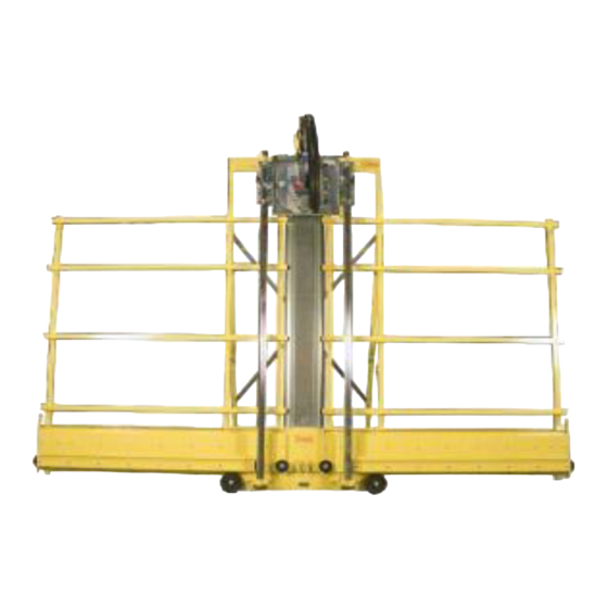
Summary of Contents for SAW TRAX C52VP
-
Page 2: Table Of Contents
Table of Contents P arts Diagram ................... 2 I nstallation & Set Up ................3 M oving the unit ................. 3 O pen & secure the folding stand ............. 3 L owering side stand legs .............. 3 I nstalling Retraction Mechanism ............. -
Page 3: P Arts Diagram
P arts Diagram 1. Retraction Mechanism with spool 2. Cord Holder 3. Guide tube bracket (top & bottom) 4. Guide tubes -2 5. Dust pan 6. Folding Stand 7. Hinge for folding stand – 2 8. Cross brace for folding stand 9. -
Page 4: I Nstallation & Set Up
I nstallation & Set Up M oving the unit a. Once you uncrate the unit you will need to transport it to a location where you will set it up. To roll the unit, tilt it vertically so the wheels make contact with the ground &... -
Page 5: A Djusting The Tension Of The Retraction Spool
c. On the carriage, lift the pins by pulling up and twisting a 1/4 turn. The pins will stay in the up position so you may insert the saw into the carriage. Remove the saw insert from the box and place it into the carriage by placing the base of the plate on the bottom lip of the carriage (make sure the cord is facing the top of the plate as pictured) Next, tilt the plate inward until the plate is completely inserted. -
Page 6: A Ttaching The Cord Holder
A ttaching the cord holder a. Remove the cord holder that is attached to the folding stand. (see step 2) Cord Holder Rod b. Remove one washer and one nut. The rod should still have 1 nut & washer tightened to the end of the threads. c. -
Page 7: Attaching The Dust Brush
c. Make sure the dust cover of the saw is positioned above the motor. (As in the Picture) d. Place the saw so the saw blade is touching your piece of material. (Make sure the blade guard is out of the way) e. -
Page 8: C Autions & Warnings
C autions & Warnings A saw manual is included with your purchase. Follow all instructions that are included in your power tool manual. Stay alert, watch what you are doing & use common sense. Always use Safety protection such as glasses, earplugs, dust mask & closed toe shoes. -
Page 9: G Eneral Use Instructions
G eneral Use Instructions Inserting/removing tool plates in the carriage a. On the carriage, lift the pins by pulling up and twisting a 1/4 turn so that pins stay in the up position so you may insert the tool into the carriage. -
Page 10: Rip Cutting Material
Rip cutting material a. Set your tool in the horizontal position. b. Use the rip gauge pointers to set cutting height. c. Set and secure the tools cutting height by tightening the Carriage locks. d. Insert the material to cut. e. -
Page 11: M Aintenance And Care
M aintenance and Care Keep unit free of dust build- up. Periodically blow dust from all moving parts, including the rollers that support the material. Make sure you are using the appropriate blade for the material you are cutting. Sharpen saw blade on a regular basis. Should the frame’s coating get scratched, use touch-up paint to prevent exposed metal from rusting. -
Page 12: T Rouble Shooting & Faqs
T rouble Shooting & FAQs YES THESE ARE REAL QUESTIONS WE HAVE RECEIVED OVER THE YEARS What is this red or black thingy? It is your trigger lock for rip cutting. It keeps the saw motor running. (See General use - rip cutting instructions) How do I keep my saw ON so the blade will spin continuously on so I can rip cut? Use the red or black thingy, known as the trigger lock. -
Page 13: W Arranty
The saw motor is covered by the saw manufacturer’s warranty and is not covered by SawTrax Mfg.Co., Inc. In no event shall Saw Trax Mfg. Co., Inc. be liable for any indirect, incidental or consequential damages from the sale or use of this product. This disclaimer applies both during and after the duration of this warranty. -
Page 14: A Ccessories - Installation & Use
A ccessories – Installation & Use - Instead of cutting small pieces on the bottom rollers of the M id-Fence machine, use the mid fence to hold small pieces. This allows for Base plate easy waist high cuts. a. This accessory is Pre-installed b. -
Page 15: S Heet Clamp
S heet Clamp - Is used as an extra hand to hold material in place so you don't have to. It is especially handy with cutting long narrow pieces on the material rollers or long pieces on the mid fence. Hinge a. -
Page 16: F Rame Dust Collection
a. Loosen the bolts that attach the “hat” bracket to the aluminum extrusion until you can slide them out of the groove & off the extrusion. b. Place the “hat” bracket over the vertical square tubing from the Flip stops backside of the frame. -
Page 17: P Ivoting Knife Plate
a. This plate may be inserted in a horizontal or vertical cutting position. (see General use - changing inserts section) b. Move entire knife bracket close to the material by loosening the wing nut located under the triangle frame. Then retighten the wing nut. -
Page 18: F Loating Router Plate
– This insert will allow you to use a router to make F loating router Plate consistent depth dados. Frame a. Installing the handle- 1. Remove both nuts from the J-shaped handle and set aside for later use. 2. Fit the J-shaped handle (open end face up) between the arm and the router insert frame. -
Page 19: W All Mounting System
- Used to permanently attach your unit to a wall. W all Mounting System a. You will need to provide two 2x4 boards, each 4 feet long. All mounting brackets, screws and a nut driver are included in this accessory package. If you have a folding stand on your unit you will need to remove it.
Need help?
Do you have a question about the C52VP and is the answer not in the manual?
Questions and answers