Table of Contents

Summary of Contents for Palax C900
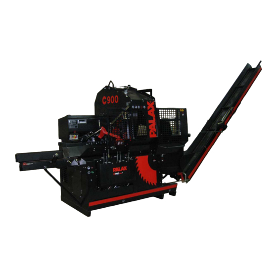
- Page 1 Instruction manual Palax C900 Powered by tractor Powered by electric motor SERIAL NUMBER _______________________ YEAR OF MANUFACTURE _______________________ PALAX Lahdentie 9 FI-61400 Ylistaro, FINLAND Tel. +358 6 4745100 www.palax.fi...
- Page 2 1-2017 Translation...
-
Page 3: Table Of Contents
1-2017 CONTENTS Foreword ..........................5 EU Declaration of Conformity..................... 6 Intended use of the machine ....................7 Warning signs ......................... 7 Nameplates ........................... 9 The main dimensions and models of the machine ............10 Safety instructions ......................10 Noise emission and vibration ................... 11 Responsibilities of the operator .................. - Page 4 1-2017 Cutting to equal length and feeding into the splitting chute ........23 Feeding the last log for splitting ..................24 Disturbances during crosscut operation and their remedy ......... 24 Crooked trees ........................24 Big trees..........................24 Cutting of small trees without splitting ................24 Disturbances during the splitting operation and their remedy ........
-
Page 5: Foreword
The operator is also obliged to gain familiarity with the operating controls of the machine and the emergency stop mechanism. For more infor- mation about our products, please visit our website at www.palax.fi. NOTE ! Keep this manual with the machine at all times. -
Page 6: Eu Declaration Of Conformity
Ylistaron Terästakomo Oy www.palax.fi Lahdentie 9 FI-61400 Ylistaro Finland +358 6 474 5100 The person in charge of Technical Construction File: Kai Koskela, kai.koskela@palax.fi Product: Palax C900 a firewood processor with 4,3-m discharge conveyor Powered by: Tractor PTO or electric motor... -
Page 7: Intended Use Of The Machine
1-2017 1.3 Intended use of the machine This firewood processor with conveyor is intended to be used for production of firewood from round timber. Use of the machine for any other purposes is prohibited. Maximum size of the wood: For cutting, the maximum diameter of the tree is about 37 cm. The maximum length of the log is 4-5 m. - Page 8 1-2017 Read the instruction manual: Do not wear loosely hanging clothes: Use eye guards and hear- ing protectors: Wear safety shoes: wear work gloves Lifting point of the ma- chine The protective net for the splitting chute cannot be opened un- less the crosscut saw-blade is in its upper position Emergency stop Direction of rotation of the blade/PTO...
-
Page 9: Nameplates
1-2017 Disconnect the machine from Beware of rotating blade Stay away from The machine may the electric sup- moving parts of the only be operated by ply before taking machine one person to any service measures Stopping the func- Reversing the in- Sawing Feeding with tions of the machine... -
Page 10: The Main Dimensions And Models Of The Machine
1-2017 Output 15 kW 1.6 The main dimensions and models of the machine Models C900 DRIVING POWER TR/SM Weight 1,450 kg 1,550 kg Height/width/length Transport position 2.55 m / 1.4 m / 2.83 m In-feed conveyor Length 2.2 m Height 0.9 m Diameter of blade/hole 900 mm/ 40 mm Max. -
Page 11: Noise Emission And Vibration
All the safety-related devices are necessary to ensure a sufficient level of safety. The C900 is a very safe machine provided that the instructions supplied are properly followed, the regular maintenance routines are duly executed and the work is carried out without haste. -
Page 12: Operating Conditions
Consult your dealer about matters related to the warranty. 1.12 Operating instructions for the winch Please refer to the user manual of the winch or visit our website at www.palax.fi for more detailed operating instructions for the winch. Translation... -
Page 13: Taking Delivery And Setting Up The Machine For Operation
1-2017 2 TAKING DELIVERY AND SETTING UP THE MACHINE FOR OPERATION 2.1 Lifting the machine The machine can be lifted with a forklift truck from both sides. The places for the lifting forks are marked with decals. There is also a lug for lifting the machine on the upper part of the machine frame. -
Page 14: Bringing The Table Extension Into The Work Position, Fig. 2
1-2017 7. Splitting chute 8. Operating panel 9. Hydraulic connectors for log-table 2.5 Bringing the table extension into the work position, Fig. 2 1. Disconnect the rubber strap A. 2. Pull open the locking lever B. 3. Swing the conveyor down and place the leg into the opening C in the frame. Re-con- nect the rubber strap. -
Page 15: Bringing The Conveyor Into The Work Position, Fig. 5
1-2017 WARNING! Always hold by the winch handle as you lower the conveyor. 2.7 Bringing the conveyor into the work position, Fig. 5 1. Lower the conveyor to the ground and connect the support bar B for the conveyor chain (Fig. 5). 2. -
Page 16: Adjusting The Cutting Length, Fig. 6
1-2017 2.8 Adjusting the cutting length, Fig. 6 The machine is equipped with a special Palax Optimi cutting length adjuster, which ad- justs the stroke length of the splitting cylinder in accordance with the desired cutting length. Adjust the cutting length using the control lever (OPTIMI, Fig.11) and the scale on the machine’s frame (Fig. -
Page 17: Disengagement Lever For Transmission, Fig. 7
1-2017 If the angular gear revolutions and the cutting speed of the crosscut blade are suffi- cient, less load will be subjected to the transmission. 3.4 Disengagement lever for transmission, Fig. 7 The machine is equipped with a special device for disengaging the transmission be- tween the angular gear and the machine to make the hydraulic pumps and the crosscut saw-blade stop. -
Page 18: Starting The Electric Motor Using The Y/D Starter, Fig. 8
1-2017 When starting up the machine, check that the direction of rotation corresponds to the arrow on the blade cover. To check the direction of rotation, run the motor for a short while and then stop it sud- denly. The direction of rotation is reversed using the phase-switch in the appliance inlet. The machine may only be connected to a power supply equipped with a fault current switch of 30 mA. -
Page 19: Emergency Stopping Of An Electrically Powered Machine, Fig. 8
1-2017 3.9 Emergency stopping of an electrically powered machine, Fig. 8 Push down the emergency stop button D. Turn the pushbutton clockwise to release it. 3.10 The machine is equipped with a system to prevent simultaneous op- eration in two modes, Fig. 9 When the cover plate B is turned down, it is possible to connect the extension cord. -
Page 20: Electric Heater For Oil Tank
As the protective net for the splitting chute is opened, the crosscut saw-blade cover is activated and the operation of the cross- cut saw-blade, the pusher, the wood length adjuster (Palax Optimi) and the adjustment of the splitting wedge are impeded. -
Page 21: Other Hydraulic Operating Controls, Fig. 11
6. Additional operation, if provided 7. Control lever for the log-deck Use the operating lever for the Palax Mega log-deck to operate the stepfeeder and the transfer chains on the deck. 8. Adjustment of discharge conveyor speed ( Fig 11A ) Speed control valve is located on the top of the discharge conveyor hydraulic motor Use this knob for adjustment of the discharge conveyor speed. - Page 22 1-2017 Fig. 11A Fig. 11B Translation...
-
Page 23: Use Of The Firewood Processor, Crosscut Operation
1-2017 5 USE OF THE FIREWOOD PROCESSOR, CROSSCUT OPERATION NOTE ! The machine is intended for operation by one person only. Never leave the machine, which is easy to start, unattended. 5.1 Operating the crosscut saw, before the operation Cleanse the new circular saw-blade of any protective grease, because a greasy blade ac- cumulates resin easily, making it heat up, lose its tension and start to jerk. -
Page 24: Feeding The Last Log For Splitting
1-2017 5.4 Feeding the last log for splitting Feed the last log the usual way to the splitting chute as soon as the pusher has re- turned to its rear position. Start the splitting movement manually. WARNING! Make sure that the tree always remains under the clamp during cutting. The minimum length for the log is 25 cm. -
Page 25: Disturbances During The Splitting Operation And Their Remedy
1-2017 7 DISTURBANCES DURING THE SPLITTING OPERATION AND THEIR REMEDY 7.1 Stuck wood As the logs are big and have big branches, the cylinder force may not be sufficient. If the log sticks to the wedge, reverse the cylinder using the manual control. Raise the splitting-wedge and retry the splitting using the manual control. -
Page 26: Accessories For The Firewood Processor
1-2017 8 ACCESSORIES FOR THE FIREWOOD PROCESSOR 8.1 Splitting cylinder The C900 model can be equipped with a splitting cylinder of 5.6 tons or 8 tons or a PowerSpeed cylinder of 8.0 tons . 8.2 Automatic high-speed valve The Palax C900 is equipped with automatic high-speed valve as standard. The valve reduces the splitting speed only when the pressure exceeds 120 bar. -
Page 27: Maintenance Of The Machine
NOTE ! Always use genuine spare parts prescribed by the manufacturer. NOTE ! To clean up the guide rails for the pusher, drive the Palax Optimi once a day to its extreme position (55 cm) and after that, return it to the desired cutting length. -
Page 28: Tightening The V-Belts
1-2017 9.2 Tightening the V-belts The Palax C900 is equipped with automatic tightening devices for the belts. 9.3 Replacement of the V-belts, centre shaft / saw-blade shaft 1. Remove the crosscut blade as instructed in point 9.1. 2. Slacken the tightening device of the belt. -
Page 29: Tightening The In-Feed Conveyor Belt, Figs. 18 And 19
1-2017 9.8 Tightening the in-feed conveyor belt, Figs. 18 and 19 There are tightening screws A and B at the end of the infeed deck table extension, which can be used for tightening the belt. As you tighten the belt, make sure that the belt travels in the centre of the roller. Ensure that the scraper C is as close to the roller as possible. -
Page 30: Replacing The In-Feed Conveyor Belt
1-2017 9.9 Replacing the in-feed conveyor belt 1. Remove the bearing of the pusher on the operator’s side from the frame. 2. Remove the cover, Fig. 20 3. Remove the support plate, Fig. 21 4. Remove the old belt from its place. 5. -
Page 31: Change Of The Hydraulic Oil
1-2017 9.12 Change of the hydraulic oil The normal hydraulic oil volume is 80 litres. In professional use, the oil volume can be 120 litres. The quality of oil should be ISO VG 32, e.g. Univis 32, SHELL Tellus 32, NESTE HYDRAULI 32 or equivalent. -
Page 32: Servicing The Main Valve, Fig. 26
1-2017 9.14 Servicing the main valve, Fig. 26 To withstand and operate flawlessly, the detent end A, the spool shifter joint B and the ball joint of the control valve require regular lubrication. Lubrication of the valve is par- ticularly important if the machine is to be left standing for several months. If the parts of the detent have become rusty, the machine will not operate flawlessly. -
Page 33: Structure Of The Detent End And The Correct Order Of The Parts, Fig. 27
1-2017 9.15 Structure of the detent end and the correct order of the parts, Fig. 27 Keep cover C of the detent end depressed while opening screws C, as the stiff springs can throw the cover off. This can also make the springs and balls of the detent fly off. In connection with assembly of the detent end, apply a small amount of Vaseline to holes A of the detent. -
Page 34: Maintenance Schedule
1-2017 10 MAINTENANCE SCHEDULE Object Task Daily Service in- Service Service Material /Method terval interval interval 100 h 500 h 1000 h Angular gear Check SAE 80 0.5 l 1 Change 2 Change Hydraulic oil Check Volume 80 l Normal conditions 1 Change E.g. -
Page 35: Malfunctions And Their Remedy
1-2017 11 MALFUNCTIONS AND THEIR REMEDY Disturbance Cause Remedy The crosscut saw-blade is heavy 1. The blade is dull. 1. Sharpen the saw-blade. 2. Too much resin in the blade. on power and gets hot. 1. Clean the blade. The saw-blade wobbles. 1. -
Page 36: Electric Diagrams
1-2017 12 ELECTRIC DIAGRAMS Translation... - Page 37 1-2017 Translation...
Need help?
Do you have a question about the C900 and is the answer not in the manual?
Questions and answers