Table of Contents
Advertisement
Quick Links
STUART
Installation, Operatation & Maintenance
Instructions
Please leave this instruction booklet with the home owner as it contains important guarantee,
maintenance and safety information
Read this manual carefully before commencing installation.
This manual covers the following products:
BEP 130
Pt. No. 46727
BEP 150
Pt. No. 46728
1
CE compliant product
Advertisement
Table of Contents

Summary of Contents for Stuart Turner BEP 130
- Page 1 Please leave this instruction booklet with the home owner as it contains important guarantee, maintenance and safety information Read this manual carefully before commencing installation. This manual covers the following products: BEP 130 Pt. No. 46727 BEP 150 Pt. No. 46728...
-
Page 2: Table Of Contents
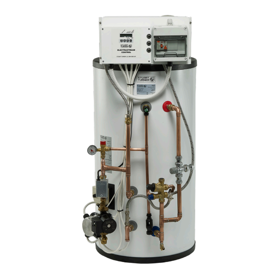
PRODUCT DESCRIPTION The Electrastream unit is a packaged hot water and central heating unit designed to provide hot water and wet heating to water filled radiators, using electricity as the primary fuel. The Electrastream is a 9 kW (30,000 btu) system suitable for flats, apartments, offices and other small dwellings. - Page 3 WARNINGS: DO NOT remove or adjust any component part of the unvented water heater: contact the INSTALLER. Plumbing must remain as supplied, do not add to or change any plumbing or connections. In the event of hot water/steam being emitted at the discharge pipe or tundish, switch the system off and contact installer –...
-
Page 4: Checklist
CHECKLIST IMPORTANT: With the appliance removed from its packaging check for any damage prior to installation. If any damage is found contact Altecnic Ltd within 24 hours of receipt. Fig. 1 Item Description Item Description 22 mm lever isolating Electrastream unit valve Cont... -
Page 5: Locations
Building Regulations. Cylinder *Weight *Weight Capacity Model Empty Full O 576 BEP 130 130 litres 1200 mm 957 mm 49.5 kg 179.5 kg BEP 150 150 litres 1325 mm 1085 mm 54.5 kg 204.5 kg... - Page 6 The location and position of the water conditioner should be as per the manufacturer’s recommendations. Check water pressure & flow rates: Stuart Turner recommends 1.5 bar pressure at 20 litres/minute flow rate as the minimum requirements for satisfactory operation. The unit will still operate below this, but it may not be possible to run two or more outlets at the same time.
- Page 7 System layout schematic: Mains electrical supply Isolating valve Single check valve Cold supply (not supplied) to taps 3.5 bar pressure reducing valve (not supplied) Water conditioner Incoming mains supply Isolating valves Mains stopcock Hot supply to taps and thermostatic showers Heating flow to radiators/ kickspace...
-
Page 8: Key Features
2 KEY FEATURES Heating expansion Hot water expansion vessel 8 litre vessel 12 litre Schrader valves (under caps) Important: Plumbing must Temperature remain as supplied. sensor (in box) Do not add or change any plumbing or connections. Over temperture cut-out thermostat Note: Image shown with cables removed Tricore heater 3 off... -
Page 9: Pipework Connections
3 PIPEWORK CONNECTIONS Hot/cold services: The cold water mains supply is connected to the combination valve via the lever isolating valve supplied, which limits incoming pressure to 3.5 bar and has an integral NRV. The hot water outlet pipework is connected to the outlet of the mixing valve via the lever isolating valve supplied. - Page 10 The discharge pipe (D1) from the vessel up to and including the tundish is supplied by Stuart Turner Ltd. Where otherwise the installation should include the discharge pipe(s) (D1) from the safety device(s). In either case the tundish should be vertical, located in...
- Page 11 Where a single common discharge pipe serves more than one system, it should be at least one pipe size larger than the largest individual discharge pipe (D2) to be connected. The discharge pipe should not be connected to a soil discharge stack unless it can be demonstrated that the soil discharge stack is capable of safely withstanding temperatures of the water discharged, in which case it should: a) Contain a mechanical seal, not incorporating a water trap, which allows water into...
- Page 12 Worked example and pipe sizing: The example below is for a G½ 6 with a discharge pipe (D2) having 4 No. 22 mm elbows and length of 7 m from the tundish to the point of discharge. From Table 1: Maximum resistance allowed for a straight length of 22 mm copper discharge pipe (D2) from a G ½...
-
Page 13: Electrical Installation
4 ELECTRICAL INSTALLATION Regulations: The electrical installation must be carried out in accordance with the current national electrical regulations and installed by a qualified person. 4.2 Before starting work on the electrical supply ensure power supply is isolated. 4.3 DO NOT allow the supply cord to contact hot surfaces 4.4 DO NOT switch the power on until the unit has been filled with water and has been earthed. - Page 14 4.10 Wiring of the unit: The Electrastream Unit is supplied wired, therefore only a mains cable (not supplied) is required to be installed through the cable gland located at the top of the RCD box. This 3 core cable suitably sized is connected into the live, neutral and earth of the RCD.
- Page 15 Cont... - 15 -...
-
Page 16: Commissioning
5 COMMISSIONING IMPORTANT it is the responsibility of the installer to ensure that the Electrastream System is properly commissioned. Should the commissioning not be carried out, then the manufacturers guarantee and any extended warranty, will become null and void. Wet System 5.2 System flushing: The pipework system should be flushed out prior to the Electrastream being connected to ensure any contaminants/chemical residues and foreign bodies are removed from elsewhere in the system. - Page 17 f) Test the operation of the Temperature & Pressure relief valve by turning the manual test cap and ensure the water flows freely and safely to waste. g) Test the operation of the combination valve PRV by turning the manual test cap and ensure the water flows freely and safely to waste.
- Page 18 5.11 Overview of control unit: For display settings see Fig. 12 For error displays see 8.1 HEAT 1 Indicates Eleement 1 is ON HEAT 1 ! Indicates heater element has failed – see 5.17 HEAT 2 Indicates Eleement 2 is ON HEAT 2 ! Indicates heater element has failed –...
- Page 19 For error displays see 8.1 Fig. 12 Electrastream control unit – display settings Cont... - 19 -...
- Page 20 6 GENERAL OPERATION 6.11 Heating motorised valve: When the room thermostat is calling for heat and the Electrastream control unit is set for heat ON, the heating motorised valve will open allowing water to the radiators. Display icon ‘Valve V’ indicates valve is open 6.12 Pump: The heating circulating pump is controlled by Electrastream Control Unit in response to the room thermostat.
- Page 21 6.17 Temperature & pressure relief discharge: Note: The Tundish or discharge pipe should remain visible, do not box in or cover up. The Electrastream hot water cylinder has a Temperature/ Pressure relief valve (TPRV); in the event of the pressure within the cylinder becoming too high, the TPR valve will vent. The heating system has its own Pressure relief valve (PRV) and in the event of the pressure within the heating system becoming too high, the PRV will vent.
- Page 22 6.21 Setting heat and hot water requirements: Figure below shows a 24 hour clock with typical use of the Electrastream during ‘Off- Peak’ economy 10 settings. Note:- Self Test – After 3am each day the unit carries out a self test period for approx. 30 minutes.
- Page 23 This manual and supplements must be left with the end user together with a copy of the completed guarantee form. 6.23 For further technical support: Phone the Stuart Turner TechAssist team on +44 (0) 800 31 696 80. Our staff are trained to help and advise you over the phone.
-
Page 24: Maintenance/Servicing
The Electrastream system should have a routine service at least once in 12 months to optimise its safety, efficiency and performance. c) Only use genuine Stuart Turner. The use of other parts will invalidate the warranty. IMPORTANT: Always turn off the heating system and electricity supply to the system –... - Page 25 Replacing the TRI-CORE heater: When replacing the Tri-core heater the relays on the Electrastream Control Unit must be checked for operation – 1. Heat cylinder 2. Observe the control unit and wait for the actual temperature to reach the set target (65 °C) 3.
-
Page 26: Technical Specification
8 TECHNICAL SPECIFICATION BEP 130 BEP 150 Pump Model 46727 46728 General Guarantee 1 year Approvals Cylinder capacity 130 litres 150 litres Features Coils Single ERP rating Performance Maximum water supply pressure 12 bar Operating pressure 3.5 bar Coil rating... -
Page 27: Trouble Shooting
Problem with mains supply Check mains supply – it may have been interrupted discoloured Check water conditioner (when fitted) is operating correctly. Hot water discoloured Damage to coil Cylinder coils may be fractured, consult Stuart Turner Ltd. Cont... - 27 -... - Page 28 Water/Steam being User to.. seen at the discharge Turn off the system at the isolator or consumer unit. pipe or tundish Turn on a hot tap until it runs cold to reduce the pressure and temperature. Turn on the radiators – ensuring all thermostatic valves are open.
-
Page 29: Guarantee
10 THE ELECTRASTREAM GUARANTEE Congratulations on purchasing a Stuart Turner product. We are confident this product will provide many years of trouble free service as all our products are manufactured to the very highest standard. All Electrastream products are guaranteed to be free from defects in materials or... - Page 30 - 30 -...
- Page 31 - 31 -...
- Page 32 Stuart Turner Ltd, Henley-on-Thames, Oxfordshire RG9 2AD ENGLAND Tel: +44 (0) 1491 572655, Fax: +44 (0) 1491 573704 info@stuart-turner.co.uk www.stuart-turner.co.uk Issue No. 3619/1–02 Pt. No. 20908...
Need help?
Do you have a question about the BEP 130 and is the answer not in the manual?
Questions and answers
Error code 4 how do I reset
i have ERROR 4 in the display, do not know what it relates to