
Related Manuals for Duplex Jeti DS-12

Summary of Contents for Duplex Jeti DS-12
- Page 1 computer radio control system CZECH REPUBLIC DS-12 2.4GHz & 900MHz NG Dual Band System FW 5.00...
- Page 2 computer radio control system...
-
Page 3: Table Of Contents
computer radio control system 4.3.3 Control Stick Tension Adjustment ........17 1. Introduction ................... 09 4.3.4 Ratchet Tension Adjustment ..........18 1.1 DS-12 ....................09 4.3.5 Throttle stick travel adjustment ........19 1.2 Activation method for software modules of JETI model ..09 1.3 Features ..................... - Page 4 9 . 0 . 1 Pa s s w o r d p r o t e c t i o n a g a i n s t a c c i d e n t a l 8. Duplex Receivers ..................42 configuration changes ..............
- Page 5 computer radio control system 9.1.1 Model Selection ..............54 9.2.7 Ailevator Function ............... 76 9.1.2 New Model ................55 9.2.8 V-Tail Mix ................. 77 9.1.3 Basic configuration- AIRPLANE ......... 56 9.2.9 Delta/Elevon Mix ..............78 9.1.4 Basic Configuration - HELICOPTER ........57 9.2.10 Butterfly Mix .................
- Page 6 computer radio control system 9.3.10 Voice Commands ............100 9.6.1 Configuration ..............118 9.4 Timers/Sensors ................103 9.6.2 Servo & Range Test ............. 121 9.4.1 Timer ..................103 9.6.3 View Inputs ................121 9.4.2 Alarms ................... 105 9.6.4 Receiver Output (Servo Monitor) ........122 9.4.3 Vario ..................
- Page 7 computer radio control system 10.3 Sounds, Alarms & Acoustic Updates ........131 12.5 Delta/Elevon Mix ................138 10.4 System Backup ................132 12.6 Spoilers to Elevator Mix ............. 138 10.5 PC Joystick ..................132 12.7 Ailerons to Rudder Mix ..............139 10.6 Telemetry Data Logging .............
- Page 8 computer radio control system...
-
Page 9: Introduction
„16 procedure for displaying telemetric data. digit registration code” (xxxx- The DUPLEX EX family of products have been equipped with an xxxx-xxxx-xxxx) (see the menu improved real-time telemetry system which can be viewed on the „System ->... - Page 10 computer radio control system the relevant amount. After payment, a unique nontransferable file named “Activation.bin” will be generated. It will then be sent to your e-mail. Connect the DS-14 to your computer and enable USB mode. Copy the “Activation.bin” file to the transmitter SD card into the root folder.
-
Page 11: Features
DS-12 case for protection against mechanical 1.3 Features damage. Duplex 2.4GHz – the DS-12 transmitters feature the Duplex 2.4GHz, Large Memory – Internal SD card for storing models, sounds, and frequency hopping, digital, data stream system, originally telemetry data. -
Page 12: Manual Navigation
computer radio control system 1.4 Manual Navigation 1.5 Technical Support If you feel uncertain about how to set up particular transmitter To make navigation faster, the DS-12 transmitter Instruction Manual functions, do not hesitate to take advantage of our technical support: has been divided into 5 basic groups: Web Site Either the JETI model (manufacturer) or your local distributor’s web sites... -
Page 13: Package Contents
1.6 DS-12 Package Contents 2 System Specifications JETI DS-12 Transmitter, Wall Power Supply, USB PC Cable, Installation Key Set (HEX 1,5; TORX 10) Cleaning Cloth, Instruction Basic technical parameter DS-12 Manuals, RF module 900MHz (863-870 MHz - EU) -
Page 14: Help Mode
computer radio control system This help mode is available in FW min. v5.00. We recommend update 3 Help mode your transmitter by Jeti Studio. It is possible to call up the help mode for each item where a "question mark" icon appears in the upper right corner of the screen . -
Page 15: Description Of Transmitter Ds-12
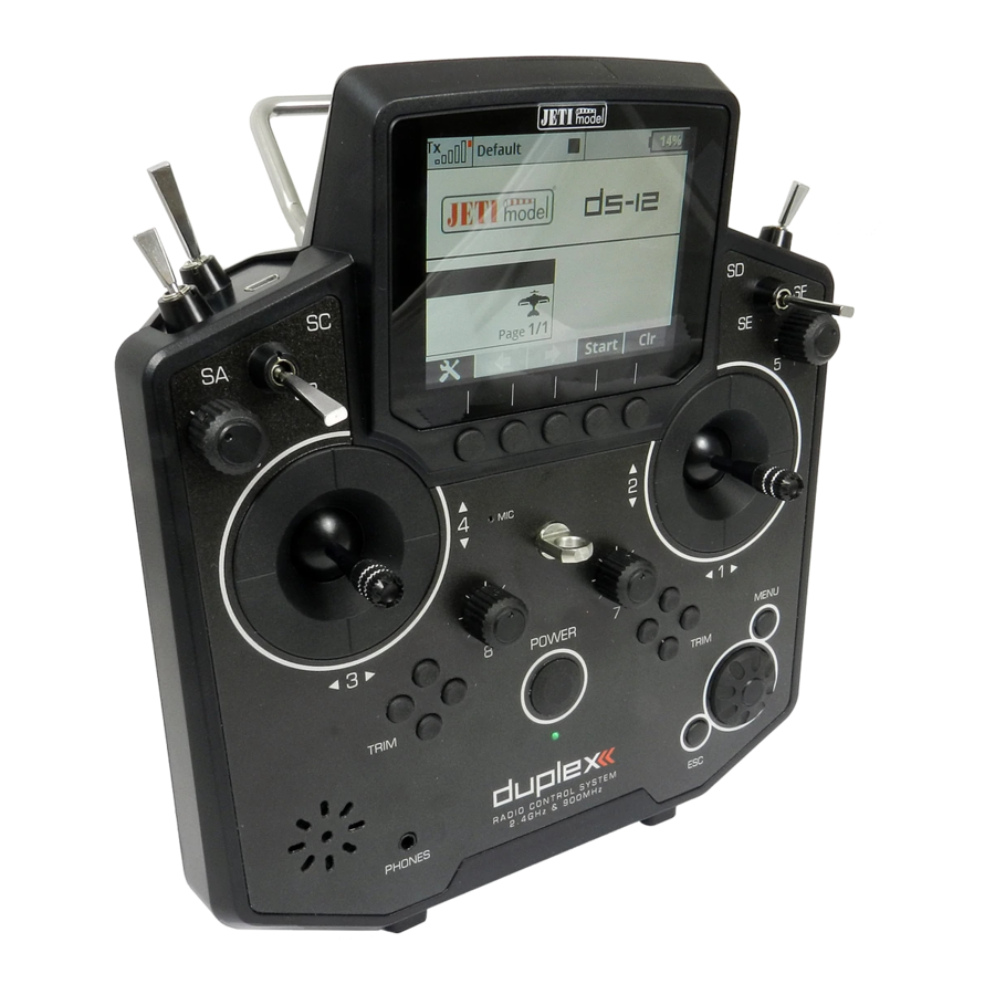
computer radio control system 4 Description of Transmitter DS-12 4.1 Control Identification DS-12 Right Stick 1, 2 – the DS-12 Transmitter Supports Modes 1-4, see Control Sticks -> mode change Left Stick 3, 4 the DS-12 Transmitter Supports Modes 1-4, see Control Sticks ->... -
Page 16: Assembly Identification
computer radio control system 4.2 Assembly Identification Battery Connector Micro SD Card Transmitter Battery Pack 2.4GHz Antennas PPM Output Connector 900 MHz Antenna Left Gimbal Assembly Right Gimbal Assembly... -
Page 17: Control Stick Assembly
computer radio control system If you have installed optional sticks with switch or 4.3 Control Stick Assembly Warning: button ends; make sure that while adjusting the stick length you observe the wires that pass through the Note: When handling with back cover removed always stick shaft and through the gimbal opening in order switch off the transmitter and disconnect the to prevent damaging the connecting cables. -
Page 18: Ratchet Tension Adjustment
computer radio control system Use indicated machine adjustment screws to change the For ratchet tension adjustment use the machine screw “A” desired spring tension. By turning the screw countercloc Turn slowly (counter-clockwise) until you achieve the desired kwise, you will loosen spring tension. As a result the moving ratchet tension. -
Page 19: Throttle Stick Travel Adjustment
computer radio control system 4.3.5 Throttle stick travel adjustment 4.3.6 Changing the transmitter mode The transmitter is equiped with universal multimode gimbals. Both The throttle stick travel is adjustable to suit your flying style. gimbals are identical and can be adjusted mechanically for modes 1- 5. - Page 20 computer radio control system B. Setting the multi-mode gimbal into the mode with locking the middle position - elevator Loosen the screw Slightly lift the lever Turn the lock in the direction of the arrow and arrest the lever in the upper position. Move the lever in the direction of the arrow to release the lever Tighten the screw Loosen the screws E and D in a position so that tension is removed...
-
Page 21: Swappable And Assignable Switches
computer radio control system 4.4.1 Switch Removal Procedure 4.4 Swappable and Assignable Switches Switch off the transmitter and remove the 7 screws that secure the radio back cover. Next, remove the radio back cover. One of the most important features of a JETI transmitter is the switch Be sure to disconnect the transmitter battery pack function assignment flexibility. -
Page 22: Assembly Procedure
computer radio control system Disconnect the flat flexible cable from its connector on the After you turn on the transmitter for the first time after any switches main board. have been modified, you will notice that the configuration for a selected model no longer matches. -
Page 23: Digital Trims
computer radio control system 4.6 Transmitter Battery Pack 4.5 Digital Trims Transmitter gimbals are used for controlling the basic flight The DS-12 transmitter is powered by a Li-Ion type battery pack and functions like throttle, roll(aileron), pitch(elevator), and yaw(rudder). comes equipped with its own built-in advanced battery Immediately under the transmitter gimbal sticks you can see four management and charging circuit. -
Page 24: Battery Replacement
computer radio control system 4.6.2 Battery Replacement 4.7 PPM Input/Output Connector Should you decide to replace the transmitter battery, please follow these steps: The PPM output is accessible via connector labeled "B“. This connector features the non-stabilized battery voltage output in the Switch off the transmitter and remove the 7 screws that range of 3.2V - 4.2V (max. -
Page 25: Handling
computer radio control system 4.8 Handling 4.9 Change SD Card The DS-12 is equipped with a handle for practical manipulation as Disconnect the battery plug . shown in the picture. To open the SD card holder, use a fingernail to push the metal frame to the right and then lift it carefully . -
Page 26: Rf Transmitter Modules
RF module. • „Student“mode – the 2.4GHz Duplex module is assigned to communicate with the instructor transmitter only. Communication with the model takes place via instructor’s transmitter only. If you operate two of the DS-12 transmitters, one of them in the "Instructor“... - Page 27 computer radio control system Recommended connection for Rsat900 NG as a backup receiver Connecting the RSat 900 NG directly to a Primary receiver : with a Central Box • The RSat900 receiver is plugged into the “Sat1” slot of the primary •...
-
Page 28: Transmitter Powering On/Off
computer radio control system 6 Transmitter Powering ON/OFF 6.2 Transmitter Turning-OFF The transmitter is switched-off by pressing the "Power“ main 6.1 Transmitter Powering-ON button. Before complete power-down is achieved you will be asked for additional confirmation. In case of an emergency, a fast turn-off Switching-on is achieved by pressing and holding the "Power“... -
Page 29: Initial Switching-On
computer radio control system 7 Initial switching-on 7.1 Main display Turn the transmitter on by pressing and holding the „Power“ button The main screen displays basic information about operation of your for a couple of seconds and then press the "F5 (Yes)" button to transmitter, such as the battery level, time, flight mode, etc. -
Page 30: Navigation In The Menu
computer radio control system The lower bar is found at the bottom of the main display. 7.2 Navigation in the Menu The lower bar shows: 7.2.1 Navigation The „menu“ button allows you to switch between the main display and the transmitter‘s main menu. Also, If you push this button while turning the 3D Control Advice: Selector to edit values, the values can be changed faster. -
Page 31: Browsing Through The Menu
computer radio control system 7.2.3 Basic Menu Structure * Model - Telemetry Controls - Select Model - Voice Commands - New Model - Sequencer - Accelerometer - Basic Properties - Model Image & Colors * Timers/Sensors - Functions Assignment - Timers - Servo Assignment - Alarms - Servo Setup... -
Page 32: Model Set-Up Guide
computer radio control system 7.3 Model Set-up Guide Warning: For safety reasons we recommend first removing the propeller. In this section we will guide you, step by step, through the process of Switch-on the transmitter. In the main creating a new model airplane and helicopter. Each step of the guide display push the key „menu“. - Page 33 computer radio control system Select your wing type. Because this The screen will now display a request which example has 2 aileron servos, select „Wing asks if you really want to create and activate type“ 0FLP/2WING. Do not change any the new model.
-
Page 34: Helicopter
computer radio control system From the main screen, push the „menu“ 7.3.2 Helicopter button. Select „Fine tuning“ and push the Let’s create a simple model helicopter. In this example, the „3D button“. helicopter is controlled by a swash plate with three servos at 120° orientation and the motor has no governor. - Page 35 computer radio control system Select the helicopter swash plate type"3 Switch on the transmitter. In the main servos (def 120°)“. Change the second display push the key "menu“. Select the menu item "Position of front servo“ to item "Model“ and push the "3D button“. "Rear“...
-
Page 36: Multicopter
computer radio control system In the "Fine tuning -> Flight modes“ menu you will setup these The "Swash Mix“ menu displays the travel advanced model control functions for your helicopter: range of each particular helicopter flight function for the swash plate for flybarred Collective pitch curve, see: Fine tuning ->... - Page 37 computer radio control system Servo assignment to receiver channels: Select the item „New model“ and push Throttle the „3D button“. Roll (ailerons) Pitch (elevator) Yaw (rudder) Mode (multicopter mode channel) Enter the name of your model and press Before you begin creating a model, make sure that you have setup „F5(OK)“...
-
Page 38: General
computer radio control system This page displays the flight control Bind transmitter with the receiver, see chapter 8.3 Receiver- functions and their transmitter switch >Binding. Once your transmitter has been bound with the receiver assignments. Here you can verify that your and you have re-applied power to the receiver, the last setup phase is flight control functions are correctly the tuning of your flight controller channels, see chapter 7.3.5... - Page 39 computer radio control system Before creating a model, make sure that you have setup the correct Choose an optional model image and transmitter mode in "Main menu -> System -> Configuration -> color profile according to your personal MODE 1-4“. The basic, standardized, assignment of transmitter preferences.
- Page 40 computer radio control system (spring-loaded switch). After you create all of your desired functions, Once your transmitter has been bound with a receiver and has been press the „F5(Next)“ button to confirm. connected to its power supply, the last step consists of tuning the servo output functions, see chapter 7.3.5: Setup of receiver The "Servo assignment“...
-
Page 41: Setup Of Receiver Outputs
computer radio control system 7.3.5 setup of Receiver Outputs their full travel. You should use the dual rate function to set your model’s useable control throws. Go to the "Model->Servo Setup“ menu. Use the "F2“ and "F3“ buttons to brows through the receiver outputs (channels). You can scrol through the following servo adjustment items for each channel: „Servo reversing“... -
Page 42: Duplex Receivers
The binding process needs only to be done once SAT - auxillary input/output for PPM signals. This input allows for each receiver. you to connect an additional JETI DUPLEX Rsat2 satellite receiver or an additional US version Duplex receiver.This allows you to increase 8.3.1 Standard pairing procedure the number of receiver antennas in your system for increased Switch off the transmitter and receiver. -
Page 43: Alternative Pairing Procedure Through The Transmitter Menu
JETI authorized service centers. 8.5 Fail safe All Duplex 2.4GHz system receivers are equipped with "fail safe“, a function which reacts to control signal transmission interruptions. When your receiver for any reason does not receive transmitter information, it changes, after a pre-set time period, to one of the following modes. - Page 44 computer radio control system Each receiver channel can be configured to one of the modes described above. We recommend that you setup "fail safe“ positions for every output, which enables your model to stay in a stable condition. For instance, the elevator and rudder in neutral positions, electric motor switched-off, gas engine idling, spoilers extended.
-
Page 45: Using Device Explorer To Configure The Receiver
computer radio control system In the picture above, two receivers have been detected and are Using Device Explorer To Configure the Receiver recognized. When you press the rotary button, you are able to configure them in detail. Here is the example how to use the Device The Device Explorer utilizes the latest Explorer to configure an "R9 EX"receiver: data/command EX Bus protocol to... - Page 46 computer radio control system - Reset to factory defaults... – After confirmation, the receiver's Note: Before a device can be recognized, a special predefined configuration will be restored to its factory settings. configuration scheme must be present on the SD card in the /Devices folder.
- Page 47 computer radio control system - PPM/UDI Mode - determines processing and additional logic moment of losing signal until the fail-safe is activated. This option is applied to the PPM and UDI protocols. available only if the Individual mode is selected. - Direct - signals received from the transmitter are not further on - Each output position of the receiver has three adjustable processed in the receiver, they are generated without any change at...
-
Page 48: Support Of Remote Commands For Ex Bus Devices
computer radio control system The page Receiver Outputs (picture )) allows you to redirect your The screen , "Alternative Pin Config", allows you to modify the transmitter’s channels to any output of the receiver. For convenience modes of receiver output pins. The servo outputs can be configured the transmitter’s channel numbers are displayed together with the into Digital input and Digital output modes. - Page 49 computer radio control system On the main screen of the Central Box settings scroll down to display The list of active commands. the maximum telemetry values (Telemetry Min/Max). Here you will find a choice to assign a switch to the command for deleting measured minimums and maximums (Clear Min/Max switch).
-
Page 50: Rc-Switch
computer radio control system Variant of the RC Switch Note: This text describes receiver properties introduced in DS- Power In 12 V3.0 and receivers version 3.25. Earlier versions of the Power Out firmware might offer different properties, or the Receiver battery RC Switch RC Power Switch described configuration might be entirely inaccessible. - Page 51 computer radio control system...
-
Page 52: Main Menu
computer radio control system 9 Main menu The numbers on the left side of the display shows the sequence You reach the basic menu from the main display by pressing the of the menu items. „menu“ key. The main menu is divided into a basic and a user section. In the basic menu, the menu items are divided into sub-menus. -
Page 53: Pa S S Wo Rd P Ro Te C T I O N A G A I N S T A Cc I D E Nt A L
computer radio control system 9.0.1 Pa s s wo rd p ro te c t i o n a g a i n s t a cc i d e nt a l calibration of controls logging telemetry configuration changes USB connection If you lend the transmitter to another person and you want to ensure switching off... -
Page 54: Model
computer radio control system "Model checking“ function, which compares the series number of 9.1 Model the receiver in the model profile with the series number of the receiver with which it is starting to communicate. If the two series The „Model“ menu contains basic functions for working with your numbers do not match, the transmitter displays a warning that a model, like: different receiver has been detected for the model. -
Page 55: New Model
computer radio control system Choice of model sequence Copying a model The sequence of models can be changed by using the "F1“ button to The complete setup information of a model can be copied and used move the selected model one position downwards or by using the to create a new model with the same programming. -
Page 56: Basic Configuration- Airplane
computer radio control system efficient by populating the menus with many of the popular options for each type of model. The possible choices are: Aero, Heli, X-Copter and General. Once your model is stored it is not possible to change that model’s type. -
Page 57: Basic Configuration - Helicopter
computer radio control system Number of Landing Gear Servos in the model Type Description You can select up to 4 landing gear servos. You can then assign the 0FLAP.|1AIL Only one aileron servo control of each landing gear servo to a different receiver channel if 0FLAP.|2AIL Two aileron servos needed. - Page 58 computer radio control system Swash Plate Type Swash plate angle Enter the type of swash plate your helicopter is using. Refer to your The "Angle“ item is only accessible in the "3 servos (default 120°)“ helicopter’s manual if necessary. swash plate type. The angle formed by swash plate points 1 - 2 and 1 –...
-
Page 59: Swash Mix
computer radio control system Editing an item "Value" affects the diameter of the displayed circle, Note: If you activate the additional function of the gyro in the ie. size of the maximum allowed deflection. The setting is global for active model, after leaving the Basic Properties menu it the whole model. -
Page 60: Basic Configuration-General
computer radio control system 9.1.7 Basic Configuration-GENERAL Model / Wallpapers You can display two types of model images. A smaller model image and a larger model image on all screens where the telemetry values are displayed (Menu - Timers / S e n s o rs - telemetry display). Background image. - Page 61 computer radio control system of these items, you will enter the menu: "Select control input“, see chapter 9.7. The assignments can easily be verified by the graphic found beside the control element description in the " Trim “ section, which shows the actual setup of the assigned control element. The trim functions for the gimbal sticks P1-P4 are automatically assigned to the quad push-buttons located below the gimbals.
-
Page 62: Servo Servo Assignment
computer radio control system Assignment of Transmitter Output Functions to Receiver Note: The initial assignment is carried out in accordance with your selected transmitter mode. If the initial assignment is incorrect, Channels check the transmitter mode setup in the "Main menu->System- Select the required receiver channel and press the "3D button“. -
Page 63: Servo Setup
computer radio control system 9.1.11 Servo Setup This menu is for the additional tuning of output functions of the Center (Subtrim)With this item you can adjust the servo transmitter->receiver channels->servos. The assignment of a neutral position of the selected receiver channel. transmitter output function to a receiver channel is shown in the Advice: When building a model try to mechanically adjust the... -
Page 64: Servo Balancer
computer radio control system Servo Reversing point is located in -25%. It is then possible to move the point upwards or downwards by turning the „3D button” to the right, or Use this item to reverse the direction of a servo’s travel. respectively to the left. - Page 65 computer radio control system Advice: If you use several mechanically Setting the display of the Note: linked servos to control a single telemetry data on the top wing surface in the model as menu bar of the screen is saved shown in this example, we a s a p a r t o f t h e m o d e l recommend setting all the...
-
Page 66: Fine Tuning
computer radio control system Up to 10 different flight modes (depends on activated transmitter 9.2. Fine Tuning 9.2 Fine Tuning equipment) are available for every single model. Each one of these - Extended program functions for fine tuning your models flight modes can be named differently for instant recognition. - Page 67 computer radio control system Flight Mode Delays Advice: If no flight mode is required, do not change the pre-set configuration. The time delay function can help smooth the transition from one flight control state to another. Sudden changes in the positions of your control surfaces can negatively affect performance or even create a critical situation.
- Page 68 computer radio control system Deleting a Flight Mode Name of the To delete a flight mode: current flight mode. Highlight the desired flight mode and press the “F4 (Opt.)” button to see the options menu. Scroll and select the “Delete flight mode” option and press the “F5 (OK)”...
-
Page 69: Digital Trim
computer radio control system transmitter does not remember the value of trim after shutdown. 9.2.2 Digital trim After loading the model, the trim value is always 0%. In combination Fully programmable digital trims are located right under the with the logical switches this option is suitable for a sequential transmitter gimbals as a set of four directional buttons. - Page 70 computer radio control system Centered mode – by default, the trim affects only the servo • Advice: For the maiden flight we recommend using larger trim center, the endpoints remain untouched. steps. After familiarizing yourself with your model’s • Linear – shifts the whole servo travel, including endpoints. behavior you can switch to smaller steps for finer trimming.
-
Page 71: Flight Mode Trims
computer radio control system Warning: The Autotrim feature, when active, always influences the High Endpoint model functions currently assigned to the particular trim buttons (except for throttle function which is never affected by Center Center Center Center Center this feature). The Autotrim function does not take effect on the auxiliary incremental trims. -
Page 72: Dual Rate/Exponential
computer radio control system Trim Travel Global or Separate Setting Channel name The servo trim position for each function output can be set either Dual/Triple rate travel setting collectively for all flight modes by selecting the “G-(global)” or Exponential setting individually for each separate flight mode by selecting “S- Global or separate flight mode setting (Separate)”. - Page 73 computer radio control system Expo Global or Separate Setting higher number increases travel, a lower number decreases travel. Expo configuration for all channels can be set collectively for all Expo rate is defined by percentage of the function curve . Zero rate represents linear function.
-
Page 74: Programmable Function Curves
computer radio control system 9.2.5 Programmable Function Curves (*depends on equipment) • If V-Tail is selected, the option influences both rudder and elevator. Function curves define the relationship between the actual position of your stick/switch/knob and the position of the servo. This screen •... - Page 75 computer radio control system By pressing the “3D Control” button you can switch between the Standard Linear values, set In/Out point individual curve points. Pressing the “Esc” function will return you Constant Constant value, set point to the previous control point. On the left side of the graphic interface 3-Point, x>0, 3-Point curve, set value for 3 points you will see the percentage representation of your selected control...
-
Page 76: Aileron Differential
computer radio control system The travel range for each servo can be set. Scroll and highlight either Using the SMOOTH function, you can completely smooth out your the “Up” or “Down” menu line with “3D Control” button. Press the curve between the selected points. "3D Control“... -
Page 77: V-Tail Mix
computer radio control system 9.2.8 V-Tail Mix If your model is equipped with a V-Tail, The two basic tail functions (rudder and elevator) are mixed to control the tail of the airplane. The V-Tail mix has to be activated by choosing the “V-Tail 2H” tail setting. Unless you have previously chosen a different percentage for one of the tail mixes, the initial settings for “V-Tail”... -
Page 78: Delta/Elevon Mix
computer radio control system 9.2.9 Delta/Elevon Mix each servo. If the servos need to be adjusted independantly, use the “F1 (Sym.)” button to unlock the servo travel for adjusting the The Delta/Elevon Mix uses two servos for the control of both the individual values in the selected menu line. - Page 79 computer radio control system movement of the control surfaces during the change. Increasing the differential. Positive values increase the upper travel of the aileron number on the positive side “+” slows the deployment while servos, negative values increase the lower travel of the aileron increasing the number on the negative side “-”...
-
Page 80: Free Mixes
computer radio control system appropriate butterfly travels. The way these values influence servo Copying a Free Mix deflections depends on the position of the butterfly's control stick Highlight an existing free mix and use the “F1 (Copy)” button to and the position of the butterfly's Tuning control. create a copy of the existing mix. - Page 81 computer radio control system Free Mix Deployment Delay The time delay function can help smooth the transition from one state to another. Values adjusted in the “Source” item will slow down full mix deployment when the mix is ON (switched ON or always ON) and the master channel changes its value.
- Page 82 computer radio control system be influenced by the aileron differential settings. If this option is (Slave). Here is how to create a free mix whose input is controlled by an existing free mixer output: deactivated, the output of the mix is transmitted directly to the servo without any modifications.
-
Page 83: Governor/Gyro
computer radio control system 9.2.12 Governor/Gyro In the Gyro settings menu it is possible to edit up to three main values for each gyro function in all flight modes separately according Typically, a gyro is used to stablize a model helicopter along its to the position of the main control/switch. -
Page 84: Throttle Limiter
computer radio control system have three different settings (Position 1, Position 2, Position 3) for the governor sensitivity. You can always assign this function to a different transmitter control element (knob, slider, switch) in the „Model, >Function Assignment“ menu. The governor settings can be set collectively for all flight modes by selecting the “G-(globe)”... -
Page 85: Advanced Properties
computer radio control system 9.3 Advanced Properties Advanced programming menu for DS-12. Separate switches for ever y direction. The priority goes from up/right direction (highest) and continues until down/left (lowest). Master mode – the stunt itself is done by activating a master switch (Sa in this case). -
Page 86: Sticks / Switches Setup
computer radio control system Auto-Trim Function Throttle Cut Setting (*depends on equipment) Auto-Trim function can be activated using any assigned switch, This safety feature is mainly for models using glow or gasoline knob or stick. Once this function has been activated you can trim engines as their main source of power. - Page 87 computer radio control system Switch & Stick Type A function in this range (middle) can be considered to be either The first menu line item lists the control’s number and the second “Switch ON” or “Switch OFF” item lists the type of control element. Using the “F2” and “F3” A Function below this point is considered to be“Switch OFF”...
-
Page 88: Wireless Modes/Trainer
computer radio control system 9.3.3 Wireless Modes/Trainer The transmitter RF module can operate in one of three modes. For a detailed explanation. (see section 5) The wireless RF setting is programmed to the memory of individual models (receivers). While programming a selected model you will need to configure the RF module settings. - Page 89 computer radio control system “Instructor” Mode Assignment for the input channel from the student’s transmitter to the Control function of the instructor’s transmitter. The Trainer Mode allows you to directly assign an arbitrary control (switch, stick, even a logical switch) which will be emulated for further use in the student's or teacher's transmitter.
- Page 90 Trainer Mode for JETI DS-12 as the Instructor Radio Other brands of transmitters can be used by the student with a JETI Duplex EX 2.4GHz radio system by using a PPM cable for communication with DS-12 transmitter. Make sure that the instructor’s transmitter is bound to the aircraft in the “Default”...
- Page 91 computer radio control system Pairing the transmitter with receivers in Double Path mode Signal Loss Alarm Settings It is possible to define a specific response from the transmitter after Make sure that receivers are set in Normal mode, not in Clone one or more receivers disconnect or lose signal.
- Page 92 Backup. You can bind the 900MHz NG receiver in the same way as turns Off automatically when the USB connection is activated. standard Duplex receivers. Caution: If you disable the transmission with a model attached, Insert bind plug to the 900MHz NG receiver you may cause a signal loss alarm.
-
Page 93: Logical Switches
computer radio control system 9.3.4 Logical Switches (*depends on equipment) If you want to have single or multiple transmitter functions which are controlled based upon the condition of other control conditions, then setting up a logical switch is the way to go. Each logical switch is defined by a logical expression. - Page 94 computer radio control system Emulating a 3-Position Switch • The AND condition: The resulting value of the switch is You can use the logic function “Multi” to allow the logic switch to act calculated as minimum value from both controls. If you have two as a 3-position switch.
-
Page 95: Sounds On Event (Sound Assignments)
computer radio control system 9.3.5 Sounds on Event (Sound Assignments) You can combine more controls using logical conditions: You can assign an audio file to be played based on any transmitter condition. This means that any music file stored in the transmitter can be assigned to any switch, stick, knob, logical switch, alarm or any other special function. -
Page 96: Sequencer
computer radio control system To add control points, you should move the timeline (edit Sound Repeat “Time” column) so that it reaches the desired time. Then press the This menu item allows you to repeatedly play any sound after it has "F3 Add”... -
Page 97: Accelerometer
computer radio control system Within this menu, you can edit • Cycling – if you wish a cyclic behaviour for your beacons, following parameters: turrets or radar assemblies just check this option. Filtering – This increases • Always finish sequence – After checking this option, the smoothness of the movement for sequencer will never be interrupted and always will travel from the each axis separately. -
Page 98: Telemetry Controls
computer radio control system 9.3.8 Telemetry Controls (*depends on equipment) After you have finished setting the inertial unit itself, you can assign the resulting variables to any function using a standard input dialog Not only can you display telemetry data, record it to your SD card or (picture ). -
Page 99: Sound Of Proportional Controls
computer radio control system Examples for the possible use of telemetry controls Duration – Minimum time of being switched on. If an event takes a very short time, it is possible to extend the time of the telemetry • If the model speed is less than X m/s, flaps will be raised control being switched on for the time specified by this parameter. -
Page 100: Voice Commands
computer radio control system You can create up to 15 different voice commands (plus a keyphrase) control position (Center-Beep mode), but voice announcements of that are shared between all models. For each model separately it is the current position is also available (Voice mode). possible to specify which commands are active. - Page 101 computer radio control system Voice recognition modes learning process. Push-To-Talk mode – Locate the Voice Commands menu, choose the Keyword mode. The voice command must be Open the Keyword settings dialogue. Here assign the Push-To- pronounced while the Push- To-Talk Talk switch.
- Page 102 computer radio control system By pressing the "F2" Graph button you can view the sound frequency analysis which is helpful in case you need to find possible sources of noise that degrade the sound quality. The "F3” Delete button clears the highlighted voice command so you will need to train it again before use.
-
Page 103: Timers/Sensors
computer radio control system Model Time/Reset Timers at Power Up 9.4 Timers/Sensors By pressing the "F1" button you can choose which timers will be - Set up of Timers and Telemetry Sensors reset after turning on the TX or after selecting the model. By default, all timers with specified Short Reset option are cleared. - Page 104 computer radio control system Editing a New Timer switch is triggered. Once started, this type of timer can only be Timer Name stopped using the "F4(Stop)“ button. When you add or change the timer name, the name is automatically Use the „F5(Clr)“ button from the desktop to reset the timers. displayed in that timer’s box on the main desktop.
-
Page 105: Alarms
EX Alarms Duplex EX sensors generate their alarms directly to the transmitter. The corresponding Duplex EX sensor must first be connected to a Duplex EX receiver and the receiver must be bound to the transmitter. It may take several minutes for the transmitter to initially communicate the sensors. - Page 106 computer radio control system Creating an Alarm Set Throttle Idle Use the „F2(Add)“ button to add an alarm. Then, in the „Sensor“ With this item activated, you model’s throttle will go to idle when the item, select the sensor whose alarm limit you want to set. alarm condition occurrs.
-
Page 107: Vario
computer radio control system • Range (minimum, center and maximum). Here you can define 9.4.3 Vario (*depends on equipment) the full range of the sensor which will be indicated by the Vario Located in: „Menu->Timers/Sensors/Vario”. There are two types of system. - Page 108 computer radio control system allows you to determine whether you want to hear the time of a way to add a variable to the Repeat queue or to remove a variable current lap which is already running or hear the time of the previous from the Repeat queue.
-
Page 109: Sensors/Logging Setup
9.4.5 Sensors/Logging Setup data is a part of the standard telemetry record and can be displayed This menu lists all of the Duplex EX sensors and their values which as the other parameters. are operating in your model. When you connect a sensor to a Duplex... -
Page 110: Displayed Telemetry
computer radio control system 9.4.6 Displayed Telemetry Distance: Metres (m), kilometres (km), feet (ft.), yards (yd.), miles (mi.). This menu lists all of the user information blocks which are displayed on the desktop. You can use this menu to manually add, delete, Speed: rename and resize the user information blocks displayed on the Metres per second (m/s), kilometres per hour (km/h), feet per second... - Page 111 computer radio control system „User Name“ - User name. „Tx Battery“ - Transmitter Battery Status • Charge/Discharge current rate „JETIbox“ - JETIBOX emulation screen Press the ESC button to see and • Actual Tx battery voltage operate standard JETIbox controls. •...
- Page 112 computer radio control system „Telemetry“ - Displays selected, connected telemetry sensor The user blocks can be either standard or double size. Double sized information. blocks obviously use up more of the desktop. In return, some of them display more data while others display the same data in a larger font.
-
Page 113: Main Screen
computer radio control system How the User Blocks are Displayed Telemetry displayed at clock panel The right end of the first line in the "Displayed Telemetry“ menu Here is where you can select one telemetry parameter, which will appear at location of the digital clock on the top bar of the screen. displays a symbol to indicate if the list of user blocks is displayed for all flight modes or just the current flight mode. -
Page 114: Applications
computer radio control system to find the latest record. After the 9.5 Applications a p p ro p r i a te f i l e h a s b e e n selected, you will be redirected back to the screen a). There you can select up to three variables that will be displayed in the graph. -
Page 115: Audio Player
computer radio control system • "F5" 1/2/3 button toggles between the variables that have been selected on the screen Audio files are supported in *.mp3 and *.wav format. Pilot Voice Caller Note: You cannot display a log file which is currently being written to. To The Audio Player application offers a possibility to play audio files view the most recent file, you should stop logging and clear the sequentially. -
Page 116: Jetibox
Check the “Continue playback” option if you wish the transmitter to continue playback through the whole folder. 9.5.3 JETIBOX For maximum compatibility with 1st generation JETI DUPLEX, the DS-12 are equipped with a JETIBOX emulation function. This emulation shows its information in the legacy two-line display format. -
Page 117: User Applications
The "F2” Refresh button reloads all user applications and restarts the Lua session. For further information about the Lua application programming please refer to “JETI DS-12-24 Lua Programming API” document that can be downloaded at www.jetimodel.com. -
Page 118: System
computer radio control system 9.6.1 Configuration 9.6 System Basic transmitter settings - Use this menu to configure the system functions of your transmitter. All of the settings in this menu are global and do not change when you switch between models. Language Setting Use this menu to select the transmitter’s language setting. - Page 119 computer radio control system User Name Transmit frequency Enter the user name that you want to appear in the User block on the Says how often the stick positions will be refreshed. Please check the desktop. settings of your receivers prior setting this option to 100Hz. The Stick Mode Output Period should be set to "Auto"...
- Page 120 computer radio control system PPM Output Connector): - Off – the connector output (pin No. 4) will not generate any kind of Check Signal Before Flight signal. It is possible to check the signal strength immediately after the - PPM Positive – the connector output (pin No. 4) will generate model is turned on and connected to the transmitter.
-
Page 121: Servo & Range Test
computer radio control system Starting the Servo Test 9.6.2 Servo & Range Test Press the “F3 (Start)” button to start the test for your selected servo This menu allows you to perform a range test and servo tests. outputs. During the servo test it is possible to send the test output to all of the Once started, the servo test will continue to run even if you exit the channels which are active in the current model setup. -
Page 122: Receiver Output (Servo Monitor)
If you have modified the "Channel Set“ or "Pin-Out Setting“ of your Duplex receiver then the displayed receiver output channel numbers may not be accurate. If, however, your Duplex receiver still has its default channel settings then this list will Proportional Input Display be accurate. -
Page 123: System Sound
computer radio control system -Low TX Voltage - Optional file with a warning at low transmitter voltage. You can also set an adjustable voltage level which says when the alarm will be activated. -Low Signal - An optional file with a warning at low signal level. The file is played when the signal level of both antennas falls below a number specified in the parameter "Value". -
Page 124: Installed Modules
computer radio control system • Playback Volume – volume of played WAV files (Alarms, Audio 9.6.8 Limitations In Copying Models Between Transmitters Player and Sound on Event). When copying models from one transmitter to another one, it is • necessary to bear in mind that the transmitters may not have the Stop Playback Switch –... -
Page 125: Info
computer radio control system Note: Leaving the menu disables the connection. 9.6.10 Info This menu displays information about your DS-12-24 such as: product name, firmware version, available memory, etc. Press the "F5 (Ok)“ button to exit this menu. -
Page 126: Throttle Lock
computer radio control system 9.7 Throttle Lock 9.8 Select Input control Throttle lock is an important safety feature incorporated in your DS- This menu allows you to select your desired input control device 12-24 transmitter. This feature effectively "locks" the throttle (switch, knob, stick or logical switch) for a given function. - Page 127 computer radio control system Reversing Switch Assignment Press the „F3 (Rev)“ button to change the control device activation When the menu appears, you can either press the "F1 (Log)“ button direction. to select/edit a logical switch for your function or you can simply This will not reverse the output direction of your function.
- Page 128 computer radio control system signal should be present on the pin No. 1. To prevent any damage, transmitter is shifted to the left, or respectively to you need to use the 3V logic level and protective elements on the the right (not available for DC). input.Throughout the model settings you can assign any of the PPM •...
- Page 129 computer radio control system Preview of the individual screens of the dialogue for selecting control input...
-
Page 130: Trim Menu
computer radio control system 9.9 Trim Menu 9.10 How Transmitter Output Functions are Processed This menu displays the current trim settings. You can access this menu from the desktop by either pushing the "3D control“ or by This chart displays how the transmitter Control Device simply pushing one of the trim buttons. -
Page 131: Transmitter To Pc Connection
10 Transmitter to PC Connection 10.2 Update firmware The JETI Duplex line of transmitters are equipped with a mini USB The JETI Duplex line of transmitters fully support future software port. The Transmitters also come with a standard USB to mini USB updates. -
Page 132: System Backup
computer radio control system 10.4 System Backup 10.7 Copying models between the transmitters Data backup is as easy as the standard backup you can perform on Configuration of all models in the transmitter are stored on the your PC. You can save all your data onto a PC hard drive or CD. The internal SD card in the directory /Model/. -
Page 133: Battery Safety Handling Rules
computer radio control system 11 Battery Safety Handling Rules 11.2 General Safety Rules 11.1 Transmitter Battery Pack Any repair, installation, or upgrade must be performed with caution and common sense. These will The Installed battery pack must be charged from an AC voltage require some basic mechanical skills. -
Page 134: Flight Safety Check
computer radio control system Do not point the transmitter antenna directly towards your direction of movement for your flight surfaces. model or a human body. The radiation pattern from the antenna will Set motor/engine kill switch and test the power train. be shielded and provide poor connection to your model. - Page 135 computer radio control system radioélectrique à l'intention des autres utilisateurs, il faut choisir le THIS DEVICE COMPLIES WITH PART 15 OF THE FCC RULES. type d'antenne et son gain de sorte que la puissance OPERATION IS SUBJECT TO THE FOLLOWING TWO CONDITIONS(1) isotroperayonnée équivalente (p.i.r.e.) ne dépasse pas l'intensité...
-
Page 136: Model Menu - Airplane/Sailplane
computer radio control system 12 Model Menu – Airplane/Sailplane 12.2 Aileron Differential Aileron Differential is available with wing configurations of 2 ailerons 12.1 Butterfly Mix (Crow Mix) servos or more. You can find the Aileron Differential menu in “Fine Tuning, >Aileron Butterfly/Crow mixing is available with wing configurations of 2 Differential”. -
Page 137: Ailevator
computer radio control system 12.3 Ailevator 12.4 V-Tail Mix The ailevator function uses two servos for the elevator channel. Both The V-Tail mix function uses two tail servos to control both the sides can be programmed to be controlled independently. elevator function and the rudder function. -
Page 138: Delta/Elevon Mix
computer radio control system 12.5 Delta/Elevon Mix 12.6 Spoilers to Elevator Mix The Delta/Elevon Mix uses two servos for the control of both the For models equipped with spoilers, the elevator is often used to elevator and aileron functions. This mix is most commonly used for compensate for any pitching tendencies generated when the Delta type aircraft. -
Page 139: Ailerons To Rudder Mix
computer radio control system When you press the “F4 (Curve)” button 12.7 Ailerons to Rudder Mix you go directly to curve function menu One of the most commonly used mixes for sailplanes, this mix screen. function will allow you to mix rudder function with your ailerons to help your model have more coordinated turns. -
Page 140: Rudder To Ailerons Mix
computer radio control system 12.8 Rudder to Ailerons Mix One of the most commonly used mixes for 3D planes, this mix helps to improve your control in knife-edge flight and while performing other 3D aerobatics. You can use one of the free mixers to set up this mixing function. -
Page 141: Butterfly (Crow) Mix
computer radio control system 12.9 Butterfly (Crow) Mix To edit the mix simply highlight the mix and press the “F4 (Edit)” button to go into The basic configuration of the butterfly mix (also known as crow) is the selected mix’s advanced menu. created by using ailerons, flaps, and elevator flying surfaces. -
Page 142: Rudder To Elevator Mix
computer radio control system 12.10 Rudder to Elevator Mix To edit the mix simply highlight the mix and press the “F4 (Edit)” button to go into Another one of the most commonly used mixes for 3D planes, this the selected mix’s advanced menu. mix helps to improve your control in knife-edge flight particularly to help with any coupling issues. -
Page 143: Aileron To Flap Mix
computer radio control system 12.11 Aileron to Flap Mix To edit the mix simply highlight the mix and press the “F4 (Edit)” button to go into This is also one of the more commonly used mixes for sailplanes. the selected mix’s advanced menu. Mixing flaps with your ailerons will increase you model’s aileron response. -
Page 144: Aileron To Flap Mix (Brake Variation)
computer radio control system 12.12 Aileron to Flap Mix (Brake Variation) 12.13 Elevator to Flap Mix This mix variation is used if your model is equipped with 4 flaps and If your model is equipped with flaps you might want consider mixing you want only the inner flaps (the set closest to the fuselage) to move the flaps to the elevator. -
Page 145: Flaps Mix - Camber Control
computer radio control system To edit the mix simply highlight the mix 12.14 Flaps Mix – Camber Control and press the “F4 (Edit)” button to go into This is another popular sailplane mix. This mix allows you to the selected mix’s advanced menu. effectively change the airfoil of your model‘s wing by combining the flaps and ailerons to lower the trailing edge (under camber) of the wing. -
Page 146: Throttle Cut (Kill Switch)
computer radio control system 12.15 Throttle Cut (Kill Switch) 12.16 Throttle Idle This safety feature is mainly for models using glow or gasoline This feature is used to set the idle position for your throttle and will engines as their main source of power. Electric models can also prevent your engine from shutting-off when you move throttle stick highly benefit from this safety feature. - Page 147 computer radio control system...
- Page 148 computer radio control system...
- Page 149 computer radio control system...
- Page 150 computer radio control system...
- Page 151 computer radio control system ® JETI model s.r.o. Lomená 1530, 742 58 Příbor www.jetimodel.com...
Need help?
Do you have a question about the Jeti DS-12 and is the answer not in the manual?
Questions and answers
Especificaciones de bateria para radio Jety DS 12