
Summary of Contents for UNAOHM AP 01 HD
- Page 1 UNAOHM S.r.l. - Via G. di Vittorio 49 - 20068 Peschiera Borromeo (MI) Italy Tel. +39.02.36577787 - Fax +39.02.51650195 - Web : www.unaohm.it - E-mail : sales@unaohm.it ...
-
Page 2: Table Of Contents
INDEX SAFETY PRECAUTIONS AND GENERAL WARNINGS ..........4 1.1. SAFETY PRECAUTIONS .................. 4 1.2. GENERAL WARNINGS ..................5 1.3. MAINTENANCE ....................5 1.4. NOTES ......................6 INTRODUCTION ....................7 ... - Page 3 4.9.2.2. BANDWIDTH ................... 27 4.9.2.3. DEEMPHASIS .................. 27 4.10. SPECTRUM ANALYZER ................. 27 4.10.1. USE OF MARKERS ................27 4.10.2. SPECT ENGAGED MENU ................ 28 4.10.2.1. SPECTRUM GRID ................28 ...
- Page 4 7.4.6. AER (Adaptive Equalizer Response) in QAM ..........41 7.4.7. Technical specifications ................. 42 CONSTELLATION .................... 43 8.1. Use of constellation ..................43 MPEG4/MPEG2 DECODER ................45 9.1. Introduction ....................45 ...
-
Page 5: Safety Precautions And General Warnings
UNAOHM S.r.l. assumes no responsibility for incorrect use of the instrument or in case the specified rules are not complied with. -
Page 6: General Warnings
1.2. GENERAL WARNINGS • The liquid of the monitor is harmful. If the module breaks and the liquid eventually comes out, do not touch with your hands or any part of your body, especially eyes and mouth. In any case, wash immediately with water and soap. •... -
Page 7: Notes
This symbol indicates parts of the circuits with eventual dangerous voltage. UNAOHM S.r.l. reserves the right to bring modifications to this product at any moment and without notice, regardless of whether the change is of technical or commercial nature or being implemented to comply with legal requirements of specific countries. -
Page 8: Introduction
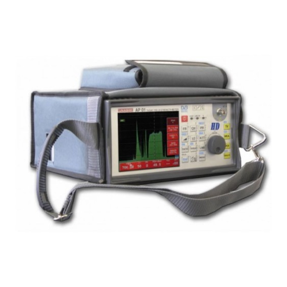
2. INTRODUCTION The AP01-HD field strength meter offers a full range of terrestrial TV, cable TV (CATV), the IF satellite bands and, as an option, the return path 5÷65 MHz. Its outstanding features are: • Broad dynamics of measurable level: from 20 to 130 dBµV in terrestrial, CATV and SAT ranges, from 40 to 130 dBµV in HF range (5÷65 MHz). -
Page 9: Technical Specifications
2.1. TECHNICAL SPECIFICATIONS Input VHF/UHF/SAT from 20 to 130 dBµV (-90 ÷ +20 dBm) Level from 40 to 130 dBµV (-70 ÷ +20 dBm) Measurement unit dBµV, dBmV, dBm e V, dB (for ratio measurement) (Selectable manual or automatic insertion) Attenuator HF/VHF/UHF/SAT from 0 to 60 dB in seven 10 dB steps Attenuator accuracy... - Page 10 Frequency Frequency range VHF/UHF/SAT from 45 to 2150 MHz (2); HF from 5 to 65 MHz PLL frequency synthesis with direct setting of frequency, channel or stored program through keypad and/or shaft Tuning encoder Possibility of selecting the channelization in force in the country where the instrument is used Storage capability 200 programs...
- Page 11 Monitor Picture area 5.7 ” (Diagonal) Resolution 320 (L) x 240 (A) pixels Contrast 300:1 Brightness 400 cd/m Pretreatment Anti-Reflection and Hard-coating (>2H) Visual angle ±55 ° (L), -30/+60 ° (A) Rear light Reception standard All with colour coding PAL - SECAM - NTSC. The following may be displayed on the screen: 1°...
-
Page 12: Standard Accessories
Data Logger Storage capability 5 plans of 50 programs each, 1500 acquisitions Power supply from 90 to 260 V 50/60 Hz Power 50 W Through 1 Li-Ion battery (standard) 16 V / 4.5 Ah Internal Vdc Autonomy approx. 4 hr (depending on performed services) Built-in, automatic. - Page 13 Picture 1 Front – control panel AP01 HD rev.09 UK...
- Page 14 Picture 2 Right side Picture 3 Left side AP01-HD_rev.09_UK...
-
Page 15: Controls, Connections And Indicators
3. CONTROLS, CONNECTIONS AND INDICATORS Front panel: 1. Bargraph for level measure 2. Shaft-encoder (to be turned to make adjustments and settings; to be pressed for “ENTER”) 3. RF input connector - terrestrial TV and SAT bands 4. Alphanumeric keypad and function keys 5. -
Page 16: Instructions For Use
4. INSTRUCTIONS FOR USE 4.1.1. POWER SUPPLY This field strength meter may be powered in three ways: 1) Directly from the mains. The instrument can be supplied with mains voltage from 90V to 260 V. Protection fuses are inside and non accessible. ⇒... -
Page 17: Battery Status
4.3.1. BATTERY STATUS In order to know the charge level of the battery and thus the remaining autonomy, look at the battery icon on the screen, in the upper part on the left. 4.3.1.1. PREPARING THE INSTRUMENT FOR USE The instrument switches on in the same mode in use when it was switched off, the only exceptions being: •... -
Page 18: Use Of Local Oscillators (Lo)
4.5.2. USE OF LOCAL OSCILLATORS (LO) Pressing more times the LO (4) key, the satellite frequency will be displayed as follows (depending on the selection): FOR “LO DEFAULT”: • 1 IF: 1 IF frequency is displayed • LO 1: the tuned frequency related to the 9750 MHz local oscillator is displayed •... -
Page 19: Inspection/Modification Of Stored Channels
4.6.1.1. INSPECTION/MODIFICATION OF STORED CHANNELS The table of the stored program is displayed on the screen. It can refer to analogue or digital channels, terrestrial or satellite. Example of channel tables ID:NEWS4 ID:CULT FR: 471.25 STD(BG) FR: 471.25 STD(BG) (ITALY) (ITALY) DEM(TV) RBW(w) - Page 20 As shown above, for terrestrial channels you can see the program number, the program name set by the user, the frequency, the TV standard, the channel number, the channel format, the type of demodulator, the measurement bandwidth, the LNB voltage and possible activation.
-
Page 21: Measurement
4.7. MEASUREMENT Connect the signal to be measured to the input connector RF IN (5) PLEASE NOTE: an input voltage higher than the maximum limit value (100 V DC or \5 Vpp) may damage the instrument. Do not supply input DC when the LNB is powered. Select the measurement function pressing the MEA key. -
Page 22: Measurement Bandwidth Setting
4.7.2. MEASUREMENT BANDWIDTH SETTING In terrestrial band there are two available bandwidths: n (100 kHz) and w (1 MHz). In satellite band there are three: k (100 kHz), n (1 MHz) and w (4 MHz). To select the desired bandwidth press the MENU key, turn the shaft encoder to select “FILTER BW”, press ENTER;... -
Page 23: Synch Pulse
4.7.4. SYNCH PULSE On the left side of the screen, on measurement mode the horizontal synch pulse appears, as in an oscilloscope. Very important information may be obtained by watching this indication, especially in terrestrial band. For instance, a pulse reduction indicates a start of compression of the switchboard’s final amplifier, whereas a reduction or increase of burst indicates a wrong calibration of the amplifier of the considered channel. -
Page 24: Tv Standard
4.7.9.1. TV STANDARD Selection of the TV standard to be set for use 4.7.9.2. STD AT POWER ON Selection of the TV standard to be recalled at each switching on. 4.7.9.3. SAT VIDEO POLARITY Selection of video polarity of analogue satellite channels, negative (generally used in Ku band) or positive (generally used in C band). -
Page 25: Diseqc
4.8.2. DiSEqC Pressing the DiSEqC key, commands selected in the below menu are alternatively transmitted. The DiSEqC command can be transmitted only if the LNB is powered (also with 0 V voltage). 4.8.3. DiSEqC ENGAGED MENU Keeping the DiSEqC key pressed, the menu to select the use of DiSEqC commands is displayed on the screen. -
Page 26: Use Of Diseqc Scr Function
2. STOP: to stop the rotation of motor. 3. LIMITS: it enables the following functions: Disable Limits: to delete all set limits from motor’s storage; Set East Limit: to store the limit position of East rotation; Set West Limit: to store the limit position of West rotation; Exit: to exit menu. -
Page 27: Sound
Tuning can be carried out only setting the transponder frequency (it is not possible to use the 1 IF frequency) as follows: 1) through the numerical keypad, press the ENTER key to confirm. 2) through the shaft encoder, turn it until you read the desired frequency on the screen. The possible frequency steps (0.1 MHz or 4.0 MHz) are selected keeping the FR key pressed and turning the shaft encoder to move the frequency cursor to corresponding units or decimal number. -
Page 28: Bandwidth
4.9.2.2. BANDWIDTH It selects the subcarrier bandwidth. The available values are: narrow (for stereo channels), medium (for normal mono channels), wide (for over-modulated channels) and extra wide (for channels with very high deviation). To carry out setting: • select BANDWIDTH from the SOUND menu and press ENTER. •... -
Page 29: Spect Engaged Menu
4.10.2. SPECT ENGAGED MENU Keeping the SPECT key pressed, the related menu is activated. 4.10.2.1. SPECTRUM GRID Press ENTER and then turn the shaft encoder to activate/deactivate the reference grid of level on the screen. Press ENTER to confirm. 4.10.2.2. SPECTRUM SCALE Press ENTER, then turning the shaft encoder you can alternate the division of grid in 5 dB and 10 dB. - Page 30 Turn the SHAFT ENCODER to highlight the desired plan and press ENTER. For each plan the screen displays the following menu: • START LOGGER: to start measure acquisition according to present plan settings; • DISPLAY DATA: to display outcomes of acquisitions; •...
-
Page 31: The Main Menu
4.12. THE MAIN MENU Keep the MENU key pressed for approx. 2 seconds to activate the Main Menu, which is used to personalize functioning mode and carry out settings or less common operations. Select the desired item through the shaft encoder and confirm pressing ENTER. Press the MENU key to exit. -
Page 32: Keys With 2 Menu Ch (Channel)
Pressing the MENU key, submenus to set search modes are shown on the right side of the screen: • Start: to start searching. All boxes disappear and only a STOP box is displayed; if you select it, search is stopped and channels found up to that moment are displayed. •... -
Page 33: Auxiliary Inputs And Outputs
5. AUXILIARY INPUTS AND OUTPUTS 5.1. STANDARD SCART SOCKET This socket is provided for the video and audio exchange with outside; you can either control an external monitor or receive signals for the monitor of the field strength meter. You can switch keeping the TV key pressed and selecting SOURCE <EXT>, or otherwise through the pin 8 of the SCART switching takes place automatically. -
Page 34: Digital Measures
6. DIGITAL MEASURES According to the instrument configuration, on the AP01-HD the following options may be installed: QPSK/8PSK demodulator for digital satellite signals DVB-S /DVBS2 OFDM demodulator for terrestrial TV digital signals DVB-T QAM demodulator for cable TV digital signals DVB-C MPEG4/MPEG2 decoder to display and listen to free-to-air digital signals Noise generator (optional) -
Page 35: Use Of Module
CFO: (Center Frequency Offset) it indicates the difference between the set frequency (tuning) and the actual frequency of the carrier. It is an interesting parameter which provides information about possible frequency drifts of the local oscillator of "LNB". PWR index: it is followed by writing OK, or HIGH, or LOW when the level of input signal is respectively correct, or too high, or too low. -
Page 36: Technical Specifications
7.2.2. TECHNICAL SPECIFICATIONS QPSK / 8PSK module Frequency range 950 ÷ 2150 MHz. Symbol rate 1.45 ÷ 36 MSymb/s typical from 1.0 to 42 MSymb/s. Code Rate AUTO. Spectrum AUTO. Reed Solomon uncorrected. Maximum: 65535. CH BER Channel BER (pre Viterbi). Indicated level from 6E-2 to 1E-6. PV BER (BCHBER) Post Viterbi BER . -
Page 37: Ofdm Measurements
7.3. OFDM MEASUREMENTS OFDM is the name of the transmission system adopted in Europe to transmit TV signals over the air. The performance of this system can be briefly summarized as follows: • Taking up of a channel frequency equal to that of current analogue transmissions. •... -
Page 38: Nm (Noise Margin)
7.3.3. NM (Noise Margin) The Noise Margin is a calculated estimate (in dB) of how much the carrier/noise ratio may get worse before the reception is compromised, according to the set reception parameters and measured MER. The higher the Noise Margin is, the lower the chance to have troubles is. 7.3.4. -
Page 39: Aer (Adaptive Equalizer Response) In Ofdm
7.3.7. AER (Adaptive Equalizer Response) in OFDM The OFDM transmission, as per all the other digital signals, is a sequence of symbols. In the RESPONSE function of the equalizer the screen displays the symbol-reception trend over the time. It can be noticed that the symbol arrives concentrated in a short time span, so it usually looks like a single and well-defined peak. -
Page 40: Technical Specifications
7.3.8. TECHNICAL SPECIFICATIONS OFDM module Frequency range 50 ÷ 860 MHz. Modulation QPSK, 16QAM, 64QAM, (automatic) Code Rate 1/2, 2/3, 3/4, 5/6, 7/8 (automatic) Spectrum Direct/inverted Guard 1/4, 1/8, 1/16, 1/32 (automatic) Number of carriers 2000, 8000 (automatic) Bandwidth 7-8 MHz Hierarchy Non hierarchic Reed Solomon Uncorrected. -
Page 41: Qam Measurements
7.4. QAM MEASUREMENTS 7.4.1. CH BER in QAM A QAM signal rarely has no errors; if its quality is excellent, it could have an error rate lower than 1 out of 10 millions (1E-7), whereas if it has 1 out of 10000 (1E-4) its quality (signal quality, not picture quality) will be bad. -
Page 42: Use Of Module
7.4.5. Use of module Set the frequency of QAM digital channel. To activate the OFDM module, press the DIGI key. If also the OFDM module is installed on the instrument, a menu is displayed to choose between the two systems: in this case, select QAM through the shaft encoder and press ENTER. -
Page 43: Technical Specifications
The distance between the signal-application point and the fault point will be: To exit the AER function and go back to the previous display, press the MEA key. 7.4.7. Technical specifications QAM module Frequency range 47 ÷ 860 MHz. Symbol rate 1 ÷... -
Page 44: Constellation
8. CONSTELLATION This feature allows to display of the constellation diagram that refers to the modulation of the tuned signal. Looking at the constellation can be a first qualitative assessment of the signal. The measure of signal quality is shown in numerical form in dB of the MER (Modulation Error Ratio). - Page 45 DVB-S QPSK Signal DVB-S2 8PSK Signal DVB-T 16 QAM Signal DVB-T 64 QAM Signal EXAMPLE OF QUALITY VALUATION OF A DVB-T SIGNAL OBSERVING THE CONSTELLATION DVB-T 64 QAM Signal DVB-T 64 QAM Signal Poor quality good quality Presence of noise low noise AP01 HD rev.09 UK...
-
Page 46: Mpeg4/Mpeg2 Decoder
9. MPEG4/MPEG2 DECODER 9.1. Introduction The MPEG module makes it possible to view non encrypted (free to air) digital transmissions. This, however, is not the most useful function it performs in the instrument where it has been fitted, since the quality of a digital signal should not be judged according to the TV-picture, but only by means of specific measurements such as BER or the C/N ratio (although much less reliable and accurate). -
Page 47: Program Display
PLEASE NOTE: some program may be not broadcast as declared, so the corresponding line may be green when the signal is encrypted instead, or vice versa. 9.2.2. Program display Highlight the line of the desired program through the shaft encoder, then press ENTER or the TV key. -
Page 48: Remote Control Software From Pc
REMOTE CONTROL SOFTWARE FROM PC 11.1. General information Remote control software is a PC application with the following functions: 1 Managing groups of programs for user’s program list; 2 Managing groups of programs for Data Logger; 3 Managing data received by Data Logger; 4 Useful report production for TV plants certification. -
Page 49: Select Rs232 Port
Figure 1: Software primary page This program shows different sections hereby listed: User Program Setup ⇒ Data Logger Setup ⇒ Data Logger ⇒ Select RS232 Port ⇒ Plant certification report (ICT) ⇒ Press icon with needed language flag to choose interface language of the program. Program sections are hereby in depth explained. - Page 50 Figure 2: Select RS232 port A drop-down menu is shown in this window to allow PC port selection connected to the instrument. After selection press key to close window. P.S.: Remote control software use requires that the instrument is RS232 configured as follows: baud rate = 38400 bps data bit = 8...
-
Page 51: User Program Setup
12.2. User Program Setup In this section it is possible to create, manage, save on PC and transmit to the instrument plan different groups of user program (a number of programs is called “ ”). Each plan, identified with a name, can contain 100 programs at least. Figure 3: Parameters settings example of an analog terrestrial channel It is possible to manage satellite and terrestrial programs. -
Page 52: Data Logger Setup
12.3. Data Logger Setup In this section it is possible to create, manage, save on PC and transmit to the instrument different groups of programs for Data Logger. Each plan, identified with a name, can contain 50 programs at least. Figure 4: Parameters setting example of a digital satellite channel User programs Program setting mode is the same as the one indicated in paragraph “... -
Page 53: Data Logger
12.4. Data Logger In this section it is possible to manage Data logger acquisition. The following functions are possible – see figure 5: ⇒ From key: Start data acquisition • : Start of program measures of a Data logger plan saved in the instrument. -
Page 54: Plant Certification Report (Ict)
Figure 5: Data Logger 12.5. Plant certification Report (ICT) Important printout for terrestrial and/or satellite TV plant certification can be produced in this section. Guided procedure produces reports in language selected at that time. Procedure consists in following steps: • Select instrument plan where there are acquired data related to TV plant to be certified. - Page 55 • Whether second backbone distribution exists, proceed selecting first acquisition number and go on as above indicated until plant acquisitions and backbone distributions are over. Whether second backbone distribution does not exist, leave the space free and confirm. • Program produces files which contain most significant measures for any plant backbone distribution.
-
Page 56: Warranty
WARRANTY The conditions of warranty are stated in the “GENERAL CONDITIONS OF SALE" available for consultation at www.unaohm.it. Revision operations are carried out by Technical Support at our facility located at Via G. Di Vittorio, 49 20068 Peschiera Borromeo (Milan), where the units must be sent. Shipment must be carriage unpaid with adequate packing, preferably in the original packing in order to prevent damage during transportation.
Need help?
Do you have a question about the AP 01 HD and is the answer not in the manual?
Questions and answers