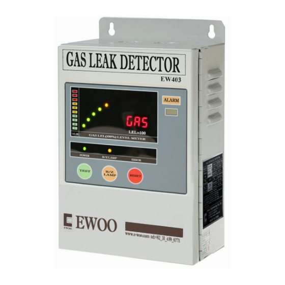
Summary of Contents for ewoo EW-403
- Page 1 GAS DETECTOR REFERANCE MANUAL MODEL: EW-403 (LNG.LPG) [ NOTICE ] ● Surely be aware of the specifications by skilled worker prior to using the product. ● Surely keep the specifications to where you are always able to see.
- Page 2 [ CONTENTS ] 1. SPECIFICATIONS 1-1. INDICATOR 1-2. SENSOR 2. PART & FUNCTION 2-1. INDICATOR 2-2. SENSOR 3. COMPOSITION 3-1. INDICATOR 3-2. SENSOR 4. OPERATIONAL SYSTEM 5. INSTALLATION 5-1. Where to install 5-2. Installation drawing 6. INSTRUCTION & CAUTIONS 7. DIMENSIONS *User’s manual is not responsible for unauthorized changes...
- Page 3 1. SPECIFICATIONS 1-1. INDICATOR Model Gas Leak Detector EW-403 Detectable Gases LPG, LNG, City Gas, Combustible Gas, Toxic Gas (NH3.H2) Power supply AC 220V. 60㎐ Power consumption Normal condition - 2.5W. Alarm condition - 3W Operating Temperature 0℃ ~ 40℃, Below 95%(RH) &Humidity...
- Page 4 2. PART & FUNCTION 2-1. INDICATOR ①Power light : Green LED is lit while Supplied by AC 220V. ②Alarm mute warning light: Buzzer Stop Yellow LED blinks if the alarm Mute button is pressed. And during this time, the audible alarm Is mute in spite of the alarm condition.
- Page 5 2-1. SENSOR ① Sticker (Explosion proof) ② Sensor cover ③ Sensor bady ④ Explosion proof approval sticker (Korea gas safety corporation approval) ⑤ Cover fixing hole: The bolt for fixing cover and body of detector (Wrench bolt M5x15) ⑥ Sensor fixing hole: The hole for fixing the detector by bolts or nails ⑦...
- Page 6 3-1. INDICATOR ○ AC FUSE (2EA): 220V 1A glass tube (When it has blown, RED warning light of the fuse gets lit) ○ Power switch: AC power supply switch ○ BUZZER: It makes audible alarm WIRING DIAGRAM - AC 220V input terminal: Please connect with rated voltage (AC 220V) - Dry contact (NO NC COM): In normal condition, COM terminal is connected with NC terminal.
- Page 7 3-2. SENSOR ○ Connector (terminal block) Blue (White) + Brown (Black)- Green (Wire of signal) Power supply of sensor + Power supply of sensor – Output of Sensor (4~20mA) (DC 24V) (DC 24V GND) ○ Zero calibration: We release the detector with it being set. Do not attempt to modify ○...
- Page 8 4. OPERATIONAL SYSTEM 5. INSTALLATION 5-1. Where to install ① The detector is designed to be installed in the area that is subject to expose to gas or the area where the leaked gas tend to stay. ② Please determine the location of the sensor considering the kind of the Gas, cautions and condition.
- Page 9 5-2. Installations drawing PLACE TO INSTALL: kitchen, Boiler room, Room of pressure regulator, Gas storage ※ 6. INSTALLATION & CAUTIONS 6-1. INSTRUCTION ①Please open the case and connect the sensor with the indicator. And connect the AC 220V power supply as well. ②Please turn on the power supply switch and wait for warm up time 1(minute) in 1minute, the detector begins to operate.
- Page 10 ⑤If you want to stop the audible alarm, please press the alarm mute Button (B/Z stop) If you do, alarm mute warning light (B/Z Stop) blinks And the audible alarm becomes mute. ⑥ When the fault light gets lit, please check the connection between Sensor and indicator.
- Page 11 7. Dimensions...


Need help?
Do you have a question about the EW-403 and is the answer not in the manual?
Questions and answers