Table of Contents
Advertisement
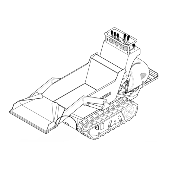
series 65 80
Minitransporter
USER'S MANUAL AND MAINTENANCE
Ed. 1
This manual should always be readily available so that the machine operator may
consult it immediately, and it must be saved for the entire duration of the machine's life.
© 2010 - The entire or partial reproduction and/or divulging of this document is prohibited in any form without the written consent of the manufacturing company. The
editing of the text, the illustrations, and the paginations were realized by "Cormidi s.r.l." The information and technical data were furnished, checked and validated by
the Cormidi Technical Office. The illustrations and technical data included in this manual are non binding: the manufacturer reserves the right to carry out
eventual modifications to its product without notice.
CORMIDI srl
Via Fonte, 342
84069 Roccadaspide (SA)
leadinginnovation
0828 943689 Fax 0828 943963
www.cormidi.com info@cormidi.com
Advertisement
Table of Contents

Subscribe to Our Youtube Channel
Related Manuals for cormidi 65 Series


Summary of Contents for cormidi 65 Series
- Page 1 © 2010 - The entire or partial reproduction and/or divulging of this document is prohibited in any form without the written consent of the manufacturing company. The editing of the text, the illustrations, and the paginations were realized by “Cormidi s.r.l.” The information and technical data were furnished, checked and validated by the Cormidi Technical Office.
-
Page 2: Introduction
CORMIDI Minitransporter. This product was designed characteristics and the information contained in the and constructed for longevity and to be used with present manual may have been varied recently. We ask maximum reliability. -
Page 3: General Information
General Information 1. GENERAL INFORMATION understand the various rights and responsibilities. 1.1. W Collaborate with your sales representative when filling out ARRANTY the form and make sure it is filled out correctly, in that the Your machine is guaranteed for 12 months from the text and the other formalities (shipment within the time date of its delivery and includes the substitution of limit, etc.) represent the legal base for the warranty on the... -
Page 4: Machine Description
Series 65-80 guarantees safety, economy of use, and a longer CAUTION: indicates potentially functional duration of the machine. dangerous situation that can provoke injury To give a higher prominence to the sections of the text or damage to the machine if the instructions which must not be ignored, they have been highlighted in are not followed. -
Page 5: Safety Information
General Information substitute missing or illegible ones. Respect all READ CAREFULLY: Determine the type of regulations contained in these. motor that has been installed in your machine accurately, and read its manual to machine made exclusively familiarize yourself with it. transportation of inert materials. - Page 6 Series 65-80 hand. PROHIBITED: It is strictly prohibited to remove protection and safety devices with Before turning on the motor, always be sure that there are not any people, animals, or things that which the machine is equipped could be an obstacle in the work area. Avoid working under unsuitable physical conditions DANGER: Never use the machine inside...
-
Page 7: Machine And Manufacturer Identification
General Information 1.5. M 1.6. S ACHINE AND ANUFACTURER DENTIFICATION AFETY EVICES The data which identifies the machine and the PROHIBITED: it is strictly prohibited to use manufacturer are listed on the aluminium plate that is the machine with its safety devices and affixed on the dashboard of the machine. -
Page 8: Blocking The Arm
Series 65-80 piston; 1.6.3. B LOCKING THE OOTREST • slowly lower the unit with the motor off until the The drive footrest must always be blocked in open correct fit of the device is obtained. position, during the work, to prevent its accidental Afterwards remove the device and put it back in its slot. -
Page 9: Accessories
General Information The machine is furnished with equippment to make it possible to carry out normal maintenance operations. It is also equipped with a hydraulic force instrument: in the manual the instructions for its use have been furnished. Also, the machine the may also be equipped upon request with particular tools including: •... -
Page 10: Safety Distance
Series 65-80 1.8.1. S AFETY ISTANCE PROHIBITED: it is strictly prohibited to remove the stickers and the safety plates Tag which alerts the which machine equipped with: serious danger of coming immediately substitute deteriorated and/or near and standing within the illegible ones. -
Page 11: Crushing
General Information 1.8.4. C functions; RUSHING • Wear a headset Tags which indicate a potential which protects risk of crushing that may cause very hearing serious injury or death. another device of this type; • Wear protective gloves fig. 9 (cod. -
Page 12: Maximum Slopes
Series 65-80 lower part shows the correct position to carry out the 1.8.10. O THER unloading safely. The label on the side (fig. 1.8.8. M AXIMUM LOPES indicates that 12-a) necessary read Completely avoid working on documentation before terrains that have latitudinal slopes intervention, to avoid technical of more than 10°... -
Page 13: Admissible Slopes
General Information 1.9. D DMISSIBLE LOPES IMENSIONS Normal Auto-loading Hi-Tip Length 1940 mm 2530 mm 2530 mm Width 800 mm 850 mm 850 mm Wheel Track 610 mm 610 mm 610 mm 1140 mm 1140 mm 1250 mm Height 1400 mm 1900 mm 2720 mm fig. -
Page 14: Technical Data
Series 65-80 1.10. T ECHNICAL Model Dumper Auto-loading Hi-Tip Type 9.65 10.80 13.80 9.65 10.80 13.80 9.65 10.80 13.80 Mass [kg] Engine petrol diesel petrol petrol diesel petrol petrol diesel petrol Power [kW] 6,7 (9,1) 7,2 (9,8) 9,3 (12,6) 6,7 (9,1) 7,2 (9,8) 9,3 (12,6) 6,7 (9,1) -
Page 15: Commands
Commands 2. COMMANDS 2.1. H YDRAULIC VERTURNING ERSION STABLE POSITION Deactivated Brake Parking Brake Command STABLE POSIZIONE The parking brake command, which also Activated Brake serves as an emergency brake, allows you to insert or deactivate the brake. fig. 15 Command lever for the parking brake STABLE POSITION Minimum regimen... - Page 16 Series 65-80 Drive Levers The command levers control the rotation of the tracks through a hydraulic feed of the hydraulic motors. The command levers are active only when the motor is turned on. UNSTABLE POSITION The left Drive Lever The left track rotates forward STABLE POSITION The left-hand drive lever controls the left track.
- Page 17 Commands UNSTABLE POSITION Command Lever for the Hydraulic Take-off Hydraulic pressure on “A” Instrument STABLE POSITION The hydraulic take-off instrument is composed Resting position of two openings with rapid transmission of standard POSIZIONE INSTABILE type, indicated by the letters “A” and “B”, situated Hydraulic pressure on “B”...
- Page 18 Series 65-80 Horn Command The horn button is on the left side of the instrument panel. To sound the horn, push the button. Only intermittent mode horn operation is enabled. Continuous mode is not enabled. The command works only with the engine running.
-
Page 19: Autoloading Version
Commands 2.2. A UTOLOADING ERSION STABLE POSITION Deactivated brake Parking Brake Command STABLE POSITION The command for the parking break, which Activated brake also serves as an emergency brake, allows one to activate or deactivate the brake. fig. 23 Command lever for the parking brake POSIZIONE STABILE Minimum regimen Accelerator Command... - Page 20 Series 65-80 Drive Levers The drive levers control the rotation of the tracks through a hydraulic feed to the hydraulic motors. The levers are active only when the motor is turned on. UNSTABLE POSITION The left track rotates forward Left Drive Lever STABLEPOSITION The left lever controls the left track.
- Page 21 Commands UNSTABLE POSITION Command Lever for the Hydraulic Take-off Hydraulic pressure on “A” Instrument STABLE POSITION The hydraulic take-off instrument is composed Resting position of two openings with rapid transmission of standard UNSTABLE POSITION type, indicated by the letters “A” and “B”, situated Hydraulic pressure on “B”...
- Page 22 Series 65-80 STABLE POSITION The bucket is free (floating) Auto-loading Command Lever UNSTABLE POSITION The command lever for the auto-loading tool Lowering of the bucket works the hydraulic levers that provoke the raising STABLE POSITION of the auto-loading bucket. Resting position This command may only be used when the UNSTABLE POSITION motor is turned on.
- Page 23 Commands STABLE POSITION Cut Off Battery Command Battery connected STABLE POSITION The device lever on the left side of the Battery unplugged dashboard controls the disconnection of the battery from the electrical circuit of the machine. STABLE POSITION Battery unplugged, it’s possible remove the lever Use the cut off battery to disconnect power from the electrical circuit, particularly if the machine stop...
-
Page 24: Autoloading Version With Swivel Bucket
Series 65-80 2.3. A UTOLOADING ERSION WITH WIVEL UCKET STABLE POSITION Deactivated brake Parking Brake Command STABLE POSITION The command for the parking break, which Activated brake also serves as an emergency brake, allows one to activate or deactivate the brake. fig. - Page 25 Commands Drive Levers The drive levers control the rotation of the tracks through a hydraulic feed to the hydraulic motors. The levers are active only when the motor is turned on. UNSTABLE POSITION The left track rotates forward Left Drive Lever STABLE POSITION The left lever controls the left track.
- Page 26 Series 65-80 UNSTABLE POSITION The bucket turns towards the Command Lever for the Swivel Bucket anterior side of the machine STABLE POSITION The swivel bucket command lever works the Resting Position hydraulic jack that provokes the rotation of the UNSTABLE POSITION bucket of the auto-loading tool.
- Page 27 Commands STABLE POSITION The bucket is free (floating) Auto-loading Command Lever UNSTABLE POSITION The command lever for the auto-loading tool Lowering of the bucket works the hydraulic jack that provokes the raising POSIZIONE STABILE of the auto-loading bucket. Resting position This command may only be used when the POSIZIONE INSTABILE motor is turned on.
- Page 28 Series 65-80 STABLE POSITION Cut Off Battery Command Battery connected STABLE POSITION The device lever on the left side of the Battery unplugged dashboard controls the disconnection of the battery from the electrical circuit of the machine. STABLE POSITION Battery unplugged, it’s possible remove the lever Use the cut off battery to disconnect power from the electrical circuit, particularly if the machine stop...
-
Page 29: Hi-Tip" Version
Commands 2.4. “H ” V ERSION STABLE POSITION Deactivated brake Parking Brake Command STABLE POSITION The command for the parking break, which Activated brake also serves as an emergency brake, allows one to activate or deactivate the brake. fig. 41 Command lever for the parking brake STABLE POSITION Minimum regimen... - Page 30 Series 65-80 Drive Levers The drive levers control the rotation of the tracks through a hydraulic feed to the hydraulic motors. The levers are active only when the motor is turned on. UNSTABLE POSITION The left track rotates forward Left Drive Lever STABLE POSITION The left lever controls the left track.
- Page 31 Commands UNSTABLE POSITION Allows the body to be raised “Hi-Tip” (High Unloading) Command Lever STABLE POSITION The command lever the “Hi-Tip” works the Resting position hydraulic jack that provokes the raising of the UNSTABLE POSITION anchoring structure of the body to consent the Provokes the lowering of the unloading in containers or tubs with a high border.
- Page 32 Series 65-80 STABLE POSITION The bucket is free (floating) Auto-loading Command lever UNSTABLE POSITION The command lever for the auto-loading tool Lowering of the bucket works the hydraulic jack that provokes the raising STABLE POSITION of the auto-loading bucket. Resting position This command may only be used when the UNSTABLE POSITION motor is turned on.
- Page 33 Commands STABLE POSITION Cut Off Battery Command Battery connected STABLE POSITION The device lever on the left side of the Battery unplugged dashboard controls the disconnection of the battery from the electrical circuit of the machine. STABLE POSITION Battery unplugged, it’s possible remove the lever Use the cut off battery to disconnect power from the electrical circuit, particularly if the machine stop...
-
Page 34: Instruction For Use
Series 65-80 3. INSTRUCTION FOR USE The machine is normally delivered completely 3.1. F IRST assembled and ready for use with an empty fuel tank. READ CAREFULLY: Before using the Fill the fuel tank, open the fuel tap and follow the start- machine you must read all of the instructions up procedure described in the appropriate paragraph. -
Page 35: Motor Start-Up
Instruction for use During the first period of use, the tracks undergo an In diesel engines, can be an automatic valve that adjustment, for which it is necessary, after the first 50 helps to raise the start, it works automatically in the hours of operation, to carry out the regulation of the first seconds of starting the engine. -
Page 36: Driving The Machine
Series 65-80 etc. that could get caught up in the tracks and WARNING: The conservation of the fuel must provoke a break. always be done with respect for the specific laws, in suitable places, away from sources of At the start-up, regulate the number of rotations of the heat, and with clean, well closed suitable engine to the desired level by activating the accelerator containers! -
Page 37: Driving Position
Instruction for use 3.5.1. D When the machine is in gear, always grasp the RIVING OSITION stronghold handle firmly with one hand and use the other During the driving of the machine and during the work, hand simultaneously to activate both drive levers. is necessary utilize the footrest platform in open position, Never release the handle to operate the command always (see fig. -
Page 38: Travelling On Slopes
Series 65-80 especially with a loaded machine, rather follow the When addressing sloped segments, especially when procedure described in the paragraph: “Travelling on the machine is loaded, you must use this particular Slopes” . driving technique (see fig. 52): Always address the uphill slopes in forward gear; DANGER: While in reverse gear, always check to see that there are no obstacles... -
Page 39: Stopping Movement
Instruction for use 3.5.7. C OUNTER ROTATION DANGER: if the machine travelling on high slope with minimum motor regimen and It is also possible to make the machine spin round, maximum opening of drive levers, “engine carrying out a complete “counter-rotation” around its axis, brake”... -
Page 40: Stopping And Parking
Series 65-80 3.6. S an emergency stop when the operator may deem TOPPING AND ARKING necessary to have an instantaneous block of the machine WARNING: If you move away from the during worko. machine and leave it unattended, always PROHIBITED: It is strictly prohibited to use activate the parking brake and be sure that no the parking brake while the machine is unauthorized persons may turn it on or move... -
Page 41: Transporting Loads
Instruction for use move it towards the left making it come out of the slot and 3.8.2. “F ” T ARMING let it go: the brake will insert itself automatically. Upon request, your machine may be fitted, in place of DANGER: In the case that you may have to the “dumper”... -
Page 42: Unloading Material
Series 65-80 “D” and take it out;; unblock the anterior side; • Loosen the two wheels “A” positioned under the • Push the lever forward to provoke the overturning of loading surface; the body and the unloading of the material; •... -
Page 43: Use Of The Self-Loading
Instruction for use • Use the lever of the auto-loading device pushing it DANGER: Never carry out the raising of the forward to place the shovel on the ground in order to body without first stabilizing the machine with stabilize the machine; the auto-loading shovel. -
Page 44: Supplementary Hydraulic Command
Series 65-80 bucket has lowered to the correct height from the To obtain pressure on the “A” opening, push the lever ground. forward. Floating (auto-levelling): the auto-loading tool To obtain pressure on the “B” opening, pull the lever may also be used to function as an auto-levelling backward, toward yourself. -
Page 45: Transport
Instruction for use electrical devices with 3.13. T RANSPORT additional features highlighted by the close WARNING: During transport, always position label (see fig. 59). the machine levelly to avoid the spilling of oil or other liquids . fig. 59 (cod. C0901.23.02) If the machine needs to be transported, one must The label on the side proceed correctly to avoid dangers to persons and/or... - Page 46 Series 65-80 length, in the following way: • Disconnect the battery, turning the device to cut off battery; • Empty the fuel tank and close the plug; • Fix the lifting hooks exclusively to the anchoring points that were prescribed by the manufacturer (fig.
-
Page 47: Towing
Instruction for use 3.14. T • Fix it to the surface of the means of transport OWING pulling down firmly, with CE compliant ropes, and The machine is equipped with tow always connecting to the points as indicated in the hooks, located at the bottom of the figure 64. -
Page 48: Storage
Series 65-80 3.15. S out and conserve in a safe place. TORAGE When putting the machine back into service: Whenever the machine must remain inactive for • carry out all greasing again in all prescribed points several months, it is necessary to provide a correct found in the specific chapter;... -
Page 49: Maintenance
Maintenance 4. MAINTENANCE Maintenance and Adjustment Table DANGER: always carry out all maintenance operations with the motor off and with the Work start up keys not inserted. Description Frequency A good maintenance is necessary and is the secret to obtaining low running costs, to lengthening the life of your Machine machine, and to always maintaining it at its highest Drive Levers... -
Page 50: Motor
Series 65-80 4.2. M 4.2.1. P OTOR FILTER AND ILTER IN AN OIL BATH Your machine can be equipped with a special air filter in READ CAREFULLY: Carefully read the an oil bath, which increases and improves the filtration instructions and the mode of use for the capacity. - Page 51 Maintenance Every 15 days, to check the oil level in the filter, cartridge “C” and change the oil in the filter bowl cup. release the bottom cup of the filter (fig. 68), loosening To clean the cartridge is recommended to wash by the hooks “G”.
-
Page 52: Hydraulic Circuit
Series 65-80 reading the value on thermometer “B” (see fig. 69): the 4.3. H YDRAULIC IRCUIT temperature is considered regular when it does not 4.3.1. H surpass 85° C. YDRAULIC Verifying Oil Level REQUIRED: Avoid the dispersion of oil in the environment and carry out the disposal with Check the level of hydraulic oil in the Every 8 hrs... - Page 53 Maintenance adding the oil specified into the opening “A”; Substitution • Screw the top “A” back on sealing it properly, and turn Substitute the hydraulic oil in the Every 300 hrs on the motor following the correct procedure; tank. • Briefly operate the drive levers and the command levers;...
-
Page 54: Hydraulic Oil Filter
Series 65-80 frame, under the body. One of the filters, which is an aspirator. immersion type, is screwed directly into the tank (see fig. DANGER: Always carry out the emptying 70 pos “G”), while the other one which is a cartridge type operation of the lower tank when the motor is (see fig. -
Page 55: Tracks
Maintenance 4.4. T • Lightly lubricate the washer of the new filter; RACKS • Screw the new filter down well, clenching tightly by Registration hand only; • Refill the oil level again. Every 50 hrs Register the tension of the tracks. Services Circuit The correct ten- Substitute... -
Page 56: Parking Brake
Series 65-80 Substitution wheel “G”; • Register the tension by working on nut “D”; DANGER: Never work with the machine • Check that the arrow is at 30mm; raised on a jack or suspended, rather always • When the registering is done, block the counter-nut place it upon suitable trestles that can “C”;... -
Page 57: Greasing
Maintenance tion of the cursor “E”; using a suitable grease. • Tighten the nut “B”; Grease the drive levers using a spray type lubricant. 4.6. G REASING Hub Wheel Refurnish grease Every 8 hrs prescribed points. Every 200 hrs Greasing the hubs of the wheels. Periodically also necessary... -
Page 58: Recommended Lubricants
Series 65-80 4.7. R ECOMMENDED UBRICANTS Type Quantity Motor Oil 15W40 Hydraulic Oil AT FII 16 l Grease thick fluid... -
Page 59: Inconveniences And Breakdowns
Inconveniences and breakdowns 5. INCONVENIENCES AND BREAKDOWNS Inconvenience Causes Remedy Excessive oil level. Correct the oil level Overheated oil. Turn off the machine and let it cool down Hydraulic oil is leaking. Have the machine looked at by a mechanic with Breakdown in the hydraulic circuits. - Page 60 Series 65-80 Inconvenience Causes Remedy The parking brake is activated. Deactivate the parking brake Not enough oil in the hydraulic circuit. Restore oil to the correct level The machine does not move. The tracks are broken. Replace the tracks Breakdown in the hydraulic Have the motor looked at by a mechanic with this components.
-
Page 61: Index
Index 6. INDEX Accelerator of Parking, Registering Drive Command Lever of Parking, Mainutenance Levers of - 14; 18; 23; 28 Command Lever- of Parking, Using Driving Command Lever- breakdown, Inconveniences and - the Machine Command Lever- Breaking-in Period Driving Registration See Attached Cleaning Air Filter See Attached... - Page 62 Series 65-80 Circuit -, Maintenance Parking Brake Command Verifica Livello Supplementary - Command Leverof Accelerator Command Other Tags Hydraulic Oil Lift Overturning of the Body Restoring Level Blocking the Parking Substitution Livello Brake of - Verifying Level Olio Idraulico Brake of -, Maintenance Verifying Temperature Machine Stopping and -...
- Page 63 Travelling Hot Surface on Slopes Maximum Slopes Unloading Material Overturning Safety Distance Instruction for - Safety Tags of the Auto-loading Caution Using Self-loading Emergency Brake Slopes of Parking Brake Travelling on - Verifica Sostituzione Livello Olio Idraulico Olio Idraulico Verify Stopping Hydraulic Oil Level and Parking...
-
Page 64: Table Of Contents
Series 65-80 7. SUMMARY Introduction ..............2 Admissible Slopes ..........11 1. General Information ..........1 1.9. Dimensions ........... 11 1.1. Warranty ............1 1.10. Technical Data ..........12 1.2. Goal of the Manual.......... 1 2. Commands ............13 1.3. Machine Description ........2 2.1. - Page 65 Summary 3.8.1. Construction Body (Dumper) ....39 3.8.2. “Farming” Type Body ......39 3.9. Unloading Material ........40 3.9.1. Overturning of the Body ......40 3.9.2. Raising the Body (“Hi-Tip”) ....40 3.10. Use of the Self-loading ......... 41 3.11. Supplementary Hydraulic Command .... 42 3.12.
- Page 66 Series 65-80...
Need help?
Do you have a question about the 65 Series and is the answer not in the manual?
Questions and answers