
Related Manuals for cahors CAP5510


Summary of Contents for cahors CAP5510
- Page 1 INSTRUCTIONS Digital Terrestrial Programmable Amplifiers CAP5510 REF. 0145056R13 CS 60022 • 46003 Cahors cedex 9 - France Tél. +33 (0)5 65 35 82 20 • Fax +33 (0)5 65 35 82 52 www.cahors-ced.com www.groupe-cahors.com SUMMARY...
-
Page 2: Installation
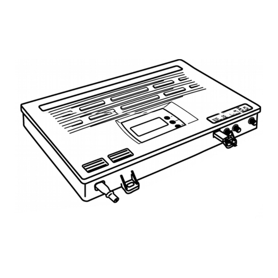
DESCRIPTION 1 / Presentation 2 / Programming INSTALLATION 1 / Wall assembly 2 / Connecting the antennas PROGRAMMING 1 / Power 2 / LTE filter programming 3 / Configuration 4 / Programming of the filters 5 / Deactivation of unused filters 6 / UHF input attenuator setting 7 / Setting of the cross fader floor 8/ B.I + FM, B.III/DAB and AUX input setting... - Page 3 1 / Presentation: The CAP5510 is a programmable amplification for analog and digital channels central land. The control unit can be programmed to select the frequency range of UHF 21-69 input / 21-60 (Lte 4 G) / 21-48 (Lte 5 G) and it allows to amplify 10 filters UHF with a capacity of 1 to 7 channels each.
- Page 4 a) By means of a built-in Scheduler consists of a keyboard and a display which is located on the central part. b) by using a graphics software for PC Windows compatible (connecting through the USB from the central door). c) By a tablet with operating system Android 4.0 or successive. The application is optimized for tablet with screen from 5 "to 10".
- Page 5 INSTALLATION 1 / Wall mount: The central CAP5510 housing must only be installed indoors or in a protective Cabinet. The external dimensions of the CAP5510 are: 320 (width) x 260 (height) x 40 (depth) mm It must be installed in a place protected and sufficiently ventilated to avoid any risk of overheating (do not cover the different ventilation openings).
- Page 6 At power-up, the letter b is displayed to indicate the phase of boot by the microprocessor. Then, the reference of the firmware will be displayed to confirm the correct function of the system implementation. During power-up, the version of the software from Central appears a few seconds. Once the complete boot sequence, the display turns off.
- Page 7 Group filters attributes: 7 filters to the UHF1 input and 3 filters in the UHF2 input Each filter can be set to a width of variable bandwidth between 8 and 56 Mhz in 8 Mhz increments, 1 channel UHF 7-channel UHF channel increments. So the configuration can manage : 1 to 49 UHF channels by the entered UHF1...
- Page 8 L 100 Press the button ⋀, is displayed. This function allows you to set the 1 – 0 to 30 dB filter attenuation in 1 dB increments. Repeat the same procedure for setting the filter n ° 2. If you want to filter affects only a single channel (ex: C21), adjust the 1 F1.21 channel of the selected filter on...
- Page 9 LU00 Press 'OK', the display will start flashing. With touch ⋀ and ⋁ adjust the general attenuation UHF level. Press the 'OK' button again to confirm. 8. Setting B.I/FM, B.III/DAB B.I + FM, B.III/DAB entries are equipped with attenuators from 0 level to-30dB. With touch ⋀...
- Page 10 UHF and VHF of the amplifier, press ⋀ and ⋁. The display shows in sequence the UHF1-UHF2, BI, B3 entries The word ' oF ' means that the entry does not remote supply. The word ' on ' means that there is a tension. To change the status of the inputs, press the 'OK' button.
- Page 11 Note: P.000 means that the protection (of default) code has been disabled. 12 / RESET of the Central At any time, the factory amplifier can be restored (all filters without programmed channels and all filters and attenuator set to 0 dB). Disconnect the power from the power supply.
-
Page 12: Antenna Connection
3 / LIQUIDS This plant must be protected from splashes. Make sure that no container containing liquid is placed on or above the Central and that no other person do not spill liquid or splashes Central. 4 / CLEANING Unplug the power before cleaning. Use only a damp cloth (no solvents). 5 / VENTILATION To ensure adequate air circulation and avoid overheating, the vents on the hood must not be obstructed. - Page 13 not be obstructed. The station must not be installed in an airtight area. Do not install the unit on unstable signs, tripods or table where it could fall. A central drop can cause physical injury and material damage. 11 / VOLTAGE PEAKS In case the plant would be subject to accidental voltage peaks, it is advisable to disconnect the Central sector and the antennas.
Need help?
Do you have a question about the CAP5510 and is the answer not in the manual?
Questions and answers