Table of Contents
Advertisement
Quick Links
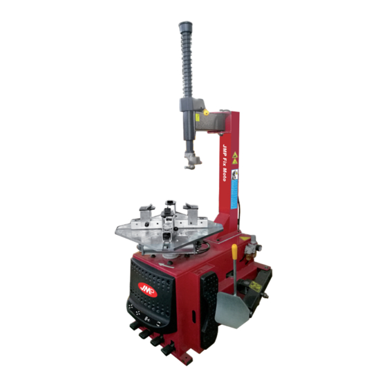
Tyre Changer JMP Fix Moto
(Translation of original operating instructions)
Revision 2: As of serial number 2018-01-2061
Reifenmontiermaschine JMP Fix Moto
D
Montermaskine JMP Fix Moto
DK
Zmieniarki do opon JMP Fix Moto
PL
Desmontadora neumáticos JMP Fix Moto
E
Smontagomme JMP Fix Moto
I
Johannes J. Matthies GmbH & Co. KG
Hammerbrookstr. 97
20097 Hamburg, Deutschland
www.jmproducts.eu
info@jmproducts.eu
JM-No. 677 03 08
1
Advertisement
Table of Contents

Summary of Contents for JMP Fix Moto
- Page 1 (Translation of original operating instructions) Revision 2: As of serial number 2018-01-2061 Reifenmontiermaschine JMP Fix Moto Montermaskine JMP Fix Moto Zmieniarki do opon JMP Fix Moto Desmontadora neumáticos JMP Fix Moto Smontagomme JMP Fix Moto Johannes J. Matthies GmbH & Co. KG Hammerbrookstr.
-
Page 2: Table Of Contents
Contents: 1. Introduction............................1 2. Warning labels and danger spots .....................1-2 3. Technical data ............................. 2 4. Transportation ............................. 2 5. Unpack & checking for completeness and damage ................2 6. Workplace requirements ........................2 7. Position and installation........................3 8. -
Page 3: Introduction
Operating and Maintenance Manual Warning This operating manual is very important for operation of the machine. Please read it carefully before you install and use the ma- chine. This manual also serves to ensure safe use and maintenance of the machine. Please keep this manual so that you will also have it on hand later for maintenance of the machine.. -
Page 4: Technical Data
Safety warning signs Caution: If the safety warning signs are folded down or have become detached, please replace them immediately with new ones! Do not operate the machine if safety warning signs are missing or insufficiently visible. Always ensure that the safety warning signs are clearly visible at all times and not covered by objects. 3. -
Page 5: Position And Installation
7. Position and installation Remove the ground screws, set up the machine and align it with a spirit level. Then secure the machine with all the screws and ensure that it is standing stably on the ground. Ensure that the machine also has an adequate earthing circuit to pre- vent short circuiting. -
Page 6: Levering The Tyre Bead
9.1. Levering the tyre bead Ensure that the tyre is completely deflated and position the tyre against the stop buffer (S). Now hold the bead breaker blade (R) approx. 10 mm away from the edge against the bead as shown in Fig. 5. Press the levering pedal (U) to lever off the tyre. Repeat this procedure at different positions around the tyre and on both sides until the tyre bead has been completely loosened. -
Page 7: 0. Inflating The Tyre
10. Inflating the tyre Important: There is an increased risk of injury during the inflating process! Please be especially careful and follow the instructions precisely. It can be very dangerous during inflating if problems are encountered with the tyre or rim. If the tyre bursts or is destroyed due to inadequate pressure or overpressure, the tyre parts are flung out in all directions by the pressure and, due to the enormous force which develops, there is definite risk to the life and limb of persons in the vicinity. Tyres may burst due to the following circumstances: The wheel rim and tyre are not the same size. The tyre or wheel rim is damaged. The tyre has been inflated beyond the maximum tyre pressure recommended by the manufacturer. The operator has not observed the safety instructions. Proceed as follows in this case: Remove the valve cap from the valve. - Page 8 Note: Fig. 10 Press the drain valve to allow the water in the water container to drain. Note: After 20 days of operation, tighten the clamping jaws on the turntable (Fig. 10) with fastening screws (B). Note: If the turntable does not work with full force, please check that the belt is tightly fitted and observe the following steps: Remove the right-hand housing by unscrewing the screws. Tighten the two screws under the motor support firmly, maintaining a sufficient distance between the motor support and motor block. Tighten the screws to tension the strap adequately (Fig. 11).
-
Page 9: Troubleshooting Table
13. Troubleshooting table Problem Cause Solution Turntable only rotates in one direction or Reversing switch does not work Replace reversing switch does not turn at all (page 11, part 200-426) Belt defective Replace belt Motor is malfunctioning Check motor cable or connection on motor terminal box. - Page 10 600-101 CX-204-250000-0 Square column 200-102 CX-200-190000-0 Pivot arm pin B-014-140301-0 Hex. screw M14x30 B-050-140000-0 Spring washer Ø14 CX-200-140000-0 Large washer 200-106D C-206-350000-D Column adjusting handle B-010-100501-0 Hex. socket screw M10x50 200-120D C-206-490000-D Valve arm cover 200-D 200-121 C-200-390000-0 Valve arm spring B-040-102020-1 Flat washer Ø...
- Page 11 221-201 CX-221-130000-0 Turntable 630 206-204 C-206-570000-0 Clamping jaw 206 CX-200-140000-0 Large washer B-050-160000-0 Spring washer Ø16 B-014-160401-0 Hex. screw M16x40 C-200-440000-0 Cover turntable 200-209 CX-200-310000-0 Structure connecting rod 200-210 CX-200-280000-0 Square turntable 540 CX-200-290000-0 Washer square turntable B-055-650001-0 Locking ring Ø65 (shaft) 206-214 CX-206-110100-0 Jaw slide with contact 200-221 B-040-122520-1...
- Page 12 200-301 B-010-140301-0 Hex. socket screw M14x30 B-040-162820-1 Flat washer B-001-060001-0 Self-locking nut M6 702-D C-206-070200-D Cover handle bead breaker blade S-018-010408-0 Screw connection 200-322 CX-200-030000-0 Tyre lever arm 200 (90°)1/4-Ø8 B-004-160001-1 Nut M16*1.5 200-323 CX-200-040000-0 Tyre lever connector B-040-162820-1 Flat washer Ø 16*28*2 200-324 CX-200-050600-0 Tyre lever cylinder turning...
- Page 14 B-010-060201-0 Hex. socket screw M6x20 CW-110-020000-0 5-way valve (L-screw connec- tion, without rod) 200-414 C-200-380000-0 Pedal spring CW-110-020001-0 5-way valve (T-screw connec- tion, without rod) 206D-2 CX-206-110000-D Connecting rod for tyre lever 200-449 C-200-060901-0 5-way valve tube cylinder 206D-3 CX-206-070000-D Pedal support for tyre lever 200-451 C-200-061100-0 5-way valve cover...
- Page 15 200-501 C-300-320302-0 Cover gears bottom S-040-030204-0 Bearing 30204 S-005-020080-1 Gearbox gasket ȹ20*35*8 200-504 C-200-320500-0 Gear tensioner B-014-080251-0 Hex. screw, outer M8*25 B-065-006020-0 Cotter pin washer 6x20 200-507 C-200-320400-0 Worm rod S-040-006010-0 Bearing 6010 200-509 C-200-320200-0 Worm shaft 200-510 C-200-320100-0 Worm gearbox 200-511 CZ-200-320600-0 Spacer B-014-100551-0...
- Page 16 200-504 C-200-320500-0 Gear tensioner U200 601-MY S-050-230075-0W Motor, tyre changer 220V- 240V/50Hz 200-602 CX-200-330000-0 Tensioner motor U200 B-007-080121-0 Hex. tensioning screw M8x12 604D S-042-000620-0 Belt, tyre changer B-014-080651-0 Hex. screw, outer M8x65 B-040-083030-1 Flat washer Ø8*30*3 607-80 S-063-008000-0 Capacitor 80UF,110V 607-50 S-063-005000-0 Capacitor 50uf 220V...
-
Page 17: Electrical Circuit Diagram
15. Electrical circuit diagram 16. Pneumatic circuit diagram...
Need help?
Do you have a question about the Fix Moto and is the answer not in the manual?
Questions and answers